Automatic modelling of rubble mound breakwaters from LiDAR data
M. Bueno a, L. Díaz-Vilariño a, H. González-Jorge a,*, J. Martínez-Sánchez a, P. Arias aa Applied Geotechnologies Group, Dept. Natural Resources and Environmental Engineering, University of Vigo, Campus Lagoas-Marcosende, CP 36310 Vigo, Spain (mbueno, lucia, higiniog, joaquin.martinez, parias)@uvigo.es
Commission I, WG VI/4
KEY WORDS: breakwaters, water defences, LiDAR, point cloud, 3D modelling.
ABSTRACT:
Rubble mound breakwaters maintenance is critical to the protection of beaches and ports. LiDAR systems provide accurate point clouds from the emerged part of the structure that can be modelled to make it more useful and easy to handle. This work introduces a methodology for the automatic modelling of breakwaters with armour units of cube shape. The algorithm is divided in three main steps: normal vector computation, plane segmentation, and cube reconstruction. Plane segmentation uses the normal orientation of the points and the edge length of the cube. Cube reconstruction uses the intersection of three perpendicular planes and the edge length. Three point clouds cropped from the main point cloud of the structure are used for the tests. The number of cubes detected is around 56 % for two of the point clouds and 32 % for the third one over the total physical cubes. Accuracy assessment is done by comparison with manually drawn cubes calculating the differences between the vertexes. It ranges between 6.4 cm and 15 cm. Computing time ranges between 578.5 s and 8018.2 s. The computing time increases with the number of cubes and the requirements of collision detection.
* Corresponding author.
1. INTRODUCTION
Beaches, ports, piers, and marinas must be protected from ocean waves and storms. Rubble mound breakwaters are one of the typical structures used for this purpose (Corredor et al. 2013; Altomare et al. 2014). Breakwaters are usually constructed by armour units, such as cubes, cubipods, tetrapods, dolos, etc. The energy of the ocean induces movements on the armour units that degrade the structure. One of the common techniques to monitor the movements of the armour units is the LiDAR survey that provides dense and accurate point clouds from the emerged part of the structure (Puente et al. 2014). LiDAR can be combined with hydrographic techniques such as multibeam echo sounders allowing the acquisition of the underwater geometry and, thus, completing the 3D point cloud from the structure.
LiDAR point clouds are massive amount of unorganized data that is difficult to handle. Thus, the generation of simplified CAD models based on the parameterization of the surfaces is a commonly proposed strategy (Remondino 2003; Lindenbergh 2005). In the case of cube armoured rubble mound breakwaters, the 3D reconstruction of a simplified model is achieved from the vertexes of the unit. Several types of algorithms are proposed in the literature for surface reconstruction and shape modelling. Some techniques look for sets of points in the scene that fit planes and primitives for surface identification in cluttered scenes while other involve edge detection approaches to define the bounds of given geometric shapes. Region growing techniques segment points in different geometric shapes or surfaces based on common features in neighbouring areas (Huang et al. 2001). Normal vectors are popular feature descriptors used for point cloud segmentation, especially for planar surfaces (Yoon et al. 2007; Rusu 2010).
The aim of this work is to present an algorithm for the extraction of an eight-vertex model from each armour unit. A data-driven method is used, although a model based procedure could also be applied. It uses the neighbourhood region
information to obtain the normal vectors, which are the basis for point segmentation. Segmentation results are subsequently grouped in perpendicular planes. The main idea is to use the geometric characteristics of the cube primitive to reconstruct the armour units of the structure. The proposed algorithm operates semi-automatically and requires some user-defined parameters: the number of neighbours (K) needed for computation of normal vectors, the radius distance search (D) for the segmentation, and the length of the armour units (L).
The manuscript is organized as follows: materials and methods (section 2), algorithm explanation (section 3), performance and error measurements (section 4), and conclusions (section 5).
2. MATERIALS AND METHODS 2.1 Study area
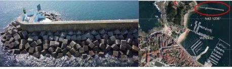
A rubble mound breakwater located in Baiona (Northwest of Spain) was used for testing the developed algorithm (Figure 1). The breakwater is made of a single layer of cubes of 1.25 m length each. It shows a length of 340 m, a crest width of 8.4 m, a crest height of 8.5 m, structure base width of 21.7 m, and slope of 49º (González-Jorge et al. 2014).
Figure 1. Baiona breakwaters image (left) and orthoimage with the port highlighted in red (right).
2.2 Data acquisition
Data acquisition was performed using a terrestrial LiDAR Faro Focus 3D and five scan positions to provide a complete point The International Archives of the Photogrammetry, Remote Sensing and Spatial Information Sciences, Volume XL-3/W3, 2015
cloud from the structure. Scan positions were selected on the breakwaters shoulder at a distance of approximately 10 m. LiDAR was tilted to improve the visibility. The point cloud resulting after registration shows around 13 million points. Manual point picking was used for coarse registration and ICP for fine registration. The point cloud was used in a raw format, without applying any method as those based on voxel techniques. Figure 2 shows a point cloud crop from the breakwaters.
Figure 2. Point cloud crop from the breakwaters.
3. ALGORITHM DESCRIPTION
The algorithm uses the point cloud previously scanned and registered as input data. The algorithm consists of three main steps: normal vector computation, plane segmentation, and cube reconstruction.
3.1 Normal vector computation
Normal computation is done based on principal component analysis (PCA) of the K nearest neighbours (KNN) of a target point pi used (Liang et al. 2013). The process starts by
searching the K-nearest neighbour (KNN; K is an input parameter to the algorithm defined by the user; 50 in this case). Once all the KNNs are found, the normal vectors for each point
pi in the point cloud are computed. The value of each
coordinate from the KNN is extracted, preparing the data for the PCA evaluation. The covariance matrix of the points is computed and the eigenvectors and eigenvalues calculated. The normal vector is the eigenvector that corresponds to the smallest one eigenvalue.
Next step is the point classification based on the normal vectors. The variance of the normal vectors is small on a planar region (cube faces) and large on the edges and corners of the cubes. The points with smaller variance act as seeds in further steps.
3.2 Plane segmentation
Once the normal vectors are computed it is possible to initiate the reconstruction process. The algorithm starts on a seed (small variance) and searches for points that lie inside a radius D and
the normal vectors present a difference lower than a threshold T
(region growing approach). These parameters are introduced by the user. In this case D = 0.5·L (L = 1.25 m) and T = 0.1 (10 %
difference between the normalized normal vectors). Once the points that fulfil the segmentation criteria are found a representative plane is computed by least square fitting. The
plane is parameterized by a centroid and a normal vector. It is necessary to work only with the planes that have enough amount of points to perform an accurate enough least square fitting.
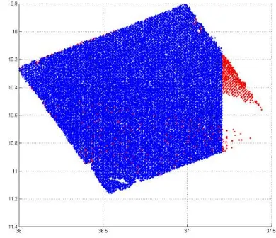
If the seed point is not around the centre of the face of the cube, the segmented plane is probably incomplete, since the searching radius D is not covering all the face length of 1.25 m (Figure 3
and 4). Thus, the segmentation process will segment two or more incomplete planes. Due to this reason, a grouping of the contiguous segmented planes is performed. This is done by searching for the planes that show a distance between the two centroids smaller than D and parallelism between the normal
vectors of the planes.
Figure 3. Plane grouping example. Points in blue and in red are grouped in the same plane after first segmentation.
Figure 4. Plane segmentation of the whole point cloud. Red points are segmented points to calculate planes. Blue points are the remainder points not used for plane fitting.
3.3 Cube reconstruction
The cube reconstruction starts from the segmented planes, their centroids, and normal vectors. The distances between the centroids of the planes and the angles between their normal vectors are used. Cube reconstruction uses three perpendicular planes.
The process starts searching for three perpendicular planes, with the centroids located within at a predefined distance. Once the three planes are detected, their intersection is computed. This computation allows the evaluation of the first vertex of first cube. It is important to notice that complete planes are not required for the process. Even if the LiDAR is able to scan only The International Archives of the Photogrammetry, Remote Sensing and Spatial Information Sciences, Volume XL-3/W3, 2015
a small part of the cube, the intersection of the three planes ensures that the vertex is reconstructed. Once this vertex, P1, is
calculated, the reconstruction of the other vertexes is a geometric problem. The main drawback is that the actual direction of the normal vector is unknown, so first the algorithm needs to check on which side of the plane the vertex is physically placed. This can be done calculating the distance between the points on one of the planes and the two possible vertexes. The first step is to calculate the two possible vertexes with the normal vectors and the distance L (P21 and P22). In the
left of Figure 5 this situation is presented. The magenta star is
P1, the intersection between the planes. The green arrow and
the black arrow are the normal vectors that will force the direction of the tentative second vertex. The two possible vertexes are the two small triangles. If the distance between the centroids of red or blue planes and the triangles is computed, the lowest value indicates the correct vertex (the cyan triangle in this example). The process is repeated with the rest of the vertexes until all of them are obtained.
Once the eight vertexes for each cube are calculated, the cube proper location is checked to avoid cubes collision. If no collision is detected, the candidate cube formed by eight vertexes is plotted, saved, and the used planes marked to avoid reuse (Figure 5: right).
Figure 5. Vertexes reconstruction from the segmented planes (left). Cube reconstruction (right); P1 is the magenta star and P2 the yellow triangle.
3.4 Collision detection
Incorrect reconstruction of cubes can produce collision of units (overlapping), which is physically impossible. Therefore, once the algorithm obtains a cube as candidate, it should be checked if there are no other cubes available for the same position. This cube cannot be plotted and saved until this condition is tested. The collision detection is assessed in two steps: first of all, the distances between the centroids of the cubes are computed. If such distance is larger than L, the cube is then placed and saved.
The second step only takes place if the first one fails. If the distance between the cube candidate and at least one of the cubes already stored is smaller than L then the overlapping is
quantified. A small amount of overlapping does not mean that the cube is in a bad position or is a ghost cube. In this case the threshold is defined on 50 intersected points.
4. RESULTS AND DISCUSSION
One of the main interests of modelling rubble mound breakwaters is the evaluation of movements in the units composing the structure. Therefore, the algorithm accuracy needs to be ensured. The accuracy assessment was performed
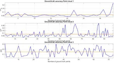
comparing the automatic reconstruction of a number of vertexes with those obtained from manually reconstructed drawing lines and vertexes over the point cloud using 3D CAD software. The accuracy is evaluated computing the distance from each vertex point in the ground truth to the vertexes computed by the proposed algorithm. Then, the results for all vertexes under study are averaged to obtain a single representative value of accuracy (Figure 6). The authors have chosen an approach based on vertexes, not based on planes, because they are easy to be manually marked.
It is important to notice that the proposed algorithm reconstructs a perfect vertex, while the ground truth is not a perfect one. As can be seen in the pictures taken from the breakwaters, the cubes present rounded vertexes and edges. Three point clouds cropped form the structure are used for the evaluation, presenting accuracies of 7 cm, 8.6 cm, and 15 cm respectively. This methodology has been used instead of using the complete point cloud to make it more manageable from a computational point of view.
Figure 7 shows the model comparison between the original point clouds and the reconstructed models. The original point clouds are showed with the normal vectors to facilitate the face detection of the cubes. As can be seen in Figure 7, the reconstruction of point cloud 1 represents a high quality in terms of number of cubes reconstructed and accuracy. Point clouds 2 and 3 show poorer results. The main reason for the missed cubes in these point clouds is that the planes detected do not fulfil all the conditions described in 3.3 to reconstruct the cubes.
Figure 6. Accuracy for three point clouds under study. In blue the accuracy for each vertex and in orange the average accuracy value.
Figure 7. Point clouds model comparison. (a) Original point cloud 1, (b) point cloud 1 reconstructed model, (c) original point cloud 2, (d) point cloud 2 reconstructed model, (e) original point cloud 3, and (f) point cloud 3 reconstructed model.
The proposed algorithm needs to be also analysed in terms of the time elapsed in the different steps and the number of cubes detected. The algorithm was implemented in MatLAB on a Quad Core CPU @ 2.44 GHz with 4 GB RAM.
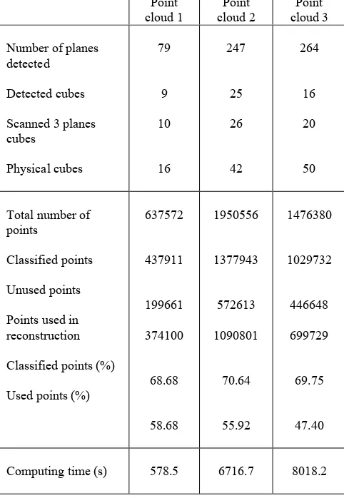
Table 1 represents the different performance of analysed parameters. The number of cubes detected against the number of cubes on ground truth is around 90 % and 96 % for point clouds 1 and 2 respectively, where the point density is higher and the scanned data seems to be more complete. Point cloud 3 shows a result around 80 % on the 3 planes ground truth. The total relationship between the detected cubes and the ground truth data is around 56 % for point clouds 1 and 2, and 32 % for point cloud 3. In any case, the number of cubes is consistent and the main target of the algorithm could be achieved. On the analysis of the points used and classified the three point clouds present similar results. There is a mean of 50 % of points that were useful to the reconstruction of the 3D model. The computation time increases when the number of cubes increases, due to the collision detection, which at this stage takes a big amount of time to work since it checks the collision against all the cubes for each candidate. If the time elapsed per cube reconstruction is evaluated, in the worst case is around 7 minutes.
Table 1. Performance of analysed parameters.
CONCLUSIONS
An algorithm for reconstructing the armour cubes from rubble mound breakwaters using LiDAR data is presented. A key
property of the algorithm is the minimal user interaction needed. It works with a few input parameters and is able to extract accurately well-defined cube primitives. The algorithm is divided in three main steps: normal vector computation, plane segmentation, and cube reconstruction.
Normal vector computation is done using PCA analysis of the k-nearest neighbours.
Plane segmentation starts with a seed point located in a region with small variance and searches for the points inside predefined radium with normal vector differences lower than a predefined factor.
Cube reconstruction is based on the intersection of three planes to obtain the first vertex. Planes can be complete or not. The other seven vertexes of the cube are defined using the length of the armour cube. It takes into account the distances between the vertexes and the centroids of the segmented planes.
Accuracy assessment was performed by comparison with manually drawn cubes of three point clouds cropped from the original one. Differences range between 7 cm and 15 cm. The number of detected cubes is around 56 % in point clouds 1 and 2 and 32 % in point cloud 3. A monitoring of more than 50 % of the cubes of the breakwaters seems to be a powerful tool to improve maintenance operations in rubble mound breakwaters.
Computing time is evaluated resulting in 578.5 s for point cloud 1, 6716.7 s for point cloud 2, and 8018.2 s for point cloud 3. It typically increases with the number of detected cubes: 9 cubes in point cloud 1, 25 cubes in point cloud 2, and 16 cubes in point cloud 3. However, the number of points is not the only parameter and other aspects as those related with the number of cubes that collide must be taken into account.
The curved area of point cloud 3 does not show good performance in cube reconstruction. This fact probably comes from the cubes that are aligned with each other.
ACKNOWLEDGEMENTS
Authors want to give thanks to the Xunta de Galicia (CN2012/269; R2014/032) and Spanish Government (Grant No: TIN2013-46801-C4-4-R; ENE2013-48015-C3-1-R; FPU: AP2010-2969).
REFERENCES
Altomare, C., Crespo, A., Rogers, B., Domínguez, J., Gironella, X., and Gómez-Gesteira, M. 2014. Numerical modelling of armour block sea breakwaters with smoothed particle hydrodynamics. Computers and Structures 130, 34 – 45.
Corredor, A., Santos, M., Peña, E., Maciñeira, E., Gómez-Martín, E., Medina, J. R. 2013. Designing and constructing cubipod armored breakwaterse in the ports of Malaga and Punta Langosteira (Spain). Proceedings of Coasts, Marine Structures,
and Breakwaters 18 – 20.
González-Jorge, H., Puente, I., Roca, D., Martínez-Sánchez, J., Conde, B., Arias, P. 2014. UAV photogrammetry application to the monitoring of rubble mound breakwaters. Journal of
Performance of Constructed Facilities.
Huang, J. and Menq, C. H. 2001. Automatic data segmentation for geometric feature extraction from unorganized 3D coordinate points. IEEE Transactions on Robotics and
Automation 17(3): 268 – 279.
Liang, J., Park, F., and Zhao, H. 2013. Robust and efficient implicit surface reconstruction for point clouds based on convexified image segmentation. Journal of Scientific
Computing 54(2-3), 577 – 602.
Lindenbergh, R., Pfeifer, N., Rabbani, T. 2005. Accuracy analysis of the Leica HDS3000 and feasibility of tunnel deformation monitoring. Proceedings of the ISPRS Workshop of
Laser Scanning 36, 1 - 6.
Puente, I., Sande, J., González-Jorge, H., Peña-González, E., Maciñeira, E., Martínez-Sánchez, J., Arias, P. 2014. Novel image analysis approach to the terrestrial LiDAR monitoring of damage in rubble mound breakwaters. Ocean Engineering 91,
273 – 280.
Remondino, F. 2003. From point cloud to surface: The modeling and visualization problem. International Archives of Photogrammetry, Remote Sensing, and Spatial Information
Sciences 34(5), W10.
Rusu, R. B. 2010. Semantic 3D object maps for everyday manipulation in human living environments. KI-Künstliche
Intelligenz 24(4), 345 – 348.
Yoon, M., Lee, Y., Lee, S., Ivrissimtzis, I., Seides, H. P. 2007. Surface and normal ensembles for surface reconstruction.
Computer Aided Design 39(5), 408 – 420.