TOWARDS IMAGE DOCUMENTION OF GRAVE COVERINGS AND EPITAPHS FOR
EXHIBITION PURPOSES
Guenter Pomaska a, Nikolay Dementiev b
a
University of Applied Sciences Bielefeld, Department of Architecture and Civil Engineering, Bielefeld, Germany [email protected]
b
Vologda State University Russia, Faculty for Civil Engineering [email protected]
CIPA 25th International Symposium Taipei, Taiwan
KEY WORDS: Structure from Motion, Mesh Processing, Rendering, Raspberry Pi, Python, Image Presentation
ABSTRACT:
Epitaphs and memorials as immovable items in sacred spaces provide with their inscriptions valuable documents of history. Today not only photography or photos are suitable as presentation material for cultural assets in museums. Computer vision and photogrammetry provide methods for recording, 3D modelling, rendering under artificial light conditions as well as further options for analysis and investigation of artistry. For exhibition purposes epitaphs have been recorded by the structure from motion method. A comparison of different kinds of SFM software distributions could be worked out. The suitability of open source software in the mesh processing chain from modelling up to displaying on computer monitors should be answered. Raspberry Pi, a computer in SoC technology works as a media server under Linux applying Python scripts. Will the little computer meet the requirements for a museum and is the handling comfortable enough for staff and visitors? This contribution reports about the case study.
1. INTRODUCTION
1.1 Historical Background: Reformation in Europe Pastor Jon Wyclif, who acted in England in the 14th century, and Jan Hus, university professor at Prague, executed 1415 as a heretic in Konstanz, be classified as the predecessors of the clerical renewal movement in Europe. Even though the beginning of the Protestant Reformation is dated to 1517, where in Wittenberg Martin Luther stroke his thesis to the Castle Church. The period of Reformation was again and again accompanied by war. It was Thomas Müntzer who felt victim to the Peasant War. The counter-reform led to the Thirty Years War ending in 1648 with the Peace of Westphalia. This incident caused the disunion of Christianity in Catholic, Lutheran and Reformed Confessions.
Calvinism is a Reformed Protestantism school, based on the teachings of the French Reformer Johannes Calvin. His thinking had great impact to the Reformed Churches in Europe and other Churches particular in the Anglo-American area. In Herborn, a small town near the border between Rhineland-Palatinate and Hesse, famous professors followed the ideas of Calvin by her lectures.
1.2 The Hohe Schule in Herborn and its Professors The House of Nassau is a German noble family with European importance, dated back until the 10th century. Two, still today ruling houses, the Dutch Royal Family and the House of Luxemburg, can be seen as descendants from the House of Nassau.
Johann VI. Earl of Nassau-Dillenburg, named The Older (1536-1606) established 1584 the Hohe Schule in Herborn, which consisted until 1837. The reformed school was similar to a university. It was one of the major education places of the Calvinistic Reformed in Europe.
Important professors studied and taught at the four faculties. Some of them were inhumed in the Evangelical Town Church. Caspar Olevian, a German theologian was the first rector. Johann Amos Comenius, a well-known promoter of pedagogy studied since 1611 in Herborn. One of the most popular amongst them was Johannes Piscator, born1584 in Strasbourg, passed away 1625 in Herborn, after Luther the most important translator of the Bible. Georg Pasor was professor for languages and theology since 1591 in Herborn. Johann Heinrich Alstedt wrote 1630 the first German encyclopedia.
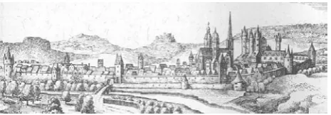
Figure 1: Herborn De Merian Hassiae by Matthäus Merian
1.3 Grave Coverings and Epitaphs
The coverings of crypts in sacral spaces are important references of history. We have to differ between figurative tombs, monuments and epitaphs. The latter are inscriptions fixed at the walls not straight at the place of burial. In its simplest shape an epitaph is a table with inscriptions of the name and dates of live of a person. Later in the 16th and 17th century the request for more representation leads to more figurative decoration.
A forthcoming exhibition should remember and tell about the persons and their work by presenting the epitaphs. As there is no possibility to show the originals, photogrammetric based recordings were carried out to produce textured virtual models.
Figure 2: Evangelic Town Church Herborn
2. PHOTOGRAMMETRIC RECORDING 2.1 Material and Environment
The items to be recorded consist of cast iron and black polished marble. Under the existing light conditions it is a challenge to photography and illumination. Due to the illustration of the fine textures in the marble it is obvious that an image texture from high resolution photographs is mandatory. Applying the structure from motion method provides a very flexible exposure arrangement particular under the unfavourable light environment. Manipulation of texture maps and artificial light settings for the renderings may compensate the difficult conditions on site.
Figurative depictions are most often made from sandstone and are much easier to photograph. For this kind of items we focus as well on solid modelling for 3D printing of replicas. A 2D representation will be provided by orthophotos.
Even economic aspects are important. The structure from motion method does not require a costly camera platform or lighting equipment to receive high quality pictures. The final illustration will come from the processing of several images together. For all the editing and manipulation of the image material open source or freeware is available.
2.2 Camera Operation via Smartphone
The photogrammetric images were taken by a mirror less Micro-Four-Thirds (MFT) Olympus Pen E-P5 camera. The 4/3'' CMOS sensor of this camera is sized 17,3 mm x 13,0 mm with a resolution of 4608 x 3456pixel. Due to the large amount of exposures and for a faster treatment the frames are stored in JPG format instead of RAW images.
With regard to the positioning two major features of the camera may be announced. That are the inclinable display and the WLAN function. While in live view a smartphone can be used to control the camera operation by using the Olympus Image Share application.
Free positioning of the camera mounted on a monopod can be carried out while viewing the image on the smartphones display. Initializing the remote control function on the touch screen of the camera and recording the QR code with the app
connects the devices to the WLAN. Most of the major camera functions can then be released via the smartphone, as shown in figure 3. If the camera can be directly operated, the inclinable display is useful. An optional viewfinder for this operation is not suitable.
Figure 3: Olympus Image Share
2.3 Exposure Arrangement and Registration
Exposures from the epitaphs were taken in three rows of half circles. The arrangement is horizontal from the centre and from the bottom and from the top with positive or negative inclination. An object with the size of approx. 1 m x 2 m can be covered in this way by approx. 18 exposures.
Some artificial markers had been fixed outside the objects as reference points for absolute orientation and receiving a true scale. The 3D paper targets are very light and positioned in horizontal or vertical layout against others. One has to take care that the targets are not hidden in oblique photos by the object. Further on it is important to remove the targets after the job without any slight damage of the walls.
Applying 123D Catch from Autodesk for reconstructing the image arrangement and building the mesh enables the assignment of reference points by identifying them in the images after the reconstruction. Clicking a point in one image enables automatically detection of corresponding points in the other images. The process is supported by epipolar line identification. Single points can be used for coordinate system definition or scaling, see figure 4. Use of the targets in other software is similar.
Figure 4: Target identification in 123D Catch
3. MESH GENERATION WITH SFM SOFTWARE With respect to the publication of Microsoft Photosynth in 2008 the development process of structure from motion software played an important role in universities and industry. Today the software products can automatically produce 3D meshes from photographs. A Smartphone or a camera and the software offer an alternative to 3D scanning.
Structure from motion distributions come in different flavors. We may group them into freeware, open source and proprietary license models. Platforms are Windows, Linux and also smartphones. One important criterion is the offline or online operation. Numerous papers on SfM are already published. Despite SfM evolved as a standard tool for 3D reconstruction we took the opportunity to compare some of the tools and did some quality check by comparing the meshes applying the Cloud Compare software, see figure 5. The distributions differ from each other by the above mentioned points and slightly in some functions like use of coded targets, scaling, camera calibration and by the feature of mesh processing. All the generated point clouds were more or less sufficient and provided a good accuracy.
The list of test candidates was:
o 123D Catch
o Recap 360
o Agisoft Photoscan
o Visual SfM
o Visual SfM + SURE
o 3DF-Zephyr
We could not cover the complete list of available software packages. The criteria for ranking the products are too complex to give an objective statement for the ease of use and quality of the software. A user himself has to find out the software that best fits to his application. In any case there will be a request for some further processing, as described below. Should the mesh be prepared for 3D printing or distributed as a virtual model via the internet? Sometimes a You Tube video stands at the end of the production chain.
Figure 5: Result comparison with Cloud Compare
Mesh processing software like MeshLab and 3D printing tools have to be applied at the end of the working chain. Recommended tools are Meshmixer and Netfabb Studio. Both
packages are excellent preprocessors for 3D printing. A particular focus will be directed to Blender as an engine for the production of true orthophotos with high resolution photo maps textured in best possible light environments.
4. MESH PROCESSING AND RENDERING 4.1 Mesh Processing and 3D Printer Tools
As a result of a SfM process a surface mesh is coming out. That mesh is a kind of a raw file. In some cases the orientation of the coordinate system and the scaling becomes necessary. Further on holes must be closed to receive a watertight mesh. Data reduction and smoothing of the surface have to be considered. The procedure of registration, sometimes called alignment, mounts separate meshes together. If a 3D print is intended, not only a watertight mesh is a condition. A model must be hollowed out. Finding the thinnest and thickest possible wall dimension must take in consideration the printing material. Figure 6 illustrates one of the 3D prints, here as a stereoscopic image pair. It is obvious that the mesh must be transformed into a solid before printing.
Meshlab is the ultimate tool for solving the foremost referred tasks. Meshmixer and Netfabb are also recommended for finishing the models and pre-processing for printing. The modelling process will be supported to a certain extend by Blender, the major open source 3D software for rendering and animation, as well. Each user has a favourite on one’s own. A combined application of the available tools from the box promises success.
Figure 6: Stereoscopic image pair side-by-side
4.2 Rendering with Blender
Blender is often accused for its uncommon user interface. Since version 2.7 the GUI comes with some improvements. A geometric object (a textured mesh) will be imported by File > Import > Wavefront > Obj. On the left side of the Blender application window we have now the vertical tool tabs for calling the toolbars with the panels that provide access to the particular operations. We select Create and the panel Light offers light sources for point light, sun, hemi light and area light. In the main window one can find the 3DView with the render properties. This window can be divided in top view, front view and left view. So the control of inserting or moving objects is much easier. In object mode the 3D cursor has to be positioned and the lights and the camera must come in first. Usually we set two area lights and a hemi lamp to receive a uniform light distribution over the object.
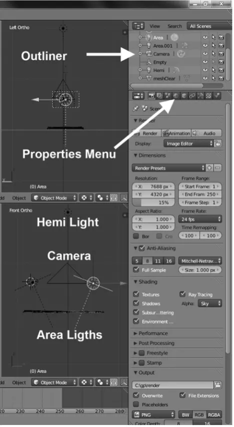
Now we can find on the right side of the screen the so called outliner. That is a scene tree for selecting the objects for sharing the render process. Located underneath is the properties menu. Here one can find the properties settings for camera, lights, geometry and the render button as well. If according to the geometry of the surface mesh lights and camera are positioned well, the render process can begin. First a low resolution speeds up the rendering. Settings for various light properties should vary only in one parameter for observing its influence. The major task in this step is finding the correct illumination and camera position.
Figure 7: Rendering applying Blender
Figure 7 displays the right menu area of Blenders GUI. One can detect an active area lamp, its position, direction and illumination. Finally we set the resolution to the requested high value, the camera type as orthogonal projection and save the image. Our result is a true orthophoto with nearly perfect illumination. Manipulations on radiometric values can be taken in advance with the incoming image atlas or with the final rendering. The short introduction here is given to encourage people in using the powerful blender render engine.
A few remarks about the resolution follow. The dimension of a table with an inscription is approx. 60 cm x 180 cm and takes between 20 and 40 lines of text. Assuming a print scale 1:1 comes to a resolution of 3500 x 10600 pixel using 150 dpi. On the other hand is a full HD resolution not enough to work out all the details.
5. RASPBERRY PI IMAGE PRESENTATION 5.1 Hardware and software configuration
There are alternatives existing in displaying the virtual grave plates: large format print media, digital projection or video presentation on monitors. The quality of a computer representation has additional advantages against print media. The digital media provides animation, interaction and superimposition of text. Taking into account the infrastructure of a very small exhibition facility, an individual solution with the following conditions may be installed:
o Full HD monitor o Raspberry Pi Computer
o Operation without keyboard and mouse o Minimum interaction
o Simple software solution – open source
The demands on the software are very low. The images should be animated from top to bottom and superimposing lines of text must be provided. A minimum interaction for changing the screen content should be included.
The widespread language Python as an open system offers numerous application libraries. With the Python Image Library is a system for graphic applications available. And Tkinter is the Python interface to the standard TK GUI toolkit, a platform independent tool for programming graphical interfaces. Linux and the single board computer Raspberry Pi together correspond to a low budget restriction. The question about the performance of this computer gnome is already answered. Raspberry Pi works as a media server under XBMC and with PiPresents is a sophisticated presentation package available. Since there are already 7 million items of the Raspberry Pi sold, writing about hardware details can be skipped here. Figure 8 supplies information about the size and components on the board. While writing this paper, a faster version 2 followed versions A/B. In any case will an installation benefit from low power consumption and the very small space needed.
Figure 8: Raspberry Pi SoC computer
A more important question is to ask for the acceptance by the operating stuff. In the final state the operation should be limited by two functions only: power on – power off.
In the first software version a kind of a digital frame is realized. A very low functioned GUI Interface contains continue/pause buttons, a one row list box to select the items to be displayed and an exit button. Data structure is very simple. The software reads the content from the directories and fills the list box elements. Figure 10 is a screenshot from the beta version; this sample can be viewed in operation under YouTube. Details and source code is available from www.divide-by-zero.com.
5.2 Setting up the Linux environment
There is a (half) headless system, monitor but no keyboard or mouse in planning. The system should fulfil the following requirements:
o Auto login as a standard user no password o Monitor in portrait mode
o Full screen with no decoration o Screensaver off
o Software auto start
o VNC Server
o Simple computer remote
Figure 9: Screenshot of image presentation
With sudo raspi-config the default login can be switched to user pi without password entry. Set display_rotate = 1 in /boot/config.txt to rotate the monitor into portrait mode.
Openbox is the standard window manager for the LXDE environment. The file /home/pi/config/openbox/lxde-pi-rc.xml has a tag applications, embedded in this tag is another tag
application with the attribute class=Tk. Here one can set the
values for full screen operation. The easiest way to switch off the screensaver is to install xscreensaver with sudo apt-get install xscreensaver and disabling it by the settings. Starting the application software during booting needs a .desktop file in /home/pi/.config/autostart.
The VNC Server and the simple computer remote server are tools for administering the Raspberry via a PC or to use the smartphone as keyboard and mouse. This may be necessary in case of request to repair something. Details to the above mentioned preparation of the OS environment can be downloaded as well as the application code from www.divide-by-zero.com. After this preparation the system is ready for reboot and starts with the beta-version software as can be seen in figure 10.
5.3 GPIO Interface
Selecting a topic from the software list box, as can be observed in figure 9, should be replaced by pressing rugged push buttons on an extra console The Raspberry Pi is equipped with a GPIO interface. The general purpose input/output provides 26 pins for reading and writing to a connected circuit.
During test phase a breadboard carries simple circuits with push buttons, resistances and a LED indicator. The breadboard is connected to the GPIO by a ribbon cable and a GPIO cobbler. The elements are linked to the GPIO pins and the 3,3 V line with breadboard wires. The prototype in figure 10 uses the blue and red buttons for counting the pushes, the yellow button quits the application and the LED responses optical to a button switch.
Figure 10: Prototyping the electronis of push buttons
The software again is written in Python and requires import of the RPi.GPIO library, the time library also and must be running under super user rights. A part of the code reads as follows:
#!/usr/bin/python #
import RPi.GPIO as GPIO import time
#
keyA = 11 led = 22 countA = 0
#
GPIO.setmode(GPIO.BOARD)
GPIO.setup(keyA,GPIO.IN,
pull_up_down=GPIO.PUD_DOWN) GPIO.setup(led,GPIO.OUT)
#
while True:
if (GPIO.input(keyA)==True): countA=countA+1 GPIO.output(led,True) time.sleep(.5)
else:
GPIO.output(led,False)
time.sleep(.1)
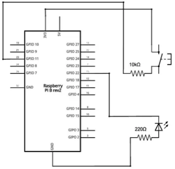
After importing the libraries the pin numbers for keyA and the LED are defined. The GPIO mode is set to BOARD and the keyA is declared as input and a push button. The LED connection is declared as output. During the endless loop keyA will become True if pressed and the LED output becomes True for 0.5 seconds. In this time the LED illuminates. If not pressed the LED is off and the loop is still running. Figure 11 is the schematic diagram according to the Python code. This very simple circuit demonstrates the convenient handling of the Raspberry GPIO via the Python language by the GPIO Library.
Figure 11: Schematic diagram for reading push buttons
Next step will be continuing the software development by integrating the prototype push button code into the application program. Afterwards the test phase starts with particular focus on suitability for long time running, handling by stuff and acceptance by visitors. If the test ends successful, the project will go on with the production of furniture for carrying the ragged push buttons, monitor, power supplies and computer.
CONCLUSION
In the present application true-orthophotos from more or less plane objects were produced with the SfM method. Instead of classic photography advantages appear in higher resolution and more flexibility in camera positioning and lightning. Further on the digital 3D model enables stereoscopic imagery, 3D printing and provides true scale drawings for investigations by the
conservator. Camera operation on site was supported by a smartphone remote control app.
Blender, the open source rendering and animation software, was applied for correcting insufficient light in the textures and output of high resolution orthographic projections.
Finally the presentation in an environment of small exhibition facility was discussed. Focusing on small equipment, saving power and related to budget questions the single board Raspberry Pi computer should drive the screens without keyboard or mouse available. Some interactivity should be provided by operating rugged push buttons. The handling for the museum's personal should be as easy as possible. One switch for power on-off operation should be enough.
A small viewer designed in compliance with the demands of this particular project developed in Python is running under Linux. The OS environment has to follow the regulations of a headless system.
Some Linux setup and Python programming was introduced. Understanding the integration of push button operating needed some basic electronic introduction into the GPIO interface.
REFERENCES
Böhm, G., J., 1993. Mittelalterliche figürliche Grabmäler in Westfalen von den Anfängen bis 1400. LiT Verlag , Münster
Immler, Ch., 2014. Linux mit Raspberry Pi. Franzis Verlag München
Pomaska, G., 2009. Utilization of Photosynth Point Clouds for
3D Object Reconstruction. XXII CIPA Symposium, Kyoto,
Japan
Pomaska, G., 2013. Monitoring the Deteriortion of Stone at
Mindener Museum’s Lapidarium. XXIV CIPA Symposium,
Strasbourg, France
http://www.divide-by-zero.com. Introduction into Python. Download source-code
http://www.imagefact.de/epitaphs. Website about the documentation of epitaphs and monuments
http://www.youtube.com/watch?v=hos-OOnUPoc. Screen recording of the beta version software