SURVEY PROBLEMS AND REPRESENTATION OF ARCHITECTURAL PAINTED
SURFACES
Marco Carpiceci a
a Dept. of History, Drawing and Architectural Restoration, SAPIENZA University of Roma, Italia – [email protected]
KEY WORDS: Survey, conservation, two-dimensional representation, painted surfaces, projective transformations, analytical processing.
ABSTRACT:
The painted surfaces of a building are generally vertical walls and flat roofs or arched roofs. The detection of these objects must be prepared according to the reason why the metric operation is designed; metric control of the whole performance practice is crucial for the result to matches the predetermined needs.
It's now clear that the acquisition of metric data, as the whole process of detection, can certainly not be left to an unidentified automation.
The mere representation of point clouds transformed in mesh and processed into 'maps' can cover only a few limited requirements. Conservation and restoration also require the transformation of “discrete” three-dimensional data into two-dimensional representations, resulting in geometric transformations that require a new mindset, especially considering hardware and software potential.
We want to propose a new type of projection end analysis as base for the development of representation systems that will transform three-dimensional models in two-dimensional projections for the conservation and restoration.
1. INTRODUCTION
1.1 Premise
A notepad and a pencil are not sufficient to draw a good painting; what is needed is hand and brains.
Similarly, a laser scanner and a good software are not enough for a good survey; what is needed is, brains, experience and knowledge of the object.
It could seem obvious, but the architectural survey is not a simple metric operation, but a real critical action. The architectural survey is composed of two main data structures: the first consists of the metric data, which include all those operations that take to the physical knowledge of the object, meaning geometrical features, physical composition, color. This is inserted and completed by the historical knowledge of the object. The second data structure consists of all those processes that tend to explain and better understand the object, so it is the real critical action towards the object; “critical” as result of data processing in order to achieve greater and wider knowledge. Even the seemingly simple operation of recording a painted surface has several complex operations which is best to analyze in order to better control their development and thus obtain better results.
More generally the acquisition of metric data requires the operator to priorly analyse and subsequently “discretise” what he wants to measure.
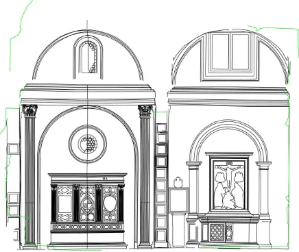
This happens in direct detection, but of course also by laser scanning; this way the “choice” has only been postponed but not eliminated. The same thing happened with photogrammetry; shooting was done, frames were oriented, and then points, lines and surfaceses were drawn in three dimensions, according to the stereoscopic model (actually … the surfaces were a problem). However, the photogrammetric representation was performed in post-production with analytical photorestitutor and CAD software (Fig. 1).
Figure 1. Italy, Naples, Monte Oliveto, Chapel of the Nativity, photogrammetric, M. Carpiceci 1990.
Today, the cloud of points, or processed and rendered mesh, is only a first step from which to start afterwards for the necessary next process (Fig. 2).
To think that a laser scanning corresponds to a survay is like mistaking a photograph with a pencil portrait.
Figure 2. Türkei, Sahinefendi, XL Martyrs Church, Laser Scanning, M. Carpiceci 2007.
1.2 The survey of the painted surfaces
The object is generally represented by a coating surface on which color is applied. So we need to record both metric data and color data.
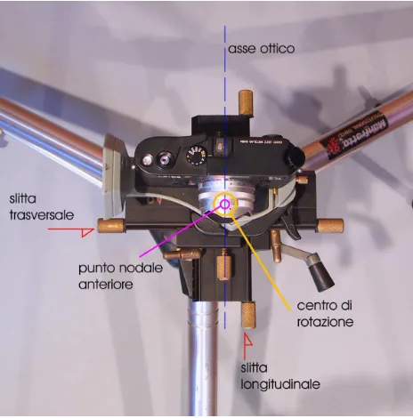
Figure 3. Seeking the position of the Front Nodal Point: center of rotation for panoramic shots.
The metric data can be acquired through precise measurement of the characteristic elements of the given shape with the help of a topographic station equipped with a laser rangefinder, or with two stations operating by forward intersection throughout space. More generally it can be achieved by laser scanning but necessarily integrated by those specific points which cannot be included with precision in the scanning grid, for how dense it may be.
This method, however, gives problems of accuracy and reliability of data related to the physical nature of those surfaces
such as metal, stone, wood, mirrored surfaces, curved surfaces, edges, etc. ..
The color data is necessarily acquired from color photographs. As it already was for the film, also sensors (CMOS or CCD) have a precise definition, a format, a latitude of exposure, a speed rating and e color range. Moreover, the lense used has its own angle of view, its focal length, its brightness and then a specific behavior according to the focusing, to the diaphragm, to the color deformation and to the sphere deformation. Also, chromatic reference must be provided on the photography by applying a chromatic scale on the subject.
For pseudo-spherical (or cubic) images, it is also needed to use a suitable pan and tilt head and the exact location of the center of rotation for the resumption of frames (Fig. 3).
1.3 The representation of the painted surfaces
The simple display of color data and metric data certainly allows virtual navigation within recorded environments. For both clouds of points with meshes and maps, and spherical landscapes, the software on the market and those (few) open source softwares are able to accurately show the architecture in their formal appearance and color.
Things get pretty complicated when from data we want to obtain 'executive' representations; that is, representations meant to operations such as the restoration or conservation. In this case we usually need two-dimensional riductions that can show the identified surfaces metrically. (Fig. 4).
Figure 4. Italy, Fondi, San Magno church, photomap of the northern transept, M. Carpiceci 2008.
The landscape of the softwares on the market does not extend beyond flat surfaces. Homographic straightening is the only possible metric script.
Till now, I have seen no specific studies on the problems of two-dimensional projections of painted surfaces that are not geometrically developable, nor on softwares for the development of striped surfaces.
2. SURFACES AND THEIR DEVELOPMENT
2.1 The surfaces
In general, at present, there are two fundamental approaches to architecture, which integrate and blend into the practice of survey. The first is the 'geometrical' approach: the perceptual and cognitive analysis of architecture's geometrical genesis. The second one is the “numerical” approach: the precise quantization of the discretized elements.
Let's try, then, to draw up an initial list of the common geometric shapes that we usually represent.
The first type will certainly be vertical surfaces:
- Flat vertical walls, or referable to flat surfaces with minimal changes;
- Curved or circular vertical walls, or referable to a sequence of circular or cylindrical sections, consisting of ruled surfaces, that means with vertical generatrix and circular directrix.
Extremely important is to acknowledge the need of controlling metric precision as well as recognizing geometric shapes that are always the developing shape in architecture. So, even if, metrically, there will never be a perfectly flat or cylindrical surface, the detector will decide weather to assimilate a certain sufrace, or part of it, to a flat area or to a cylinder.
For what concerns roofing surfaces, we can divide them into: - cylindrical roofings, such as barrel-vaults, cross-vaults, pavillon-vaults, lunettes, surfaces or parts of surfaces describable with parallel generatrixes and circular directrixes. - Conical roofings, surfaces or parts of surfaces describable with converging generatrixes and circular directixes;
There also are, though, other surfaces that need more attention, such as those that we can't represent in two dimensions: - spherical roofing surfaces, apse basins, vaults, spandrels; - concave and convex generical curve surfaces;
- concave and convex polygon surfaces.
2.2 The development of ruled surfaces
The development of this kind of surfaces does not involve any deformation of the surface's shape and so the result will be a perfectly two-dimensional representation in keeping with the three-dimensional object.
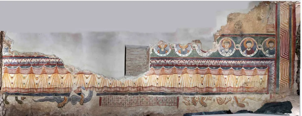
Leaving aside the case of the flat surfaces, ruled surfaces that belong to cylindrical sectors will be identified by three parallel generatrixes, the tracking of one of tem by a point perpendicularly to the other two, and then finding the circulare directrix (circumcenter of the triangle of the specified points). The transformation occurs perpendicularly to the generatrixes and their distance is related to the radius of the directrix (Fig.5).
Figure 5. Italy, Fondi, San Magno church, apse, development of the cylindrical surface, M. Carpiceci 2008.
In a circular sector of angle 'a' (in radians) and radius 'r', the developed tract, straight, will have length.
x = r * α
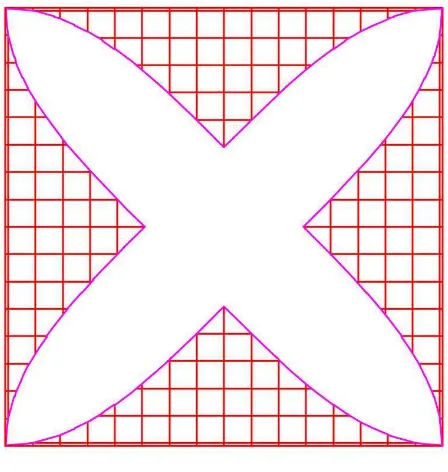
In the case of cross-vault we will need to develop a flat rappresentation with the nails joined together only by their outside edges (Fig. 6). For the pavillon-vault the developed spindles will share the key of the vault (Fig. 7).
More complex vaults will require several separate representations (not overlapping), but side by side so as to not to lose control of the continuity of the three-dimensional original three-dimensional shape. The lunettes will be, for example, represented close to the developed barrel-vault.
Speaking of the 'linear extrusion' surfaces (surfaces with parallel generatrixes), we could be in the case when the directrix is not a circle, although curved. It will then be necessary to break down this curved line in a sequence of circular tracts with no interruption, that means that two adjacent circular tracts should have the same tangent in the point in common. The number of
Figure 6. Development of the cross-vault.
Figure 7. Development of a pavillon-vault.
For the conical surfaces we need three converging generatrixes in order to identify the shape. We find the common point 'V' and then three points at the same distance 'l' from 'V'. The circular directrix of the straight cone to which the three generatrix belong to will pass through these three points. For the three points will the circular right directrix of the cone to which belong the three generatrix. The axis of the cone will be the line joining the center C of the directrix with V. The angle 'b' of half-opening of the cone will be given by the function:
β = arc sin r/l that for 'l' unitary simplifies to
β = arc sin r
The developed conical surface, unlike the cylindrical surface, can be parameterized in polar coordinates 'l' (distance from the center V) and 'a' (Angle on the circle of radius l).
Figure 8. Development of the time conical-vault.
In summary, so, we have the following angles:? Half-opening angle of the cone; opening angle of two generatrixes from the directrix; b angle (angle parameter) between the generatrixes developed in two dimensions (Fig. 8).
The arc length on the directrix is: x = r * α ie
x = l * sin β
which must necessarily be equivalent to the arc of the developed area:
x = l * γ where:
γ = sin β * α
2.3 Spherical surfaces and generic surfaces
The representation of this type of surface generates, of course, many problems and we want to suggest some solutions that will be confirmed in a future development of this research.
Starting from the more general problem we must necessarily assume two types of representation: a first general type includes the totality of the area or series of paintings; a second type that analyzes only a single item or box. While in the general view the conformity (the real shape) of the representation with the object is not necessarily required, in the local representation the exact formal corrispondence can be approached, with good approximation.
So there may be different concepts of projective transformation and/or analytical transformation to be considered in each case.
Let's consider an apse basin. From the geometrical point of view we will have this as a spherical top, continuation and termination of the cylindrical surface below. From the pictorial point of view it could be completely separate and therefore we do not need a joint flat representation.
Figure 9. Unfolding of the apse with the cylindrical surface and spherical basin.
A type of representation may be one that transforms the spherical surface in a continuation of the cylindrical one, thinking the basin formed by parallel vertical arcs, continuation of the cylinder's vertical generatrixes, which will be concentric semicircles in a two-dimensional representation. This way we keep the correspondence of dimension along the radial directions, and the radial ones will increase the more their distance from the center will increase, thus increasing the deformation of the represented shapes (Fig. 9).
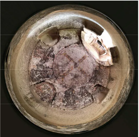
A similar application could be made for the dome, thinking the semi-sphere described by meridians and parallels, and thus maintaining linear dimensions on the meridians, so that the deformation will increase while getting closer to the equator (Fig. 10).
Prendendo spunto dalle proiezioni cartografiche, altri tipi di proiezione possono fornire un risultato più soddisfacente dal punto di vista percettivo ma, come sappiamo, non potremo certamente ottenere mai una rappresentazione conforme.
Inspired by map projections, other types of projection can provide a more satisfying result from the point of view of perception, but, as we know, we can never get a representation in keeping with the area.
3. A NEW APPROACH
A suggestion on a way of proceeding can be found in solid geometry. Richard Buckminster Fuller in 1946 already had the brilliant idea of applying the principle of the development of the platonic polygons to cartography.
Figure 10. Türkei, Keslik, S. Stephen church, apse, polar projection, M. Carpiceci 2009.
In 1954 he improved the projective system in Dymaxion Map of the world: the geographic representation of the Earth through the development of the icosahedron. A simple and effective principle, the earth's surface is projected on a concentric icosahedron, and it is developed in order to preserve the continuity of the land above seas (Fig. 11).
Figure 11. Dymaxion map of the world, Richard Buckminster Fuller, 1954, development of the Earth on the icosahedron.
Starting from the Dymaxion we can think to project the paintings of the inner surfaces of the domes on a cpmgriemt polyhedral surface and then develop it. The result is a representation which is, although not entirely congruent, very close to the shape of the original object.
As the number of faces of the polyhedron increase, the separations increase and sowe can't get a complete and continuous representation. However, by diminishing the number of faces we will increases the deformation in the joining points. The icosahedron is, among the platonic polyhedra, the shape that suits the best, with its 20 faces; for this form of development, the dodecahedron is also to test.
Figure 12. Development of the truncated icosahedron.
According with the object, also the use of Archimedean polyhedra will be tested. Among them we can identify three types:
the truncated icosahedron composed of hexagons and pentagons, with 32 faces, obtained by the intersection of the dodecahedron with its dual, the icosahedron (Fig. 12);
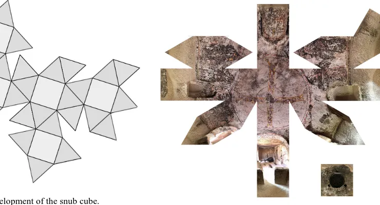
snub cube, composed of squares and triangles, and with 38 faces, 32 triangles and 6 squares (Fig. 13);
and rhombicuboctahedron, also composed of squares and triangles with 26 faces, 18 squares and 8 triangles.
Figure 13. Development of the snub cube.
Another possible application development will be experienced by bringing into architectural representation and survey of the theories developed in cartography by Jarka J. van Wijk with his Myriahedral Projections.
This form of development lsuits well our purpose.
Even with particularly complex inner surfaces such as painted caves, there is the possibility to track boundary lines among the painted scenes along the three-dimensional model, and then get a 'controlled' development, after we have previously chosen what has to be separate and what has to be kept united.
In this software model, the operator should have available a mesh surface on which he can track boundary lines and joining areas.
Again, if we need to remind it, we cannot think of the architectural survey and rappresentation performed with an automatic structure, it's a critical action, of thought and analysis, a tool used by thought.
3.1 References and Bibliography
Buckminster Fuller Institute, 181 N 11th Street, #402, Brooklyn, NY 11211, 718-290-9280 - http://www.bfi.org/
Docci, Mario; Maestri, Diego, 1994. Manuale di rilevamento architettonico e urbano, Laterza, Roma-Milano.
Fondelli, Mario, 1992. Trattato di fotogrammetria urbana e architettonica, Laterza, Roma-Bari.
Marks, Robert; Fuller, R. Buckminster, 1960. The Dymaxion World of Buckminster Fuller, Reinhold Publishing Corp., New York.
Solaini, Luigi; Astori, Bruno, 1981. Fotogrammetria, Clup, Milano.
van Wijk, Jarke J., 2008. Unfolding the Earth: Myriahedral Projections, “The Cartographic Journal” Vol. 45 No. 1 pp. 32– 42 February 2008.
http://www.ingentaconnect.com/content/maney/caj
Figure 14. Türkei, Keslik, S. Stephen church, apse, unfolding of the projection on rhombicuboctahedron, M. Carpiceci 2009.