• Tidak ada hasil yang ditemukan

Chapter 1 • Introduction - Solution Manual Fundamentals of Machine Elements 2nd

N/A
N/A
Protected

Academic year: 2019

Membagikan "Chapter 1 • Introduction - Solution Manual Fundamentals of Machine Elements 2nd"

Copied!
461
0
0

Teks penuh

(1)

Chapter 1 • Introduction

1.1

Design transport containers for milk in 1 gallon and 1 liter sizes.

Notes: There are a number of design considerations that can be included in this problem. Some examples are considered here, but the student should not be restricted in the types of solutions pursued. This type of problem is an excellent opportunity for brainstorming, where a group is encouraged to provide all possible answers to the problem regardless of feasibility. For example, the materials considered could include wood barrels, ceramic jugs or foil or plastic bags, as in intraveneous fluid containers.

Solution:

The transport containers for milk should be easy to handle and store as well as being easy to pour from without spilling. The material should be recyclable or be able to be burned leaving harmless combustion products. The obvious material choices are paper or plastic materials, although glass bottles and metal cans can be considered as possibilities. For a one liter container the standard type Pure Pac or Tetra Pac Bric made of plastic carton is a good design.

A one gallon container has to be compact to be easily stored in a refrigerator. The width, depth, and height should be similar in size, which would be about 156 mm x 156 mm x 156 mm. That size is too large to grip with one hand. Therefore, a one gallon container is preferably made of a plastic with an integral handle.

1.2

Design a simple coat hanger to be used by dry cleaners. It should be able to accommodate both a winter coat and a pair of trousers. It should function well but also be as

inexpensive as possible. Notes: See the notes to problem 1. Solution:

If they are not hung simultaneously, a steel wire frame of triangular shape with a hook at the top could be used. The horizontal portion could be covered with a high friction coating or tape or glue to keep the trousers from sliding off.

For coats, a sturdier frame is needed, requiring either a larger gage of wire or pursuit of another alternative such as wood or plastic hangers.

1.3

Journal bearings on train boxcars in the early 19th century used a “stink additive” in their lubricant. If the bearings got too hot, they would attain a noticeable odor, and an oiler would give the bearing a squirt of lubricant at the next train stop. What design philosophy does this illustrate? Explain.

Solution:

(2)

one component, in this case a bearing, is imminent, then extra maintenance on this bearing is justified by the principal of uniform safety.

1.4

A safety chain is used in automotive towing applications. Which design philosophy is being incorporated into the towing system design?

Solution:

Since the safety chain is used in addition to the towbar, it is an example of redundancy, and it is a passive system. Furthermore, it is an example of a fail-safe design, because if the towbar fails, the towed vehicle will follow the car and will not swerve into other lanes and collide with other vehicles.

1.5

A hand-held drilling machine has a bearing to take up radial and thrust load from the drill. Depending on the number of hours the drill is expected to be used before it is scrapped, different bearing arrangements will be chosen. A rubber bushing has a 50-hr life. A small ball bearing has a 300-hr life. A two bearing combination of a ball bearing and a cylindrical roller bearing has a 10,000 hr life. The cost ratios for the bearing arrangements are 1:5:20. What is the optimum bearing type for a simple drill, a semiprofessional drill, and a professional drill?

Notes: This problem is fairly subjective, but there should be a realization that there is an increase in expected life for a professional drill versus a simple drill. In fact, for certain users, a 50 hour life is probably sufficient.

Solution:

Notice that the cost per time is highest for the rubber bushing and lowest for the ball bearing cylindrical bearing combination. However, the absolute cost is higher for the longer lasting components, so the expected life must be assessed. Rough estimates based on expected lives are as follows.

a) Simple drill - use rubber bushingbearings.

b) Semi-professional drill - either two ball bearings or a ball and cylindrical roller bearing combination.

c) Professional drill - use a ball and cylindrical roller bearing combination.

1.6

Using the hand-held drill described in Problem 1.5, if the solution with the small ball bearing was chosen for a semiprofessional drill, the bearing life could be estimated to be 300 hr until the first spall forms in a race. The time from first spall to when the whole rolling-contact surface is covered with spalls is 200hr, and the time from then until a ball cracks is 100 hr. What is the bearing life

a) If high precision is required? b) If vibrations are irrelevent?

c) If an accident can happen when a ball breaks?

Notes: This problem is fairly subjective, but there should be a realization that there is a decrease in expected life for the high precision drill, etc.

Solution:

(3)

c) Depending on the severity of the accident, it is possible that an entirely different bearing should be used. However, safety allowances of 300-500 hours may be reasonable.

1.7

The dimensions of skis used for downhill competition need to be determined. The maximum force transmitted from one foot to the ski is 2500N, but the snow conditions are not known in advance, so the bending moment acting on the skis is not known. The weight of the skier and equipment is 100 kg. Estimate the safety factor needed.

Notes: There are two different approaches, that of section 1.5.1.1, and that of a worst case scenario.

Solution:

Using the approach of section 1.5.1.1, the largest safety factor from Table 1.1 is nsx=3.95, and the largest value of nsy from Table 1.2 is 1.6. Therefore, the largest safety factor, if there is poor control of materials and loading, and if the consequences are sever, is given by Equation 1.2 as:

ns=nsxnsy=(3.95)(1.6)=6.32

Another approach is to perform a worst case scenario analysis. If the weight of skier and equipment is 100 kg and the maximum load on the ski is 2500N, then the centrigugal acceleration is 23 m/s2. If the speed of the skier is 35m/s (126km/hr), the radius from the ski track will be 53 m. If the speed is 20 m/s, the radius is 17.4m. This means that no overstressing should ever occur due to bending of the ski, so the safety factor could be chosen just above one.

1.8

A crane has a loading hook that is hanging on a steel wire. The allowable normal tensile stress in the wire gives an allowable force of 100,000N. Find the safety factor that should be used.

a) If the wire material is not controlled, the load can cause impact, and fastening the hook in the wire causes stress concentrations. (If the wire breaks, people can be seriously hurt and expensive equipment can be destroyed.)

b) If the wire material is extremely well controlled, no impact loads are applied, and the hook is fastened in the wire without stress concentrations. (If the wire breaks, no people or expensive equipment can be damaged.)

Notes: Equation (1.2) is needed to solve this problem, with data obtained from Tables 1.1 and 1.2. Solution:

a). If the quality of materials is poor (A=p), the control over the load to the part is poor (B=p), and the accuracy of the stress analysis is poor (C=p), then nsx=3.95 as given in Table 1.1. If the economic impact and danger are both very serious (D=E=vs), then from Table 1.2, nsy=1.6. Therefore, the required safety factor is obtained from Equation (1.2) as

ns=nsxnsy=(3.95)(1.6)=6.3

b) If the quality of materials, the control over the load to the part, and the accuracy of the stress analysis are all very good (A=B=C=vg), then nsx=1.1 as given in Table 1.1. If the economic impact and danger are both not serious (D=E=ns), then from Table 1.2, nsy=1.0. Therefore, the required safety factor is obtained from Equation (1.2) as

(4)

1.9

Give three examples of fail-safe and fail-unsafe products.

Notes: This is an open-ended problem, and many different solutions are possible. Solution:

Examples of fail safe products are: 1) electric motors, which fail to move and cause no hazards when they fail. 2) Bowling pins, because of their distance from bowlers, do not present any hazards when they shatter. 3) Furniture upholstery, which causes aesthetic objection long before structural failure occurs. Examples of fail unsafe products include: 1) Bungee cords, as in bungee cord jumping from bridges and the like; 2) parachutes, which cause a fatal injury in the vast majority of failures, and 3) A fan on an exhaust hood over a fume producing tank, such as an electroplating tank. Failure of the forced air circulation system exposes plant personnel to harmful fumes.

1.10

An acid container will damage the environment and the people around if it leaks. The cost of the container is proportional to the container wall thickness. The safety can be increased either by making the container wall thicker or by mounting a reserve tray under the container to collect the leaking acid. The reserve tray costs 10% of the thick-walled container cost. Which is less costly, to increase the wall thickness or to mount a reserve tray under the container?

Notes: This problem uses the approach described by Equation (1.2) and Tables 1.1 and 1.2. Solution:

If the safety factor is unchanged, then for a thicker container wall, we see that with danger to personnel rated very serious and economic impact very serious (D=E=vs), then nsy=1.6. If a reserve tray is used, the required safety factor for the container (D=E=ns) is nsy=1.0. Therefore, if A is the cost of the container with thicker walls, then the cost of the container with a reserve tray is

A

1.6+

( )

0.1A=0.725A

Therefore, with the same safety factor, it is less costly to have the reserve tray.

1.11

The unit for dynamic viscosity in the SI system is newton-seconds per square meter, or pascal-seconds (N-s/m2 = Pa-s). How can that unit be rewritten by using the basic relationships described by Newton’s law for force and acceleration?

Notes: The only units needed are kg, m, and s. Solution:

By definition, a Newton is a kilogram-meter per square second. Therefore, the unit for dynamic viscosity can be written as:

Ns m2 =

kgm s2   

  

s m2 =

(5)

1.12

The unit for dynamic viscosity in Problem 1.11 is newton-second per square meter (Ns/m2) and the kinematic viscosity is defined as the viscosity divided by the fluid density. Find at least one unit for kinematic viscosity.

Notes: The only units needed are m and s. Solution:

The units for kinematic viscosity can be written as:

ηk = ηρ=

Ns m2   

   kg m3   

  

= Nsm kg =

kgm s2   

   sm kg =

m2 s

1.13

A square surface has sides 1m long. The sides can be split into decimeters, centimeters, or millimeters, where 1m=10dm, 1dm=10cm, and 1cm=10mm. How many millimeters, centimeters, and decimeters equal 1m? Also, how many square millimeters, square centimeters and square decimeters equal one square meter?

Notes: This is fairly straightforward; Table 1.3(b) is useful. Solution:

From Table 1.3(b), one meter equals 10 dm, 100 cm and 1000 mm. Therefore, a square meter is: 1m2=(1000mm)2=1 million (mm)2.

1m2=(100cm)2=10,000 (cm)2 1m2=(10dm)2=100(dm)2

1.14

A volume is 1 tera (mm3) large. Calculate how long the sides of a cube must be to contain that volume.

Notes: From Table 1.3 (b), tera is 1 x 10¹². Solution:

A tera (mm3) is 1012 (mm3). Therefore, this volume is 1012mm3 1m

1000mm 

 

   3

=1000m3 A cube with this volume has sides with length of 10m.

1.15

A ray of light travels at a speed of 300,000 km/s=3 x 108m/s. How fast will it travel in 1 ps, 1 ns, and 1µs?

(6)

x=vt=

(

3×10⁸m/s

)

(

10−12s

)

=3×10⁻⁴m=0.3mm In one nanosecond, light travels:

x=vt=

(

3×10⁸m/s

)

( )

10−9s =0.3m=300mm In one microsecond, light travels:

x=vt=

(

3×10⁸m/s

)

( )

10−6s =300m

1.16

Two smooth flat surfaces are separated by a 10-µm thick lubricant film. The viscosity of the lubricant is 0.100 Pa-s. One surface has an area of 1 dm2 and slides over the plane surface with a velocity of 1 km/hr. Determine the friction force due to shearing of the lubricant film. Assume the friction force is the viscosity times the surface area times velocity of the moving surfaces and divided by the lubricant film thickness.

Notes This problem is simple if consistent units are used. Solution:

Rewriting terms into consistent units, 10µm=10-5m, 0.100Pas=0.100Ns/m2, 1dm2=(0.1m)2=0.01m2, and

1km hr =

1000m

3600s =0.2778m/s Therefore the friction force is given by:

F= η0Aub h =

0.1Ns m2   

 

(

0.001m2

)

(

0.2778m/s

)

10−5m =27.78N

1.17

A firefighter sprays water on a house. The nozzle diameter is small relative to the hose diameter, so the force on the nozzle from the water is

F=vdma dt

where v is the water velocity, and dma/dt is the water mass flow per unit time. Calculate the force the firefighter needs to hold the nozzle if the water mass flow rate is 3 tons/hr and the water velocity is 100km/hr.

Notes: A ton can be misperceived; in metric units, a ton is 1000kg, while in English units it is 2000 lbf. Since the units in this problem are metric, the metric interpretation is used. This problem is not difficult as long as consistent units are used.

Solution:

The velocity can be written as:

100km hr =

1 0 0 , 0 0 0m

3600s =27.78m/s The mass flow rate can be rewritten as:

dma

dt = 3tons

hr =

3000kg

(7)

F=vdma

dt =

(

27.78m/s

)

(

0.8333kg/s

)

=23.15N

1.18

The mass of a car is 1346 kg. The four passengers in the car weigh 65.55 kg, 75.23 kg, 88.66kg, and 91.32 kg. It is raining and the additional weight due to the water on the car is 1.349 kg. Calculate the total weight of the car, including the weight of the passengers and the weight of the water, using four significant figures.

Solution: The weight is

Wtot=1346kg+65.55kg+75.23kg+88.66kg+91.32kg+1.349kg±0.5kg=1668.109kg±0.5kg Therefore the total weight is 1668kg.

1.19

During an acceleration test of a car, the acceleration was measured to be 1.4363 m/s2. Because slush and mud adhered to the bottom of the car, the weight was estimated to be 1400±100kg. Calculate the force driving the car and indicate the accuracy.

Solution:

Since the force is given by P=maa, the force is given by

P=maa=

(

1400kg±100kg

)

(

1.4363m/s2

)

=2010.82±143.6N= 2154.45N 1867.19N 

(8)

Chapter 2 • Load, Stress and Strain

2.1

The stepped shaft A-B-C shown in sketch a is loaded with the forces P1 and/or P2. Note that P1 gives a tensile stress σ in B-C and σ/4 in A-B and that P2 gives a bending stress σ at B and 1.5σ at A. What is the critical section

a) If only P1 is applied? b) If only P2 is applied?

c) If both P1 and P2 are applied?

Notes: This solution will ignore advanced concepts such as stress concentrations that would exist at the fillet, since this material is covered later in the text. Similarly, the location in the cross section where the maximum stress occurs could be identified with the information in Chapter 4, but will be left for the student.

Solution:

If only P1 is applied, the critical section is the length B-C, since the tensile stress is highest in this section.

If only P2 is applied, the largest stress occurs at A.

If both P1 and P2 are applied, the maximum stress in section A-B occurs at point A and is σA=σ/4+1.5σ=1.75σ

The maximum stress in section B-C occurs at point B and is σB=σ+σ=2σ Therefore, the critical section is B-C, in particular point B.

2.2

The stepped shaft in Problem 2.1 (sketch a) has loads P1 and P2. Find the load classification if P1’s variation is sinuous and P2 is the load from a weight a) If only P1 is applied.

b) If only P2 is applied.

c) If both P1 and P2 are applied.

Notes: This solution uses the terminology on pages 30-32. Solution:

If only P1 is applied, then the load is cyclic with respect to time (see page 30), and is a normal load (see page 31).

If only P2 is applied, the load is sustained with respect to time, and is both a shear load and a bending load. However, for long columns, bending is usually more important than shear, so it is reasonable to classify P2 as a bending load.

If both P1 and P2 are applied, then the load is cyclic with respect to time (although the mean stress is not zero), and the loading is combined (see page 32).

(9)

EIy”=-M Where

E=modulus of elasticity, Pa I=area moment of inertia, m4 M=bending moment, N-m

y"=d2y/dx2=second derivative of y with respect to x, m-1 y=deflection, m

This gives a positive (tensile) stress in the fibers on the beam in the positive (y) direction. Find how the slope of the beam changes with increasing x coordinate for positive and negative bending.

Notes: The slope of the beam is the first derivative of the deflection, so one must integrate the given equation to obtain the solution.

Solution:

The slope of the beam is given by θ=dy/dx. Integrating the given equation, dy

dx = θ = − Mx

EI +C

Where C is a constant of integration, and reflects the effects of boundary conditions. If we ignore C, we can see that if the bending moment is negative, the slope of the beam is positive for positive x and negative for negative x. If the moment is positive, the slope is negative for positive x and positive for negative x.

2.4

A bar hangs freely from a frictionless hinge. A horizontal force P is applied at the bottom of the bar until it inclines 30° from the vertical direction. Calculate the horizontal and vertical components of the force on the hinge if the acceleration due to gravity is g, the bar has a constant cross section along its length, and the mass is ma.

Notes: This problem is straightforward once a free body diagram is drawn. Force and moment equilibrium is then sufficient to solve the problem.

Solution:

The free body diagram of the bar is as shown to the right. Since the bar cross section is constant, we can put the center of gravity at the geometric center of the bar. The reactions at the hinge have been drawn in red. Notice the absence of a moment reaction, since the hinge was expressly described as frictionless (this is a common assumption for hinges).

Most of the time, it saves time to perform moment equilibrium first, before applying force equilibrium. This is true here as well. Therefore, summing moments about the hinge point, Equation (2.2) gives:

M=0

=mag

l 2sin30° 

 

  −Plcos30°; mag=

2P tan30° Taking equilibrium in the x-direction, Equation (2.1) gives:

Px =0 = −Rx +P; Rx =P

= gma

(10)

Py =0 =Rygma; Ry=gma

2.5

Sketch b shows the forces acting on a rectangle. Is the rectangle in equilibrium?

Notes: To satisfy equilibrium, Equations (2.3) must be satisfied. Solution:

Taking the sum of forces in the x-direction,

Σ

Fx=30N-20N-10N=0

Therefore, equilibrium in the x-direction is satisfied. Taking equilibrium in the y-direction gives

Σ

Fy=-18N+20N-20N+18N=0

Therefore, equilibrium in the y-direction is satisfied. Taking moments about point A,

Σ

MA=(20N)(7cm)+(10N)(5cm)-18N(7cm)=64Ncm

Therefore, moment equilibrium is not satisfied, and the rectangle is not in equilibrium.

2.6

Sketch c shows the forces acting on a triangle. Is the triangle in equilibrium?

Notes: To satisfy equilibrium, Equations (2.3) must be satisfied. Solution:

Taking the sum of forces in the x-direction,

Σ

Fx=65.37N-40N(cos10°)-30N(cos30°)=0.00

Therefore, equilibrium in the x-direction is satisfied. Taking equilibrium in the y-direction gives

Σ

Fy=39.76N-17.81N-40N(sin10°)-30N(sin30°)=0.00

Therefore, equilibrium in the y-direction is satisfied. Taking moments about point A,

(11)

2.7

Sketch d shows a cube with side lengths a and eight forces acting at the corners. Is the cube in equilibrium?

Notes: For three dimensional equilibrium, Equations (2.1) and (2.2) must be satisfied. Solution:

Taking the sum of forces in the x-direction,

Σ

Fx=P+P-P-P=0

Therefore, equilibrium in the x-direction is satisfied. Taking equilibrium in the y-direction gives

Σ

Fy=P+P-P-P=0

Therefore, equilibrium in the y-direction is satisfied. There are no forces in the z-direction, so equilibrium is automatically satisfied. Taking moments about the z-axis,

Σ

Moz=Pa+Pa-Pa-Pa=0

Therefore, equilibrium about the z-axis is satisfied. Taking moments about the x-axis,

Σ

Moz=Pa-Pa=0

Therefore, equilibrium about the x-axis is satisfied. Taking moments about the y-axis,

Σ

Moy=Pa-Pa=0 Therefore, the cube is in equilibrium.

2.8

A downhill skier stands on a slope with a 5° inclination. The coefficient of friction between the skis and the snow is 0.10 when the ski is stationary and 0.07 when the ski starts to slide. Is the skier in static equilibrium when he is stationary and when he slides down the slope?

(12)

Solution:

A free-body diagram of the skier is shown to the right. The skier’s weight is mag, and the slope has a normal force as a reaction and a friction force which develops tangent to the slope. Summing forces in the direction normal to the slope yields:

Σ

F=N-magcos5°; N=magcos5° Taking forces tangent to the slope,

Σ

F=magsin5°-µN=magsin5°-µmagcos5°; µ=tan5°=0.08749

If the skier is stationary, the coefficient of friction is 0.10, and there is enough friction to keep the skier stationary. If the skier is moving, then the coefficient of friction is 0.07, so the friction force developed is not enough to maintain equilibrium. The skier will accelerate.

2.9

Given the components shown in sketches e and f, draw the free-body diagram of each component and calculate the forces.

Notes: For equilibrium, the force Equations in (2.3) needs to be satisfied. Assume there is no friction in sketch (e). In sketch f, moment equilibrium shows that the only possible force in each member is an axial force.

Solution:

The free body diagram for sketch e is shown to the left. Flat surfaces give normal reaction forces as shown. From Equation (2.3), and summing forces in the y-direction,

Σ

Fy=0=-W+N1cos30°+N2cos60°; N1=W/cos30°-N2(cos60°/cos30°) Summing forces in the x-direction,

Σ

Fx=0=N1sin30°-N2sin60°=(W/cos30°-N2(cos60°/cos30°))sin30°-N2sin60°; N2=0.5W Substituting into the x-direction equilibrium equation gives N1=0.866W.

The free body diagram for sketch f is shown to the right. For equilibrium in the x-direction,

Σ

Fx=0=P-P2sin30°; P2=2P=2.4kN Taking equilibrium in the y-direciton.

(13)

2.10

A 5-m-long bar is loaded as shown in sketch g. The bar cross section is constant along its length. Draw the shear and moment diagrams and locate the critical section.

Notes: In such problems, one must first obtain the reactions before generating the shear and moment diagrams. Also, it is useful to consider moment equilibrium first. In this problem, the shear and moment diagrams are obtained through the method of sections.

Solution:

The reaction forces have been added to the figure in red. Summing moments about the origin gives

Σ

Mo=0=10kN(2m)-Ay(3m)+3.2kN(5m);Ay=12kN Summing forces in the y-direction yields

Σ

Fy=0=-Oy+10kN-Ay+3.2kN; Oy=10kN-12kN+3.2kN=1.2kN

The method of sections described on page 39 is used to obtain the shear and moment diagrams. This proceeds as follows:

a) 0≤x<2m:

Σ

Fy=0=-Oy+V; V=Oy=1.2kN

Σ

MO=0=M-V(x); M=Vx=(1.2kN)x Note: at x=2m, M=2.4kNm

b) 2m≤x<3m:

Σ

Fy=0=-Oy+10kN+V;V=Oy-10kN=-8.8kN

Σ

MO=0=M-V(x)-10kN(2m); M=20kNm-(8.8kN)x

c)3m≤x:

Σ

Fy=0=-Oy+10kN-12kN+V;V=3.2kN

Σ

MO=0=M-V(x)-10kN(2m)+12kN(3m); M=-16kNm+3.2x

The shear and moment diagrams are plotted as follows:

From these shear and moment diagrams, it can be seen that the critical section is at point A.

2.11

A beam is supported by a wire in one end and by a pin in the other end. The beam is

loaded by a force parallel with the wire. What is the direction of the reaction force in the pin?

Notes: This merely requires an understanding of the equations of equilibrium. One of the

(14)

Solution:

Force equilibrium gives that the force in the pin has to be parallel with the wire since the wire can only transmit an axial force. Therefore, the force in the pin has to be in the same direction as in the wire.

2.12

Sketch h shows a simple bridge. The midpoint of the bridge is held up by a wire leading to the top hinge of the two equal beams. When a truck runs over the bridge, the force in the wire is measured to be 500,000 N. Determine the forces in the beams and the horizontal force component in the middle of the bridge.

Notes: This problem can be easily solved by drawing a free body diagram of one of the beams and then applying the equations of equilibrium.

Solution:

A free body diagram of the left beam is shown to the right. It is assumed that each beam takes one-half the load, as shown. From moment equilibrium, about the pin, it can be seen that

Σ

M=0=(250,000N)(lcos45°)-PH(lsin45°); PH=250,000N Therefore, the load carried by the beam is

Pbeam=

(

250kN

)

2+

(

250kN

)

2 =353.6kN

Taking force equilibrium in the horizontal direction gives

Σ

Fh=0=Rx-PH; Rx=PH=250kN This is the horizontal force component in the middle of the bridge.

(15)

Notes: In such problems, one must first obtain the reactions before generating the shear and moment diagrams. Also, it is useful to consider moment equilibrium first. In this problem, the shear and moment diagrams are obtained through direct integration, as suggested by Equations (2.4) and (2.5). The maximum stress is given by σ=Mc/I where I is the moment of inertia, given in Table 4.1 on page 148.

Solution:

Taking moment equilibrium about point A yields:

Σ

MA=0=(1kN)(0.2m)-By(0.5m)-(0.5kN)(0.64m); By=-0.24kN=-240N Vertical force equilibrium gives Ay:

Σ

Fy=0=Ay-1kN+By+0.5kN; Ay=1kN-By-0.5kN=0.74kN=740N

The shear and moment diagrams are constructed directly from the applied load, using Equations (2.4) and (2.5). Since the loads are simple, this approach allows simple integration. The diagrams are as follows:

As can be seen, the maximum moment is at x=0.2 and has the value of

Mmax=(740N)(0.2m)=148Nm. This is the area under the shear force curve, indicated in red. The moment of inertia of a round cross section is (see Table 4.1 on page 148, or the inside back cover):

I= πd

4

64 = π 0.05m

(

)

4

64 =3.068×10

−7

m4 The maximum bending stress in the shaft is:

σ = Mc I =

148Nm

(

)

(

0.025m

)

3.068×10⁻⁷m4 =12.06MPa

2.14

Sketch j shows a simply supported bar loaded with a force P at a position one-third of the length from one of the support points. Determine the shear force and bending moment in the bar. Also, draw the shear and moment diagrams.

(16)

Solution:

Moment equilibrium about point A yields:

Σ

MA=0=P(l/3)-By(l); By=P/3 Vertical force equilibrium gives:

Σ

Fy=0=Ay-P+By; Ay=P-By=P-P/3=2P/3

The shear and moment diagrams are obtained through direct integration and are shown below.

2.15

Sketch k shows a simply supported bar loaded by two equally large forces P at a distance l/4 from its ends. Determine the shear force and bending moment in the bar, and find the critical section with the largest bending moment. Also, draw the shear and moment diagrams.

Notes: In such problems, one must first obtain the reactions before generating the shear and moment diagrams. Also, it is useful to consider moment equilibrium first. In this problem, the shear and moment diagrams are obtained through direct integration, as suggested by Equations (2.4) and (2.5).

Solution:

Moment equilibrium about point A yields:

Σ

MA=0=P(l/4)+P(3l/4)-By(l); By=P Vertical force equilibrium gives

Σ

Fy=0=Ay-P-P+By; Ay=P

The shear and moment diagrams are obtained through direct integration and are shown below.

The largest bending moment occurs between the two applied forces and has the magnitude of M=Pl/4.

(17)

Notes: In such problems, one must first obtain the reactions before generating the shear and moment diagrams. Also, it is useful to consider moment equilibrium first. In this problem, the shear and moment diagrams are obtained through direct integration, as suggested by Equations (2.4) and (2.5).

Solution:

Moment equilibrium about point A yields:

Σ

MA=0=Pl+Byl; By=-P Vertical force equilibrium gives:

Σ

Fy=0=-P+Ay+By; Ay=2P

The shear and moment diagrams are obtained through direct integration and are shown below.

2.17

Sketch m shows a simply supported bar with a constant load per unit length w0 imposed over its entire length. Determine the shear force and bending moment as functions of x. Draw a graph of these functions. Also, find the critical section with the largest bending moment.

Notes: In such problems, one must first obtain the reactions before generating the shear and moment diagrams. Also, it is useful to consider moment equilibrium first. In this problem, the shear and moment diagrams are obtained through direct integration, as suggested by Equations (2.4) and (2.5).

Solution:

For the purposes of equilibrium, the distributed load can be replaced by a point load of magnitude w0l at the midpoint of the span. Therefore, moment equilibrium about point A yields:

MA=0=w0l l

2   

   −Byl

; By=

w0l 2 Force equilibrium in the vertical direction gives:

Fy =0=Ayw0l

+By; Ay=

w0l

2

(18)

It can be seen that the maximum moment occurs at mid-span. The magnitude of this force is the area under either triangle on the shear curve, as suggested by Equation (2.5). This gives

Mmax= 1

2.18

Sketch n shows a simply supported beam loaded with a ramp function over its entire length, the largest value being 2P/l. Determine the shear force and the bending moment and the critical section with the largest bending moment. Also, draw the shear and moment diagrams.

Notes: One must first obtain the reactions before generating the shear and moment diagrams. Also, it is useful to consider moment equilibrium first. In this problem, the shear and moment diagrams are obtained through the method of sections.

Solution:

The loading is described by

q x

( )

= −2P

In analyzing equilibrium, the loading is replaced by a force of magnitude P at a location of x=2l/3. Therefore, moment equilibrium about point A gives:

MA=0=P 2l

Vertical force equilibrium gives:

Fy=0= AyP+By; Ay =PBy = P

3

Taking a section at a location x in the span,

(19)

The maximum moment occurs when V=0, which occurs at: 0= P

3 − Px2

l2 ; x= l

3 Substituting this into the moment equation gives

Mmax= P

3 l

3   

   −

P 3l2

l 3   

   3

= Pl 3 3 −

Pl 9 3 =

2Pl 9 3

2.19

Draw the shear and moment diagrams, and determine the critical section for the loading conditions shown in sketch o. Neglect the weight of the bar. Let w0=100kN/m, P=5kN, M=2x10⁴N-m, and l=300mm.

Notes: One must first obtain the reactions before generating the shear and moment diagrams. Also, it is useful to consider moment equilibrium first. In this problem, the shear and moment diagrams are obtained through singularity functions. Table 2.2 on page 43 is useful for writing the load distribution in terms of singularity functions.

Solution:

For equilibrium reasons, the distributed loads can be replaced by point loads as shown below: Taking moment equilibrium about point A gives:

MA=0=

(

5kN

)

0.200m

3   

  +10kN

(

0.15m

)

+5kN

(

0.233m

)

By

(

0.2m

)

+5kN

(

0.3m

)

+20kNm

or By=22.6kN. Taking force equilibrium in the vertical direction gives:

Fy =0 =Ay −5kN −10kN−5kN +By −5kN;Ay= −2.4kN

Therefore, the load distribution can be written in terms of singularity functions as (see Table 2.2 on page 43):

q x

( )

=2.4kN x −1−1kN/m x

[

1− x −0.1m1

]

+22.6kN x−0.2m −1 +1kN/m x

[

−0.2m1− x −0.3m 1

]

−5kN x −0.3m −1 +20kNm x−0.3m −2 Therefore, the shear distribution is given by Equation (2.4) as

V x

( )

=2.4kN x 0−1kN/m

2 x

2 x0.1m 2 x 0.2m 2+ x 0.3m 2

[

]

(20)

M x

( )

=2.4kN x 1−1kN/m

6 x

3 x 0.1m3 x 0.2m 3+ x 0.3m3

[

]

+22.6kN x−0.2m 1−5kN x−0.3m1+20kNm x−0.3m0 The shear and moment diagrams are sketched below:

2.20

Redo problem 2.19 while considering the weight of the bar per unit length to be w0=5N/m.

Notes: This problem is useful after Problem 2.19 has been completed, since the statics then suggests the answer - that the beam weight is negligible.

Solution:

Taking moment equilibrium about point A gives: MA=0=

(

5kN

)

0.200m 3   

  −

(

5N/m

)

(

0.3m

)

(

0.15m

)

+10kN

(

0.15m

)

+5kN

(

0.233m

)

By

(

0.2m

)

+5kN

(

0.3m

)

+20kNm or By=22.601kN. Taking force equilibrium in the vertical direction gives:

Fy =0 =Ay −5kN −10kN−5kN +By −5kN;Ay= −2.4004kN

These reactions are so close to the reactions in Problem 2.19 that the difference in the shear and moment diagrams is negligible. The derivation is identical to Problem 2.19, but the load function has two terms associated with the weight.

2.21

Find the expressions for the shear force, bending moment, and axial load P for the curved member shown in sketch p. Neglect the weight of the bar. Let P=10N and r=1m.

Notes: The reactions must be determined before the problem can be solved. The method of sections can be used to obtain a solution for this problem.

Solution:

Taking moments about the base of the curved member gives:

Σ

M=0=M0-(Pcos30°)r-(Psin30°)r; M0=1.366Pr=13.7Nm Taking vertical force equilibrium:

Σ

Fy=0=Ry-Psin30°; Ry=Psin30°=5N Taking horizontal force equilibrium,

Σ

Fx=0=Rx+Pcos30°; Rx=-8.66N

(21)

Σ

Fx=0=Rx+Vcosθ-Psinθ Equilibrium in the y-direction gives:

Σ

Fy=0=Ry-Vsinθ-Pcosθ These two equations yield

P=Rxsinθ+Rycosθ=(-8.66N)sinθ+(5N)cosθ V=-Rxcosθ+Rysinθ=(8.66N)cosθ+(5N)sinθ Moment equilibrium about the curved member end gives:

Σ

M=0=M0+Rx(rsinθ)-Ry(r-rcosθ)+M; M=-M0-rRxsinθ+rRy(1-cosθ)

M=-13.7Nm-(1m)(-8.66N)sinθ+(1m)(5N)(1-cosθ)=-13.7Nm+8.66Nmsinθ+5Nm(1-cosθ)

2.22

Sketch q shows a sinusoidal distributed force applied to a beam. Determine the shear force and bending moment for each section of the beam.

Notes: The reactions must be determined before the problem can be solved. This solution uses singularity functions to obtain the shear and bending moment diagrams.

Solution:

The sinusoidal distribution is symmetric, so we know that the statically equivalent load can be placed at the center of the beam, and has a magnitude of

P= w0sin πx Taking moment equilibrium about point A,

MA=0=P l

Vertical force equilibrium gives

Fy= AyP+By;Ay =PBy= The load function is given by

q x

( )

= −lw0

(22)

Notes: The reactions must be determined before the problem can be solved. This solution uses method of sections to obtain the shear and bending moment diagrams. Note that large negative bending stresses are still objectionable. For small values of c, note that the moment in the center part will be large; for large values of c, the moment towards the edges will be larger. Therefore, the solution requires that the absolute value of the largest negative moment equal the largest positive moment.

Solution:

Because of symmetry, both R1 and R2 will have the value of w0l/4. Note that the shear and bending moment diagrams will be symmetric. Therefore, using the method of sections between c and l/2, and considering only moment equilibrium,

Mx =0=

w0x2 2l

x 3   

   −

w0l

4

(

xc

)

+M; M= w0l

4

(

xc

)

w0x3

6l At x=c, this gives a value of

Mx=c =

w0l

4

(

cc

)

w0c3

6l = − w0c3

6l while at x=l/2,

Mx=l/ 2=

w0l 4

l 2−c   

   −

w0 l 2   

   3

6l =

w0l2

8 −

w0lc

4 −

w0l2 48 =

5w0l2 48 −

w0lc 4 Using the requirement that Mx=l/2=-Mx=c gives:

w0c3 6l =

5w0l2 48 −

w0lc 4 ;

c3 6l =

5l2 48 −

lc 4 This is solved numerically as c=0.380l.

2.24

Draw the shear and moment diagrams for the load distribution shown in sketch s and the load intensity of q(x)=<x>n when n=2 and 3. Also, calculate the reaction forces.

(23)

Solution:

To obtain the forces, the load distribution is replaced by a concentrated force. The magnitude of the force is given by:

P= kxndx

The position of the concentrated force for this statically equivalent system is given by:

x =

Moment equilibrium about point 1 yields R2 as follows: M=0 Taking vertical force equilibrium,

Fy =0 =R1+R2−P; R1=PR2 =

Therefore, the load distribution function for n=2 is given by

q x

( )

= −R1 x −1+k x 2−k xl2 −2kl x−l1−kl2 xl0− R2 xl −1 Using Equation (2.4), the shear in terms of singularity functions is

V x

( )

= −R1 x 0+

Equation (2.5) gives the moment distribution in terms of singularity functions as −M x

( )

= −R1 x 1+ k These are sketched below.

(24)

Notes: One must first obtain the reactions before generating the shear and moment diagrams. Also, it is useful to consider moment equilibrium first. In this problem, the shear and moment diagrams are obtained through direct integration, as suggested by Equations (2.4) and (2.5). Solution:

Due to symmetry, the reaction forces are equal, and have the value Ay=By=w0a. The shear and moment diagrams are obtained through direct integration and are as follows:

2.26

The loading acting on a beam consists of a distributed load of 2500 N/m over the entire beam, and three concentrated loads, each of 5000N, located at l/4, l/2, and 3l/4. The beam length is 8m. Choose the type of beam support and the position. Also, draw the shear and moment diagrams.

Notes: There is much freedom in this problem to choose the support. This solution uses a beam which is simply supported at its ends, so that the problem is illustrated as follows.

Solution:

From symmetry, the reactions are simply calculated as Ay=By=17.5kN. Therefore, the shear and moment diagrams, obtained through direct integration, are as follows:

(25)

Solution:

This is an open-ended problem. Since the number of pillars is not restricted, any number can be chosen, but due to accuracy in the building process it should be assumed that each pillar carries its own load independent of the other pillars. Thus the bridge works as if it is hinged at each pillar. Choosing the distance between pillars to be 20 or 25m with the support type hinged at one end of the bridge and simply supported, e.g., on rollers, on the other pillars to accommodate the thermal expansion due to temperature variation.

2.28

The simply supported bar shown in sketch u has P1=5kN, P2=8kN, w0=4kN/m, and l=12m. Use singularity functions to determine the shear force and bending moments as functions of x. Also, draw your results.

Notes: One must first obtain the reactions before generating the shear and moment diagrams. Also, it is useful to consider moment equilibrium first. Table 2.2 on page 43 helps in writing the load in terms of singularity functions.

Solution:

Summing moments about A gives: MA=0=P1 l

Vertical force equilibrium gives Fy

=0= Ay+P1−w0l

2 +P2 − w0l

8 +By=0 ; Ay =7.25kN Using the information in Table 2.2 on page 43, the load using singularity functions is:

q x

( )

= Ay x−1+P1 xl

Using Equation (2.4), the shear in terms of singularity functions is V x

( )

= −

q x

( )

dx

Equation (2.5) gives the moment distribution in terms of singularity functions as M x

( )

=

V x

( )

dx

(26)

2.29

Use singularity functions for the force system shown in sketch v to determine the load intensity, the shear force, and the bending moment. From a force analysis determine the reaction forces R1 and R2. Also, draw the shear and moment diagrams.

Notes: One must first obtain the reactions before generating the shear and moment diagrams. Also, it is useful to consider moment equilibrium first. Table 2.2 on page 43 helps in writing the load in terms of singularity functions.

Solution:

Taking moment equilibrium about point O, MO

=0=

(

40lb

)

( )

4in −

(

30lb

)

( )

8in −R2

(

14in

)

+

(

60lb

)

(

18in

)

; R2 =71.43lb

Taking force equilibrium in the vertical direction,

Σ

Fy=0=R1-40lb+30lb+R2-60lb; R1=-1.43lb

Using the information in Table 2.2 on page 43, the load distribution can be written in terms of singularity functions as:

q x

( )= −

1.43lb x −1−40lb x−4in −1+30lb x−8in −1+71.43lb x−14in −1−60lb x−18in −1 Using Equation (2.4), the shear distribution in terms of singularity functions is

V x

( )

= −1.43lb x 0−40lb x−4in 0+30lb x−8in 0+71.43lb x−14in 0−60lb x−18in 0 Using Equation (2.5), the moment distribution in terms of singularity functions is:

(27)

2.30

Use singularity functions for the force system shown in sketch w to determine the load intensity, the shear force, and the bending moment. Draw the shear and moment diagrams. Also, from a force analysis, determine the reaction forces R1 and R2.

Notes: This problem is very similar to problem 12.29. One must first obtain the reactions before generating the shear and moment diagrams. Also, it is useful to consider moment equilibrium first. Table 2.2 on page 43 helps in writing the load in terms of singularity functions.

Solution:

Taking moment equilibrium about point O,

Σ

MO=0=(35lb)(3in)+(40lb)(7in)+(60lb)(8in)-R2(18in); R2=48.06lb Taking force equilibrium in the vertical direction,

Σ

Fy=0=R1-35lb-40lb-60lb+R2; R1=86.94lb

Using the information in Table 2.2 on page 43, the load distribution can be written in terms of singularity functions as:

q x

( )

=86.94lb x−1−35lb x−3in −1−40lb x−7in −1−60lb x−8in −1+48.06lb x−18in −1 Using Equation (2.4), the shear distribution in terms of singularity functions is

V x

( )

=86.94lb x0−35lb x−3in 0−40lb x−7in 0−60lb x−8in 0+48.06lb x−18in 0 Using Equation (2.5), the moment distribution in terms of singularity functions is:

M x

( )

=86.94lb x 1−35lb x−3in1−40lb x−7in1−60lb x−8in1+48.06lb x−18in1 The shear and moment diagrams are sketched below.

(28)

Notes: One must first obtain the reactions before generating the shear and moment diagrams. The statics is greatly simplified by the symmetry of the problem. Table 2.2 on page 43 helps in writing the load in terms of singularity functions.

Solution:

Because of symmetry,

Ay =By=

1 2

2w0l 3   

   =

w0l 3 =

6kN/m

(

)

(

12m

)

3 =24kN

Using the information in Table 2.2 on page 43, the load distribution can be written in terms of singularity functions as:

q x

( )

=24kN x −1−3w0 l x

1+3w0

l xl 3

1 +3w0

l x− 2l

3

1

+24kN x−l −1−3w0 l xl

1

Using Equation (2.4), the shear distribution in terms of singularity functions is V x

( )

=24kN x 0−3w0

2l x

2+3w0

2l xl 3

2 +3w0

2l x− 2l

3

2

+24kN x−l 0−3w0 2l xl

2

Using Equation (2.5), the moment distribution in terms of singularity functions is: M x

( )

=24kN x 1−w0

2l x

3+ w0

2l xl 3

3 + w0

2l x− 2l

3

3

+24kN x−l1− w0 2l xl

3

=24kN x1− 1kN 4m2 x

3+ 1kN

4m2 xl 3

3 +1kN

4m2 x− 2l

3

3

+24kN x−l 1− 1kN 4m2 xl

3

The shear and moment diagrams are sketched below.

(29)

Notes: One must first obtain the reactions before generating the shear and moment diagrams. The statics is greatly simplified by the symmetry in the problem. Table 2.2 on page 43 helps in writing the load in terms of singularity functions.

Solution:

Because of symmetry,

Ay =By=

1 2

w0l 2   

   =

w0l 4 =

5kN/m

(

)

(

12m

)

4 =15kN

Using the information in Table 2.2 on page 43, the load distribution can be written in terms of singularity functions as:

q x( )=15kN x−1−5kN

m x

0+5kN

6m2 x

15kN

3m2 x−6m

1+5kN

6m2 x−12m 1+

5kN/m x−120+15x−12−1 Using Equation (2.4), the shear distribution in terms of singularity functions is

V x( )=15kN x0−5kN

m x

1+ 5kN

12m2 x

2 5kN

6m2 x−6m

2+ 5kN

12m2 x−12m

2+

5kN/m x−121+15x−120 Using Equation (2.5), the moment distribution in terms of singularity functions is:

M x( )=15kN x 1−5kN

2m x

2+ 5kN

36m2 x

3 5kN

18m2 x−6m

3+ 5kN

36m2 x−12m

3+5kN

2m x−12

2+

15x−121 The shear and moment diagrams are sketched below.

2.33

Redo the case study 2.1 problem if the 400-N force is evenly distributed along the width of the roller and a unit step is used to represent the loading. The width of the roller is 30 mm. Do both (a) and (b) portions of the case study while considering a unit step representation.

Notes: The approach is very similar to that in the case study, except that the singularity functions are slightly different to reflect periodic distributed loads instead of periodic point loads.

Solution:

(30)

q x( )= −800N x −1+400N

Using Equation (2.4), the shear distribution in terms of singularity functions is V x

( )

= −800N x

[

0+ x−0.36m 0

]

+ 400N

0.03m x−0.060m

1 x 0.090m1+ x0.13m 1

[

x−0.16m1+ x−0.20m 1− x−0.23m1+ x−0.27m1− x −0.30m1

]

Using Equation (2.5), the moment distribution in terms of singularity functions is:

M x

( )

= −800N x

[

1+ x−0.36m 1

]

+ 400N

0.06m x−0.060m

2 x0.090m2+ x0.13m 2

[

x−0.16m 2+ x −0.20m 2− x −0.23m 2+ x−0.27m 2− x−0.30m 2

]

The shear and moment diagrams are sketched below.

The maximum moment can be evaluated at x=0.18m as M

(

0.18m

)

= −800N

[

0.18m1

]

+ 400N

0.06m 0.18m−0.060m

2

0.18m−0.090m 2

[

+ 0.18m−0.13m 2− 0.18m−0.16m 2

]

= −88Nm The general expressions are similar to those in the case study, and are:

q x

( )

= −nP

where n is the number of rollers, a is the distance from bearing to first roller, b is the center distance between rollers and c is the roller width.

2.34

A simply supported beam has a parabolic load distribution beginning at x=0. Use singularity functions to draw the shear and moment diagrams.

(31)

Solution:

Moment equilibrium about point A gives MA=0=

qmaxx2

l2

( )

x dxP2l;P2 =

0

l

1l qmaxx2

l2

( )

x dx= qmaxl

4

0

l

Force equlibrium allows determination of P1 as: FA =0=

P1+P2− qmaxx 2

l2 dx; P1= − qmaxl

4 +

qmaxl

3 =

qmaxl 12

0

l

Therefore, the load function is

q x

( )

=qmax l

12 x

−1 x 2 l2 +

l 4 xl

−1 

  

    Using Equation (2.4), the shear distribution in terms of singularity functions is

V x

( )

=qmax l

12 x

0 x 3 3l2 +

l 4 xl

0 

  

   

Using Equation (2.5), the moment distribution in terms of singularity functions is: M x

( )

=qmax l

12 x

1 x 4

12l2 + l 4 xl

1 

  

    The shear and moment diagrams are sketched below.

2.35

Draw a free-body diagram of the forces acting on the simply suported beam shown in sketch x and used in Problem 2.31. The central section (l/3<x<2l/3) has the load acting upward (in the negative y direction) instead of as shown. Use singularity functions to determine the shear force and bending moments and draw the diagram.

Notes: This is straightforward if Problem 2.31 has already been completed. One must first obtain the reactions before generating the shear and moment diagrams. The statics is greatly simplified by the symmetry of the problem. Table 2.2 on page 43 helps in writing the load in terms of singularity functions.

(32)

One can see that the areas where the load acts downwards and upwards are equal, so there is no net load applied. Because of symmetry, Ra=Rb=0. Using the information in Table 2.2 on page 43, the load distribution can be written in terms of singularity functions as:

q x

( )

= 3w0

Using Equation (2.4), the shear distribution in terms of singularity functions is V x

( )

= 3w0 Using Equation (2.5), the moment distribution in terms of singularity functions is:

M x

( )

= w0 The shear and moment diagrams are sketched below.

2.36

An extra concentrated force with an intensity of 60kN is applied downward at the center of the simply supported bar shown in sketch y. Draw a free-body diagram of the forces acting on the bar. Assume l=12m and w0=5kN/m. Use singularity functions to determine the shear force and bending moments and draw the diagrams.

(33)

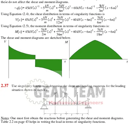
Using the information in Table 2.2 on page 43, the load distribution can be written in terms of singularity functions. Here we decide to ignore the terms acting at the right end of the beam, since these do not affect the shear and moment diagrams.

q x

( )=

45kN x −1−5kN

Using Equation (2.4), the shear distribution in terms of singularity functions is V x

( )

=45kN x 0−5kN

Using Equation (2.5), the moment distribution in terms of singularity functions is: M x

( )

=45kN x 1−5kN

The shear and moment diagrams are sketched below.

2.37

Use singularity functions to determine the shear and bending moments for the loading situation shown in sketch z.

Notes: One must first obtain the reactions before generating the shear and moment diagrams. Table 2.2 on page 43 helps in writing the load in terms of singularity functions.

Solution:

Moment equilibrium about point A gives: MA=0=2Pl+ Therefore, the load distribution is given by

(34)

Note that we have ignored the terms which become active at x=4l, since these do not affect the diagram or calculations on the beam. The shear distribution is obtained from Equation (2.4) as:

V x

( )

= 3w0l

Using Equation (2.5), the moment distribution in terms of singularity functions is:

M x

( )

= 3w0l

2.38

Obtain the shear force and moment expressions using singularity functions for a pinned beam at both ends with loading conditions described in sketch aa. Draw a free-body diagram of the forces acting on the bar. Draw the shear force and moment along the length of the bar and give tabular results. Assume w0=4kN/m, P=3kN, and l=12m.

Notes: One must first obtain the reactions before generating the shear and moment diagrams. Table 2.2 on page 43 helps in writing the load in terms of singularity functions.

Solution:

Moment equilibrium about point A gives: MA=0=P Therefore, the load distribution is given by

q x( )= Ay x−1−3w0

Note that we have ignored the terms which become active at x=l, since these do not affect the diagram or calculations on the beam. The shear distribution is obtained from Equation (2.4) as:

V x( )= Ay x 0−3w0 Using Equation (2.5), the moment distribution in terms of singularity functions is:

(35)

2.39

A steel bar is loaded by a tensile force P=25kN. The cross section of the bar is circular with a radius of 7mm. What is the normal stress in the bar?

Notes: Equation (2.7) is needed to solve this problem. Solution:

The cross sectional area of the bar is:

A= πr2 = π

(

0.007m

)

2 =1.539×10⁻⁴m2 Equation (2.7) gives

σ =P A=

25kN

1.539×10⁻⁴m2 =162MPa

2.40

A stainless steel bar of square cross section has a tensile force of P=15kN acting on it. Calculate how large the side l of the cross-sectional area must be to give a tensile stress in the bar of 120MPa.

Notes: Equation (2.7) is needed to solve this problem. Solution:

The cross sectional area of the bar is l2. Therefore, from Equation (2.7), σ =P

A; A=l

2= P σ; l=

P σ =

15kN

120MPa =0.0112m=11.2mm

2.41

What is the maximum length lmax that a copper wire can have if its weight should not give a higher stress than 75 MPa when it is hanging vertically? The density of copper is 8900 kg/m3, and the density of air is so small relative to that of copper that it may be neglected. The acceleration of gravity is 9.81 m/s2.

Notes: Equation (2.7) is needed to solve this problem. Solution:

If the wire has a cross sectional area of A, then its volume is V=Almax. The weight of this wire is P=ρgAlmax

(36)

σ = P A= ρ

gAlmax

A = ρglmax; lmax = σρg =

75MPa 8900kg/m3

(

)

(

9.81m/s2

)

=859m

2.42

A machine weighing 5 tons will be lifted by a steel rod with an ultimate tensile strength of 860 MPa. A safety factor of 5 is to be used. Determine the diameter needed for the steel rod.

Notes: Equations (1.1) and (2.7) are needed to solve this problem. Note that a ton is 1000 kg when the problem is stated in metric units.

Solution:

The design stress is determined from Equation (1.1) as: ns = σσall

d

; σd = σall

ns =

860MPa

5 =172MPa

The applied load is P=(5000kg)(9.81m/s2)=49.05kN. Therefore, the required diameter is calculated from Equation (2.7) as:

σ = P A=

P πd2

4       

; d= 4P πσ =

4 49.05kN

(

)

π

(

172MPa

)

=0.0191m=19.1mm

2.43

The largest measured ocean depth (near the Philippines in the Pacific) is 11 km. What ultimate strength is required for a steel wire to reach the bottom without being torn apart by its own weight? The density of steel is 7860kg/m3 and that of water is 1000kg/m3. Notes: The approach is very similar to problem 2.41, but now the buoyancy force is subtracted from the load.

Solution:

If the wire has a cross sectional area of A, then its volume is V=Almax. The load on the top of the wire is the weight of the wire minus the buoyancy force which tends to support the wire. Therefore,

P=(ρsteel-ρwater)gAlmax From Equation (2.7),

σ = P A=

ρsteel− ρwater

(

)

gAlmax

A = ρ

(

steel− ρwater

)

glmax

=

(

7860kg/m3−1000kg/m3

)

(

9.81m/s2

)

(

11000m

)

=740MPa

Reviewing the properties of steel on the inside front cover, there is no steel that can reach to this depth without failing at the surface.

(37)

Notes: It is very helpful to complete Problem 2.43 before attempting this problem. This is an open-ended problem, with many possible solutions. Students should be encouraged to develop their own creative solutions to this problem.

Solution:

The obvious solution is to make the wire of a polymer or other material with exactly the same density as water and with the same compressibility as water. Each part of the wire is then buoyant and the tensile stress is zero along the whole wire. Another way is to use a steel wire but attach floats at regular intervals, this producing buoyancy of the wire parts.

2.45

A string on a guitar is made of nylon and has a cross-sectional diameter of 0.6mm. It is tightened to a force P=15N. What is the stress in the string?

Notes: Equation (2.7) is needed to solve this problem. Solution:

The cross sectional area of the string is: A= πd

2

4 = π

0.0006m

(

)

2

4 =2.827×10

−7m2

Equation (2.7) gives

σ =P A=

15N

2.827×10⁻⁷m2 =53.1MPa

2.46

Determine the normal and shear stresses in sections A and B of sketch bb. The cross-sectional area of the rod is 0.025m2. Ignore bending and torsional effects.

Notes: To solve this problem, one must be capable of solving for the reactions at A, be familiar with the method of sections, and be able to use Equation (2.7).

Solution:

From equilibrium, the reactions at the wall include the forces Rx=0, Ry=10kNcos30°=8.66kN, and Rz=10kNsin10°=5kN. Taking a section at A, and applying Equation (2.7),

σ = −Py

A = −

8.66kN

0.025m2 = −346.4kPa

The maximum shear stress is discussed in Chapter 5, but we can estimate the average shear stress as

τave =

Pz

A = − 5.0kN

(38)

The negative signs are consistent with the sign convention shown on page 33. At location B, there is no normal force, so σ=0. Since we are told to ignore torsional effects, we can estimate the average shear stress as:

τave =

P A=

10kN

0.025m2 =400kPa

2.47

Determine the normal and shear stresses due to axial and shear forces at sections A and B in sketch cc. The cross sectional area of the rod is 0.025m2.

Notes: To solve this problem, one must be capable of solving for the reactions at A, be familiar with the method of sections, and be able to use Equation (2.7). Also, use θ=30°. Finally, calculate the average shear stress, not the maximum for a round cross section as is discussed in Chapter 4. Solution:

Taking a section at AA, there is an axial force and a shear force. While one can work in the x and y directions, the answer is more easily obtained by applying equilibrium to the coordinate system which is defined by the section. The free body diagram of the forces (moments are ignored for this problem) at section AA are:

Therefore, taking force equilibrium in the direction normal to the surface:

Σ

F=0=Pn-Psinθ; Pn=Psinθ=(10kN)(sin30°)=5kN Therefore the normal stress is:

σ = Pn

A = 5kN

0.025m2 =200kPa Taking force equilibrium in the direction of the surface yields:

Σ

F=0=Ps-Pcosθ; Ps=Pcosθ=(10kN)(cos30°)=8.66kN Therefore the average shear stress is

τ = Ps

A =

8.66kN

(39)

At section BB, force equilibrium gives Pn=0 and Ps=10kN. Therefore the normal stress is σ=0 and the shear stress is

τ = Ps

A = 10kN

0.025 m2 =400kPa

2.48

For the stress element given in Figure 2.13 determine how large the shear stress will become if all three normal stresses are doubled.

Notes: This problem is deceptively simple. Solution:

The normal stresses and shear stresses are independent of each other; if the normal stresses are doubled, there is no effect on the shear stresses, so they remain the same.

2.49

The normal stresses in the x, y, and z directions are all equal to 100MPa, and the shear stresses are all zero. Find the stresses acting on a plane having the normal in the direction of the space diagonal

1 3,

1 3,

1 3 

 

   .

Notes: This problem uses Equations (B.4) through (B.9). Solution:

Refer to the directions in the new plane as x’, etc. These stresses are given by Equations (B.4) through (B.9) in Appendix B. As long as the directions are orthogonal,

σx =1

3

(

σx+ σy+ σz

)

+0+0+0=100MPa σy = 1

3

(

σx+ σy+ σz

)

+0+0+0=100MPa σz =1

3

(

σx+ σy+ σz

)

+0+0+0=100MPa The shear stresses are:

τz ,x = σ

3

[

cos

(

x ,z

)

+cos

(

x ,x

)

+cos

(

x ,y

)

]

+0+0+0 If x’ is perpendicular to y’ and z’, then this gives τz’,x’=0. Similarly, τx’,y’=τy’,z’=0.

2.50

If the stresses are such that σx=-σy and σz=τxy=τxz=τyz=0, find the shear stress acting on the plane diagonal between the x and y axes and parallel to the z direction.

Notes: Equation (B.8) solves this problem. Solution:

(40)

cos

(

x ,x

)

= 1

2, c o s

(

x ,y

)

= 1

2, c o s

(

x ′ ,z

)

=0 cos

( )

y ′ ,x = − 1

2 , c o s

( )

y ,y = 1

2, c o s

( )

y ,z =0 cos

( )

z ,x =0 , c o s

( )

z ,y =0, cos

( )

z ,z =1

Using Equation (B.8) on page 906 yields the following, keeping only non-zero terms: τx y = σx

2 − 1

2   

   +

σy 2

1 2   

  +0+0+0+0= − σ2x + σy

2 Since σx=-σy, one can write that τx’y’=-σx=σy.

2.51

A stressed element with shear stress τyx acting in the x-direction on the surface has the normal in the y direction. Determine the shear stress acting in the y direction on the surface having a normal in the x direction.

Notes: This merely requires an understanding of equilibrium. Solution:

Refer to Figure 2.14 (b) to visualize the stresses. Applying moment equilibrium about the z-axes yields:

M=0=

τxydA1 dx

2

( )

2 − τyxdA2 dy

2

( )

2 Since dA1=dydz and dA2=dxdz,

τxydxdydz− τyxdxdydz=0 ; τxy= τyx

2.52

Sketch dd shows a distributed load on a semi-infinite plane. The stress in polar coordinates based on the plane stress assumption is

σr = −2w0πcosθ

r σθ=τrθ=τθr=0

Determine the expressions σx, σy, and τxy in terms of r and θ.

Notes: Since x,y and r,θ are orthogonal coordinates, Equations (2.12) and (2.14) can be used to solve the problem.

Solution:

The derivation on pages 51 and 52 applies equally well if the desired stress in Equation (2.12) is σx in terms of σr, σθ, and τrθ. Therefore,

σx =2τrθsinθcosθ + σrcos2θ +σθsin2θ =0−

2w0cosθ πr   

  cos2θ +0= −

Gambar

Table 2.2 on page 43 helps in writing the load in terms of singularity functions.
Table 4.1 gives the moment of inertia about the circle’s centroid as:
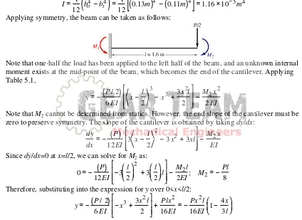
Table 5.1, = − (P/ 2)� �
+7

Referensi

Dokumen terkait

4.4 Overall Equipment Effectiveness Rate The calculation value of OEE rate can use equation 4 to identify the effectiveness of a manufacturing machine or generally can be used

10 From the novel, it can be seen that Jane Austen tries to reveal her feeling that woman should be independent and does not depend on man?. That woman can stand alone but

To solve the problems in writing procedure text, English teacher should be able to choose the suitable media to present the lesson to the students. The writer chooses video

There are many techniques that can be used to help students generate their ideas and gather details for their procedure, but in this case the writer chooses

1.5.1 Theoretical Uses : This research is expected to be a reference for other researchers and readers who focus their research on the topic related to male and female

Solving Telegraph Equations Using Aboodh Transform Aboodh transform can be used to solve the differential equation of telegraph in an efficient manner, to prove the capability of this

This simple equation demonstrates that the fringe shift in radians quantified by an interferometer when measuring a folding, binding, or hybridization event in free-solution no labels

Cookies are included in the type of pastries which does not require high protein so that lotus root flour can be used for replacing wheat flour as an alternative basic ingredient in