1
CHAPTER 1 INTRODUCTION
1.1 Background of Study
Racket is a sports implement consisting of a handled frame with an open hoop across which a network of cord is stretched tightly. It is used for striking a ball in such games as squash, tennis, racquetball, and badminton. Collectively, these games are known as racket sports. The frame of racket for all sports was traditionally made of laminated wood and the strings of animal intestine known as gut. The traditional racket size was limited by the strength and weight of the wooden frame which had to be strong enough to hold the strings and stiff enough to hit the ball or shuttle. Manufacturers started adding non-wood laminates to wood racquets to improve stiffness. Non-wood racquets were made first of steel, then of aluminium, and then carbon fiber composites. Wood is still used for real tennis, racquets, and xare. Most rackets are now made of composite materials including carbon fibre, glassfibre, metals such as titanium alloys or ceramics.
Gut has partially been replaced by synthetic materials including nylon, polyamide, and other polymers. Rackets is restrung when necessary, which may be after every match for a professional or never for a social player.
2 1.2 Problem Statement
A common strategy in squash is to hit the ball straight up the side walls to the back corners referred to as a "rail," straight drive, wall, or "length", then move to the centre of the court near the "T" to be well placed to retrieve the opponent's return. Attacking with soft or "short" shots to the front corners (referred to as "drop shots") causes the opponent to cover more of the court and may result in an outright winner. This strategy normally has been applied for all squash player. Rallies between experienced players may involve 30 or more shots and therefore a very high premium is placed on squash racket. During the game, most of player using strategy with is using the difficulty hitting ball when the ball near the wall. So this will make the racket offense hitting wall. When hitting the wall, the frame racket will be damage and also reduce the strength of the squash racket.
This is because of the impact between the racket and the wall when the strategy is applied. Stress concentration in the racket will then determine its vulnerable points for failure. Many rackets such as squash rackets will be manufacture of rackets by injection molding of fiber-reinforced thermoplastic resins. Each of these types of rackets includes a head formed of a generally oval frame with strings supported thereon, a handle, and a throat that provides a transition between the handle and the head. The size and weight of the racket is tailored to the specific racket sport and the characteristics of the player. In recent years, considerable effort has been devoted to improving both designs of the rackets and the materials of construction. Designs have been changed to increase the area of the racket head where the most satisfactory impact is achieved, the "sweet spot".
Racket frames were traditionally made of wood or metal. More recently, fiber- reinforced composite materials have been used to form the frames of advanced rackets, providing improved strength and durability Racket sports pose the challenge of combining physical agility, ball, racket and eye coordination, tactical analysis and physical and psychological endurance. Because of these combinations they are challenging to both sports. Therefore, this project will aim to design and simulation of the racket to get the perfect condition and to get the improvement in its impact strength.
3 1.3 Objective And Scope of Study
The main objectives of this research are:
To conduct a Finite Element Analysis of the squash racket
To establish the sites of stress can contraction and stress concentration factor
To predict the possible failure mode
The scope of work for this project is to investigate the design and workability of squash racket. This project is to understand in selecting a squash racquet is how they differ.
There some of the main characteristics of squash racquets; and on how those characteristics affect how the racquet will play and their performance. Understand, though, that there is no consensus on these playing parameters. Also the scope of work for this project is to do analysis of the squash racket. For this project, ANSYS will go to be use to do the analysis to determine the stress concentration and also stress concentration factor for the squash racket. With the result of the stress concentration and stress concentration factor will determine and improve its impact strength of the squash racket. Also with this can predict the possible failure mode and identify the optimum design for the squash racket.
4
CHAPTER 2
LITERATURE REVIEW
2.1 Finite Element Analysis
FEA consists of a computer model of a material or design that is stressed and analyzed for specific results. Also known as Finite Element Method. It is used in new product design, and existing product refinement. With this analysis, is able to verify a proposed design will be able to perform prior to manufacturing or construction. Modifying an existing product or structure is utilized to qualify the product or structure for a new service condition. In case of structural failure, FEA may be used to help determine the design modifications to meet the new condition. Within each of these modeling schemes, the programmer can insert numerous algorithms (functions) which may make the system behave linearly or non-linearly. Linear systems are far less complex and generally do not take into account plastic deformation. Non-linear systems do account for plastic deformation, and many also are capable of testing a material all the way to fracture. A variety of specializations under the umbrella of the mechanical engineering discipline (such as aeronautical, biomechanical, and automotive industries) commonly use integrated FEA in design and development of their products. In a structural simulation, FEA helps tremendously in producing stiffness and strength visualizations and also in minimizing weight, materials, and costs. FEA allows detailed visualization of where structures bend or twist, and indicates the distribution of stresses and displacements. FEA software provides a wide range of simulation options for controlling the complexity of both modeling and analysis of a system. Similarly, the desired level of accuracy required and associated computational time requirements can be managed simultaneously to address most engineering applications. FEA allows entire designs to be constructed, refined, and optimized before the design is manufactured.
This powerful design tool has significantly improved both the standard of engineering
5
designs and the methodology of the design process in many industrial applications. The introduction of FEA has substantially decreased the time to take products from concept to the production line. It is primarily through improved initial prototype designs using FEA that testing and development have been accelerated. In summary, benefits of FEA include increased accuracy, enhanced design and better insight into critical design parameters, virtual prototyping, fewer hardware prototypes, a faster and less expensive design cycle, increased productivity, and increased revenue.
2.2 ANSYS
ANSYS, Inc. is an engineering simulation software provider. It develops general- purpose finite element analysis and computational fluid dynamics software. While ANSYS has developed a range of computer-aided engineering (CAE) products, it is perhaps best known for its ANSYS Mechanical and ANSYS Multiphysics products.
ANSYS Mechanical and ANSYS Multiphysics software are non exportable analysis tools incorporating pre-processing (geometry creation, meshing), solver and post- processing modules in a graphical user interface. These are general-purpose finite element modeling packages for numerically solving mechanical problems, including static/dynamic structural analysis (both linear and non-linear), heat transfer and fluid problems, as well as acoustic and electro-magnetic problems. ANSYS Mechanical technology incorporates both structural and material non-linearities. ANSYS Multiphysics software includes solvers for thermal, structural, CFD, electromagnetics, and acoustics and can sometimes couple these separate physics together in order to address multidisciplinary applications. ANSYS software can also be used in Civil Engineering, Electrical Engineering, Physics and Chemistry. ANSYS, Inc. acquired the CFX computational fluid dynamics code in 2003 and Fluent, Inc. in 2006. The CFD packages from ANSYS are used for engineering simulations.
6 2.3 CATIA
CATIA (Computer Aided Three Dimensional Interactive Application) is a multi- platform CAD/CAM/CAE commercial software suite developed by French company Dassault Systemes and marketed world-wide by IBM. Written in the C++ programming language, CATIA is the cornerstone of the Dassault Systemes PLM software suite. The software was created in the late 1970s and early 1980s to develop Dassault's Mirage fighter jet, but was subsequently adopted in the aerospace, automotive, shipbuilding, and other industries. Commonly referred to as 3D Product Lifecycle Management software suite, CATIA supports multiple stages of product development (X). The stages range from conceptualization, through design (CAD) and manufacturing (CAM), until analysis (CAE). CATIA is widely used throughout the engineering industry, especially in the automotive and aerospace sectors.
2.4 Force
In physics, a force is that which can cause an object with mass to change its velocity.
Force has both magnitude and direction, making it a vector quantity. Newton's second law states that an object with a constant mass will accelerate in proportion to the net force acting upon and in inverse proportion to its mass. Equivalently, the net force on an object equals the rate at which its momentum changes.
Forces acting on three-dimensional objects may also cause them to rotate or deform, or result in a change in pressure or even change volume in some cases. The tendency of a force to cause changes in rotational speed about an axis is called torque. Deformation and pressure are the result of stress forces within an object.
7 2.4.1 The Impulse-Momentum Theorem 2.4.1.1 Newton's second law
Newton's second law can be written as a vector differential equation:
where F is the force vector, m is the mass of the body, v is the velocity vector and t is time.
It should be noted that, as is consistent with the law of inertia, the time derivative of the momentum is non-zero when the momentum changes direction, even if there is no change in its magnitude. See time derivative.
Since the mass of the system is constant, this differential equation can be rewritten in its simpler and more familiar form:
where
is the acceleration.
2.4.1.2 Impulse
The impulse of the force is the product of the average force and the time interval during which the force acts. Impulse is a vector quantity and has the same direction as the average force.
where
F is the constant total net force applied,
Δt is the time interval over which the force is applied,
8 m is the constant mass of the object,
Δv is the change in velocity produced by the force in the considered time interval, and mΔv = Δ(mv) is the change in linear momentum,
p is momentum.
2.4.1.3 Momentum
The linear momentum of an object is the product of the object’s mass m and velocity v.
Linear momentum is a vector quantity that point in the same direction as the velocity.
where P is the momentum, m is the mass and v is the velocity.
2.4.1.4 Impulse – Momentum Theorem
When a net force acts on an object, the impulse of this force is equal to the change in momentum of the object.
where
F is the constant total net force applied,
t is the time interval over which the force is applied, m is the constant mass of the object,
v1 is the final velocity of the object at the end of the time interval, and v0 is the initial velocity of the object when the time interval begins.
9 2.5 Stress Concentration
A stress concentration (often called stress raisers or stress risers) is a location in an object where stress is concentrated. An object is strongest when force is evenly distributed over its area, so a reduction in area, e.g. caused by a crack, results in a localized increase in stress. A material can fail, via a propagating crack, when a concentrated stress exceeds the material's theoretical cohesive strength. The real fracture strength of a material is always lower than the theoretical value because most materials contain small cracks that concentrate stress. The fracture of a material is dependent upon the forces that exist between the atoms. Because of the forces that exist between the atoms, there is a theoretical strength that is typically estimated to be one-tenth of the elastic modulus of the material. However, the experimentally measured fracture strengths of materials are found to be 10 to 1000 times below this theoretical value. The discrepancy is explained to exist because of the presence of small flaws or cracks found either on the surface or within the material. These flaws cause the stress surrounding the flaw to be amplified where the magnification is dependent upon the orientation and geometry of the flaw. The stress is concentrated around the crack tip or flaw developing the concept of stress concentration. Stress raisers are defined as the flaws having the ability to amplify an applied stress in the locale.
2.5.1 Causes
Geometric discontinuities cause an object to experience a local increase in the intensity of a stress field. The examples of shapes that cause these concentrations are: cracks, sharp corners, holes and, changes in the cross-sectional area of the object. High local stresses can cause the object to fail more quickly than if it wasn't there.
10 2.5.2 Prevention
A counter-intuitive method of reducing one of the worst types of stress concentrations, a crack, is to drill a large hole at the end of the crack. The drilled hole, with its relatively large diameter, causes a smaller stress concentration than the sharp end of a crack. This is however, a temporary solution that must be corrected at the first opportune time. It is important to systematically check for possible stress concentrations caused by cracks -- there is a critical crack length of 2a (half the length of the crack) for which, when this value is exceeded, the crack proceeds to definite catastrophic failure. This ultimate failure is definite since the crack will propagate on its own once the length is greater than 2a. (There is no additional energy required to increase the crack length so the crack will continue to enlarge until the material fails.) The origins of the value 2a can be understood through Griffith's theory of brittle fracture.
2.5.3 Stress concentration factor
A stress concentration factor is a ratio of the greatest stress (σmax) in the area of a notch or other stress raiser to the corresponding nominal stress or reference stress (σ) of the gross cross-section. It is a theoretical indication of the effect of stress concentrators on mechanical behavior. The maximum stress felt near a crack occurs in the area of lowest radius of curvature. In an elliptical crack of length 2a and width 2b, under an applied external stress σ, the stress at the ends of the major axes is given by:
Equation 1: A stress concentration factor
where ρ is the radius of curvature of the crack tip. As the radius of curvature approaches zero, the maximum stress approaches infinity. Note that the stress concentration factor is a function of the geometry of a crack, and not of its size. These factors can be found in
11
typical engineering reference materials to predict the stresses that could otherwise not be analyzed using strength of materials approaches.
2.5.4 Concentration factor calculation
By using the finite element method, this concentration factor will be determined. There are another ways to calculate the stress concentration factor which using the Equation 1.
When using the finite element method, value will more accurate. This is because the program is more sensitive in division of elements. In other words, the difference is probably due to the ability of element analysis of program.
2.6 Von-Mises Stress
Von Mises Stress is actually a misnomer. It refers to a theory called the "Von Mises - Hencky criterion for ductile failure". In an elastic body that is subject to a system of loads in 3 dimensions, a complex 3 dimensional system of stresses is developed (as you might imagine). That is, at any point within the body there are stresses acting in different directions, and the direction and magnitude of stresses changes from point to point. The Von Mises criterion is a formula for calculating whether the stress combination at a given point will cause failure.
There are three "Principal Stresses" that can be calculated at any point, acting in the x, y, and z directions. (The x,y, and z directions are the "principal axes" for the point and their orientation changes from point to point, but that is a technical issue.)
Von Mises found that, even though none of the principal stresses exceeds the yield stress of the material, it is possible for yielding to result from the combination of stresses. The Von Mises criteria is a formula for combining these 3 stresses into an equivalent stress, which is then compared to the yield stress of the material. (The yield stress is a known property of the material, and is usually considered to be the failure stress.) The equivalent stress is often called the "Von Mises Stress" as a shorthand description. It is not really a stress, but a number that is used as an index. If the "Von
12
Mises Stress" exceeds the yield stress, then the material is considered to be at the failure condition.
In material science and engineering the von Mises yield criterion can be also formulated in terms of the von Mises stress or equivalent tensile stress, a scalar stress value that can be computed from the stress tensor. In this case, a material is said to start yielding when its von Mises stress reaches a critical value known as the yield strength. The von Mises stress is used to predict yielding of materials under any loading condition from results of simple uniaxial tensile tests. The von Mises stress satisfies the property that two stress states with equal distortion energy have equal von Mises stress.
2.7 Aluminium Alloys
Aluminium alloys are alloys of aluminium, often with copper, zinc, manganese, silicon, or magnesum. They are much lighter and more corrosion resistant than plain carbon steel, but not as corrosion resistant as pure aluminium. Bare aluminium alloy surfaces will keep their apparent shine in a dry environment due to the formation of a clear, protective oxide layer. Galvanic corrosion can be rapid when aluminium alloy is placed in electrical contact with stainless steel, or other metals with a more negative corrosion potential than the aluminium alloy, in a wet environment. Aluminium alloy and stainless steel parts should only be used together in water-containing systems or outdoor installations if provision is made for either electrical or electrolytic isolation between the two metals.
Aluminium alloy compositions are registered with the Aluminium Association. Many organizations publish more specific standards for the manufacture of aluminium alloy, including the Society of Automotive Engineers standards organization, specifically its aerospace standards subgroups, and the ASTM
13
Aluminium alloys with a wide range of properties are used in engineering structures.
Alloy systems are classified by a number system (ANSI) or by names indicating their main alloying constituents (DIN and ISO). Selecting the right alloy for a given application entails considerations of strength, ductility, formability, weld-ability and corrosion resistance to name a few. A brief historical overview of alloys and manufacturing technologies is given in Ref. Aluminium is used extensively in modern aircraft due to its high strength to weight ratio.
2.7.1 Flexibility
Improper use of aluminium may result in problems, particularly in contrast to iron or steel, which appear "better behaved" to the intuitive designer, mechanic, or technician.
The reduction by two thirds of the weight of an aluminium part compared with a similarly sized iron or steel part seems enormously attractive, but it must be noted that this replacement is accompanied by a reduction by two thirds in the stiffness of the part.
Therefore, although direct replacement of an iron or steel part with a duplicate made from aluminium may still give acceptable strength to withstand peak loads, the increased flexibility will cause three times more deflection in the part. The strength and durability of aluminium varies widely, not only as a result of the components of the specific alloy, but also as a result of the manufacturing process. Where failure is not an issue but excessive flex is undesirable due to requirements for precision of location, or efficiency of transmission of power, simple replacement of steel tubing with similarly sized aluminium tubing will result in a degree of flex which is undesirable; for instance, the increased flex under operating loads.
14 2.7.2 Heat Sensitivity
Stresses in overheated aluminium can be relieved by heat-treating the parts in an oven and gradually cooling it in effect annealing the stresses. Yet these parts may still become distorted, so that heat-treating caused, can result in a significant fraction becoming misaligned. If the misalignment is not too severe, the cooled parts may be bent into alignment. If is properly designed for rigidity, that bending will require enormous force.
Aluminium's intolerance to high temperatures, the extremely high thermal conductivity of aluminium prevented the throat from reaching the melting point even under massive heat flux, resulting in a reliable lightweight component.
15
CHAPTER 3 METHODOLOGY
3.1 Project Flow
As shown in Figure 3.1, all information and data which are related to the studies have been gathered. All findings are basically on the of racket. Several parameters and different type, condition of racket have been prepared to investigate the stress characteristic in a racket. Then, the shape identification and image of the flame based on the condition to be investigated. The results will be recorded and comparison will be made here as a conclusion, and also any recommendation.
Flow Chart
Figure 3.1: Project flow planning Information and data gathering
Design of the racket using Catia®
Finite Element Analysis using Ansys®
Evaluation of analysis
Conclusion and Recommendation
Method and Procedure Planning
16 3.2 Gantt Chart
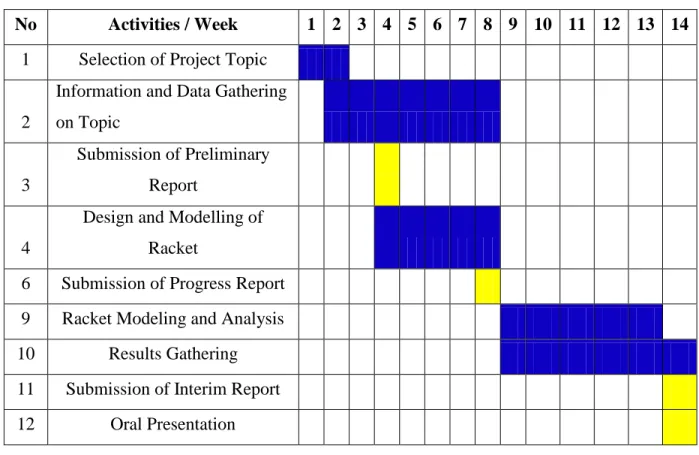
Table 3.1: The Gantt chart for Semester 1
No Activities / Week 1 2 3 4 5 6 7 8 9 10 11 12 13 14 1 Selection of Project Topic 2
Information and Data Gathering
on Topic
3
Submission of Preliminary
Report
4
Design and Modelling of
Racket
6 Submission of Progress Report 9 Racket Modeling and Analysis 10 Results Gathering 11 Submission of Interim Report 12 Oral Presentation
Process Milestone
Based on the table 1, semester 1 is about doing a lot of research in order to gain deep knowledge in designation and characteristic of squash racket. During semester 1, the designing and identifying process will be handled in this semester. The data collection will also handled in this semester.
17
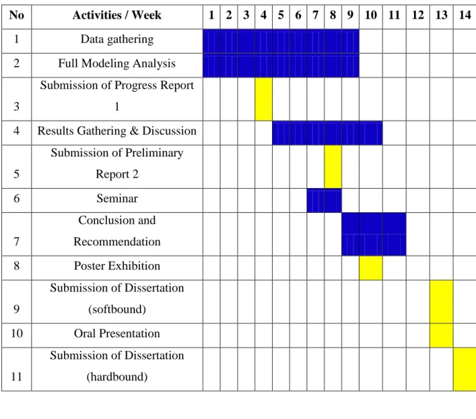
Table 3.2: The Gantt chart for Semester 2
No Activities / Week 1 2 3 4 5 6 7 8 9 10 11 12 13 14
1 Data gathering
2 Full Modeling Analysis 3
Submission of Progress Report
1
4 Results Gathering & Discussion 5
Submission of Preliminary
Report 2
6 Seminar
7
Conclusion and
Recommendation 8 Poster Exhibition 9
Submission of Dissertation
(softbound) 10 Oral Presentation 11
Submission of Dissertation
(hardbound)
Process Milestone
Based on the Table 3.2, semester 2 is about doing a lot of research and analysis in order to gain deep knowledge in design and it’s characteristic to improve the impact strength for the squash racket by find the stress concentration. During semester 2, experiment procedure will be clearly prepared due to modeling and design for the racket squash.
Also some doing research and study the case study that have been done during doing the finite element analysis. It is about the experiment testing and data collection.
18 3.3 Project Idenfication
In order to have the better design, a lot of stages need to be done because it deals with the physical principles, the proper functioning and the production of mechanical systems. This means mechanical design is very important in order to produce the best design and the fabrication process. The starting point is good mechanical design and the role of materials. It starts with a market need or new idea and it ends with full specifications of a product that fill the needs of the idea.
3.4 Material Idenfication
In order to choose the material to designation and analysis of squash racket frame, some of the criteria need to meet the requirement. The requirement needed to ensure the best design of the frame racket was the strength of the material to sustain the heat and the weight of the material. The strength of the material needed to be strong, can sustain the heat and the availability.
3.5 Project Requirement
For the designation for squash racket, software CATIA will be use to create the previous design that have been in the market. There are characteristic for the designation of the racket:
Weight of the racket - The weight of the racquet is its most obvious characteristic, and the weights are quite variable. Heavier racquets are less maneuverable but more powerful and more stable than the lighter counterpart.
Balance - Rackets with the same weight could have different balance. A racket with more weight distributed on the head rather than the handle is called a head heavy racquet, and the opposite is called a head light racquet. Head heavy rackets give players more power but lack maneuverability because of weight distribution. On the other hand, head light racquets provide more control and maneuverability.
19
Flex - The flex or stiffness of a racket is the racket’s resistance to bending or deforming upon impact with the ball. A stiffer racquet bends less, thus depleting less energy from the ball and offers more power. A flexible racket bends more, resulting in more energy loss and less power, but more control of the ball.
Players with short swing would want to have stiffer rackets since it will give the most power. A much less stiff racket give less power and would suit players with longer swing who can generate their own power. Stiff rackets also offer solid feel while less stiff racquets have a softer feel.
Shape of the racket head - Racket manufacturers experiment with different racket heads and market the results of their experimentation. In general, larger racket heads give you a greater margin for error and also additional power.
Certain racket throat designs make for decreased racquet durability.
3.6 Project Designation
The first process of the project is to design the squash racket using Catia® software.
After all the design process has been done, the squash racket frame has been design. The design and the dimension have been finalized. The geometrical designs have been used due the current squash racket frame in market. The design will help author in better understanding on characteristic and effect of attachments on improving and optimized the impact of this frame’s racket.
3.7 Squash Racket Modeling
As the first step for this project, it is required to model the squash racket before continue with the computerized finite element analysis using ANSYS® software. To model the racket, CAD simulation software, namely CATIA® V5 is required to model the squash racket frame. The reason of not modeling the racket by using ANSYS® software is due to the complex design of the racket itself such as the angularity of the vanes and splitter.
As being recommended, the CATIA® V5 has the future of abilities to be imported or integrated with ANSYS® software. Modeling of the racket takes time because it is need a good practices and efforts to learn.
20 3.8 Force Idenfication
When the frame racket being hit the wall, force applied to the frame racket squash by the wall changes during the time of contact. The magnitude of the force is zero at the instant t0 just before the racket touches the wall. During contact, the force rises to a maximum and then returns to zero at the time tf when the racket leaves the wall. The impulse of a force and the linear momentum of an object will describe how to a time- varying a force affects the motion of the squash racket and the wall. This impulse and momentum will be used with Newton’s Second Law of motion to produce The Impulse- Momentum Theorem.
During the collision of frame squash racket and wall, it is often difficult to measure the net force, so its not easy to determine the impulse directly. On the other hand, it is usually straightforward to measure the mass and velocity of the squash racket and wall, so that its momentum just after the collision and mv0 just before the collision can be found. Thus, the impulse – momentum theorem allows gaining information about impulse indirectly by measuring the change in momentum that the impulse causes.
3.9 Finite Element Analysis
Finite Element Analysis will be done by using the ASNYS software to determine the stress concentration and stress concentration factor. It will also predict the failure mode for the rackets. FEA uses a complex system of points called nodes which make a grid called a mesh. This mesh is programmed to contain the material and structural properties which define how the structure will react to certain loading conditions. Nodes are assigned at a certain density throughout the material depending on the anticipated stress levels of a particular area. Regions which will receive large amounts of stress usually have a higher node density than those which experience little or no stress. Points of interest may consist of: fracture point of previously tested material, fillets, corners, complex detail, and high stress areas.
21 3.9.1 Building the Model
The FEA modeling process requires three types of input data: geometry, material properties, and loading.
3.9.1.1 Geometry
For the squash racket frame, "geometry" means the overall frame dimensions (such as racket lengths, intersection points, and angles). For the geometry process, it will export data from the modeling using the Catia® software.
3.9.1.2 Material Properties
The material properties needed for setting up the model include elastic modulus, shear modulus, Poisson ratio, and mass density.
3.9.1.3 Loading
Finally, the externally acting loads must be specified in terms of magnitude, direction, and point of application on the frame. Loading information is derived from experiment, analytical deduction, and government standards. This information is then used to specify forces and moments acting at endpoints (nodes) of key elements. Correct loading information is absolutely vital in producing reliable results. In this study, a major effort was made to define a realistic and self-consistent set of load conditions.
22 3.9.2 Meshing
This mesh is programmed to contain the material and structural properties which define how the structure will react to certain loading conditions. Nodes are assigned at a certain density throughout the material depending on the anticipated stress levels of a particular area. Regions which will receive large amounts of stress usually have a higher node density than those which experience little or no stress. Points of interest may consist of:
fracture point of previously tested material, fillets, corners, complex detail, and high stress areas. The mesh acts like a spider web in that from each node, there extends a mesh element to each of the adjacent nodes. This web of vectors is what carries the material properties to the object, creating many elements.
3.9.3 FEA Solution and Output Data
Once the input data for the FE model has been specified, the computer then solves a set of simultaneous linear equations for node displacements and internal element forces.
The finite-element analysis can easily calculate the element stresses for virtually any specified load condition.
23
CHAPTER 4
RESULT AND DISCUSSION
This is chapter gives the explanation on the theoretical, requirements and limitations of the material and finite element project for the squash racket
4.1 Material Idenfication
For this project, the material for the existing squash racket is aluminium alloy.
Aluminium alloys are alloys of aluminium, often with copper, zinc, manganese, silicon, or magnesum. They are much lighter and more corrosion resistant than plain carbon steel, but not as corrosion resistant as pure aluminium. The table 4.1 show the material properties for the aluminium alloy that be used in this project.
Table 4.1: Aluminium Alloy Properties
Young Modulus 71000000000 Pa
Poisson’s Ratio 0.33
Density 2770 kg/m3
Thermal Expansion 0.000023 1/0C
Tensile Yield Strength 280000000 Pa
Compression Yield Strength 280000000 Pa
Tensile Ultimate Strength 310000000 Pa
24 4.1.1 Flexibility
Aluminium alloys have a part compared with a similarly sized iron or steel part seems enormously attractive, but there is a reduction by two thirds in the stiffness of the part.
Aluminium alloys give acceptable strength to withstand peak loads, also the increased flexibility will cause three times more deflection in the part. By using aluminium alloys, failure is not an issue but excessive flex is undesirable due to requirement for precision location, or effiency of transmission of power will result in a degree of flex which is undesirable; the increased flex under operating loads.
4.1.2 Heat Sensitivity
Aluminium's intolerance to high temperatures, the extremely high thermal conductivity of aluminium prevented the throat from reaching the melting point even under massive heat flux, resulting in a reliable lightweight component. Stresses in overheated aluminium can be relieved by heat-treating the parts in an oven and gradually cooling it in effect annealing the stresses.
25 4.2 Design and Modeling
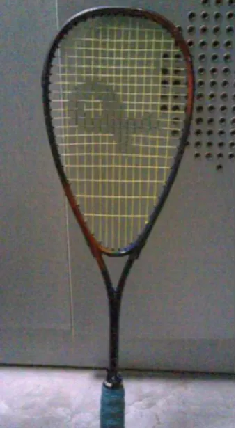
The dimension and geometry of the racket is based on existing squash racket. The dimension of the racket will be gathered from the model Promark® PS-S 701 (figure 4.1). This racket is made by joint less aluminium frame and graphite shaft. The design and the dimension have been finalized. The geometrical design have been used due to comparison of squash racket frame design in a market.
Figure 4.1: Promark® PS-S 701
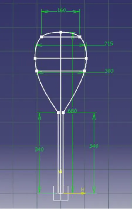
4.2.1 Dimensions and Isometric Drawing
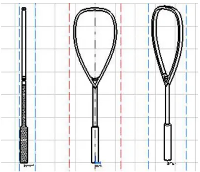
Figure 4.2 shows the dimension of squash racket frame; figure 4.3 shows the side view, front view and isometric view of the squash racket frame. This design will be used in the finite element analysis to improve the impact strength and to predict the failure mode for this squash racket frame design. This is the suitable design for squash racket due to its criteria.
26
Figure 4.2: Schematic diagram of squash racket frame
Figure 4.3: the side view, front view and isometric view of squash racket frame
27 4.3 Force
In this project, the force during the collision will be estimated by using the impulse – momentum theorem. The impulse – momentum theorem will be estimating the net force between the squash racket frame and wall during the collision by measuring the change in momentum that the impulse causes.
By using the formula Impulse – Momentum Theorem,
Assuming that the time of contact is 1.6 X 10⁻³ s.
Mass of the squash racket is 0.17 kg
Initial velocity of the squash racket is 150km/h
Final velocity of the squash racket is 270km/h
I = mv
f– mv
0I = (0.17)(270 X 0.2778) – (0.17)( – 150 X 0.2778)
= 12.751 + 7.084
= 19.835 kg.m/s
F = I/∆t
F = 19.835 kg.m/s / 1.6 X 10⁻³ s
= 12396.875 N
The force is positive, indicating that it points opposite to the velocity of the approaching wall.
So by using the impulse – momentum theorem, the force for this project is 12396.875 N will go to be used for the finite element analysis for the squash racket frame to improve the impact strength and also for improve the performance.
28 4.4 Finite Element Analysis
On this project, the static structural analysis is being used as it was the best analysis to study the stress distribution on the squash racket frame. There are three attempts that had been done as being experimented with the analysis. However, both of the attempts are not accurate analysis or results which will be discussed later attempt by attempt. On the attempt, the boundary conditions or environments of the static structural analysis on the squash racket can be divided into two parts which consists of Load and Conditions.
For Conditions, the thermal condition is the reference temperature that is 22°C.
4.4.1 Geometry
The geometry and dimension will be import form the CATIA® based the model Promark® PS-S 701 (figure 4.1).
4.4.2 Material Properties
The element of material being used for this racket is aluminium alloy. The material properties have shown in table 4.1. All the required information for ANSYS® to do the analysis have been shown.
4.4.3 Loading
For Load, it contains force, which is exerted on the frame amount of 24793.75 N. This is the assumption for the force that been hit the side of frame of the racket during doing the static structural analysis. The forces that will be two times higher than the force that is calculate by using the impulse – momentum theorem. The reason is because the impulse – momentum theorem is in the dynamic force. So to use in the static structural analysis the force should be higher than the force in dynamic situation. Also behind the one side frame analysis is just to test out the stress distribution as it will mirrored to the entire frame for the racket.
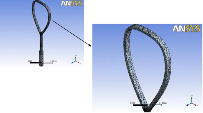
29 4.4.4 Meshing
Figure 4.4 show the meshing of squash racket frame using the ANSYS®. There are 54640 nodes and 36186 elements for this squash racket.
Figure 4.4: Meshing for squash racket frame 4.4.5 Static Structural Analysis
There are three attempts that had been done as being experimented with the analysis.
The different of this attempt it’s the location where the force will be apply for the static structural analysis. The location has been pick based on the location that has commonly will hit the wall during the game.
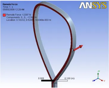
30 4.4.5.1 First Attempt
On first attempt, the force will be applied at the side of the squash racket frame as shown in figure 4.5.
Figure 4.5: First attempt for static structural analysis
For the results of the analysis of static structural, the parameters’ being examined is the equivalent (von-Mises) stress for the squash racket frame.
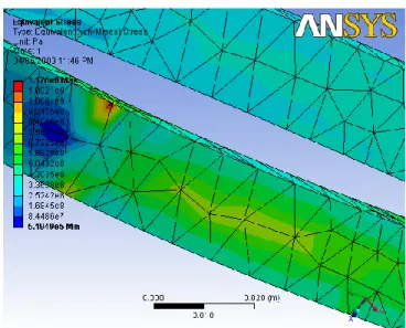
The result for equivalent (von-Mises) stress shown in figure 4.6. From figure 4.6, it’s shown there is deformation of the frame of squash racket. Form the force that have been applied to the squash racket frame, areas that resulting in high stress concentration were edges of the squash racket frame with shown in the figure 4.8, and side of the frame which can be seen as little yellowish and bluish areas as shown in figure 4.7. From the results, the minimum value of stress is 5.1949e5 Pa while the maximum is 1.176e9 Pa.
31
Figure 4.6: Equivalent (von-Mises) stress for squash racket frame
Figure 4.7: Maximum stress’s location in equivalent (von-Mises) stress With element Without element
32 4.4.5.2 Second Attempt
On second attempt, the force will be applied at the side of the squash racket frame as shown in figure 4.8.
Figure 4.8: Second attempt for static structural analysis
For the results of the analysis of static structural, the parameters’ being examined is the equivalent (von-Mises) stress for the squash racket frame.
The result for equivalent (von-Mises) stress shown in figure 4.9. For the second attempt, it’s also shown there is deformation of the frame of squash racket. Also form the force that have been applied to the squash racket frame, areas that resulting in high stress concentration were the edges of the squash racket frame with shown in the figure 4.10, and side of the frame which can be seen as little yellowish and bluish areas as shown in figure 4.19. From the results, the minimum value of stress is 3.7696e5 Pa while the maximum is 2.2177e9 Pa.
33
Figure 4.9: Equivalent (von-Mises) stress for squash racket frame
Figure 4.10: Maximum stress’s location in equivalent (von-Mises) stress With element Without element
34 4.4.5.3 Third Attempt
On third attempt, the force will be applied at the side of the squash racket frame as shown in figure 4.11.
Figure 4.11: Third attempt for static structural analysis
For the third attempt, equivalent (von-Mises) stress will be examiner the third attempt.
The result for equivalent (von-Mises) stress shown in figure 4.12. For the third attempt, it’s also shown there is deformation of the frame of squash racket. Also form the force that have been applied to the squash racket frame, areas that resulting in high stress concentration were the edges of the squash racket frame with shown in the figure 4.13, and side of the frame which can be seen as little yellowish and bluish areas as shown in figure 4.12. From the results, the minimum value of stress is 3.1257e5 Pa while the maximum is 1.458e9 Pa.
35
Figure 4.12: Equivalent (von-Mises) stress for squash racket frame
Figure 4.13: Maximum stress’s location in equivalent (von-Mises) stress With element Without element
36 4.4.6 Stress Data
Table 4.2: Minimum and Maximum Stress
Minimum Stress Maximum Stress
First Attempt 5.1949e5 Pa 1.176e9 Pa
Second Attempt 3.7696e5 Pa 2.2177e9Pa.
Third Attempt 3.1257e5 Pa 1.458e9 Pa
4.5 FEA Data Analysis
Based on the static structural analysis data above, the figure 4.7, 4.10, 4.13 showed that the force at the edge of the squash racket frame as shown all the attempt have the high stress concentration. A stress concentration factor is a ratio of the greatest stress in the area of a notch or other stress raiser to the corresponding nominal stress or reference stress of the gross cross-section. Based on the analysis using the Finite Element Analysis, its show that the edge of the squash racket frame as shown in the figure 4.7, 4.10, 4.13 has a maximum stress that indicate the crack at that part because of the stress.
This will predict the possible failure mode for the squash racket frame
37
CHAPTER 5
CONCLUSION AND RECOMMENDATION
5.1 Conclusion
In conclusion, throughout the result from the analysis, improvement of models and attachments shape will be made to verify the characteristic and effect of attachments to improve the impact strength of squash racket frame. One of important factor to archive the similarity is fine design based on characteristic and it is have low stress concentration and also stress concentration factor proven in analysis conducted. Predict the failure mode for the squash racket frame also can improve the design to achieve the objective to improve the impact strength for the squash racket frame. The studies can be the inaccurate decision of determining the right environment or boundary conditions that should be experience by squash racket frame. Similarity between model and actual racket must be obtained as it is very crucial. ANSYS plays an important steps before proceeding with the analysis as it will be taken into the mathematical model that being solved by computer which will affecting the results. A lot of research, initiatives and efforts have been focused in order to accomplish the improvement of impact strength and to predict the failure mode for the squash racket frame.
38 5.2 Recommendation
As the project going on to the end the design and fabrication of optimum shape of attachments to squash racket that can reduce the stress concentration factor will achieved. The design for the squash racket frame can be modified and using different material of squash racket frame to reduce the stress concentration factor. Hence it will give the better performance for the player who used this racket. Therefore, further study and practice with ANSYS are needed in order to complete the analysis with the most accurate results.