Oracle® Fusion Middleware
Using Clusters for Oracle WebLogic Server
11
g
Release 1 (10.3.5)
E13709-05
April 2011
Copyright © 2007, 2011, Oracle and/or its affiliates. All rights reserved.
This software and related documentation are provided under a license agreement containing restrictions on use and disclosure and are protected by intellectual property laws. Except as expressly permitted in your license agreement or allowed by law, you may not use, copy, reproduce, translate, broadcast, modify, license, transmit, distribute, exhibit, perform, publish, or display any part, in any form, or by any means. Reverse engineering, disassembly, or decompilation of this software, unless required by law for interoperability, is prohibited.
The information contained herein is subject to change without notice and is not warranted to be error-free. If you find any errors, please report them to us in writing.
If this software or related documentation is delivered to the U.S. Government or anyone licensing it on behalf of the U.S. Government, the following notice is applicable:
U.S. GOVERNMENT RIGHTS Programs, software, databases, and related documentation and technical data delivered to U.S. Government customers are "commercial computer software" or "commercial technical data" pursuant to the applicable Federal Acquisition Regulation and agency-specific supplemental regulations. As such, the use, duplication, disclosure, modification, and adaptation shall be subject to the restrictions and license terms set forth in the applicable Government contract, and, to the extent applicable by the terms of the Government contract, the additional rights set forth in FAR 52.227-19, Commercial Computer Software License (December 2007). Oracle USA, Inc., 500 Oracle Parkway, Redwood City, CA 94065.
This software is developed for general use in a variety of information management applications. It is not developed or intended for use in any inherently dangerous applications, including applications which may create a risk of personal injury. If you use this software in dangerous applications, then you shall be responsible to take all appropriate fail-safe, backup, redundancy, and other measures to ensure the safe use of this software. Oracle Corporation and its affiliates disclaim any liability for any damages caused by use of this software in dangerous applications.
Oracle is a registered trademark of Oracle Corporation and/or its affiliates. Other names may be trademarks of their respective owners.
Contents
Preface
... xvDocumentation Accessibility ... xv
Conventions ... xv
1
Introduction and Roadmap
1.1 Document Scope and Audience... 1-1 1.2 Guide to this Document ... 1-1 1.3 Related Documentation... 1-2 1.4 New and Changed Clustering Features in This Release ... 1-2
2
Understanding WebLogic Server Clustering
2.1 What Is a WebLogic Server Cluster?... 2-1 2.2 How Does a Cluster Relate to a Domain? ... 2-1 2.3 What Are the Benefits of Clustering?... 2-2 2.4 What Are the Key Capabilities of a Cluster? ... 2-2 2.5 What Types of Objects Can Be Clustered? ... 2-4 2.5.1 Servlets and JSPs ... 2-4 2.5.2 EJBs and RMI Objects... 2-5 2.5.3 JDBC Connections... 2-5 2.5.3.1 Getting Connections with Clustered JDBC... 2-6 2.5.3.2 Failover and Load Balancing for JDBC Connections ... 2-6 2.5.4 JMS and Clustering... 2-6 2.6 What Types of Objects Cannot Be Clustered? ... 2-7
3
Communications In a Cluster
3.1.3.2 Configuring Reader Threads for Java Socket Implementation... 3-6 3.1.3.2.1 Determining Potential Socket Usage ... 3-6 3.1.4 Client Communication via Sockets ... 3-7 3.2 Cluster-Wide JNDI Naming Service ... 3-8 3.2.1 How WebLogic Server Creates the Cluster-Wide JNDI Tree... 3-8 3.2.2 How JNDI Naming Conflicts Occur ... 3-10 3.2.2.1 Deploy Homogeneously to Avoid Cluster-Level JNDI Conflicts ... 3-10 3.2.3 How WebLogic Server Updates the JNDI Tree... 3-11 3.2.4 Client Interaction with the Cluster-Wide JNDI Tree ... 3-11
4
Understanding Cluster Configuration
4.1 Cluster Configuration and config.xml ... 4-1 4.2 Role of the Administration Server... 4-1 4.2.1 What Happens if the Administration Server Fails?... 4-3 4.3 How Dynamic Configuration Works... 4-3 4.4 Application Deployment for Clustered Configurations ... 4-4 4.4.1 Deployment Methods... 4-4 4.4.2 Introduction to Two-Phase Deployment... 4-5 4.4.2.1 First Phase of Deployment ... 4-5 4.4.2.2 Second Phase of Deployment ... 4-5 4.4.3 Guidelines for Deploying to a Cluster ... 4-5 4.4.3.1 WebLogic Server Supports "Relaxed Deployment" Rules... 4-6 4.4.3.1.1 Deployment to a Partial Cluster is Allowed... 4-6 4.4.3.1.2 Deploying to Complete Clusters in WebLogic Server ... 4-6 4.4.3.1.3 Pinned Services can be Deployed to Multiple Managed Servers... 4-6 4.5 Methods of Configuring Clusters ... 4-7
5
Load Balancing in a Cluster
5.2.5 Parameter-Based Routing for Clustered Objects... 5-9 5.2.6 Optimization for Collocated Objects... 5-9 5.2.6.1 Transactional Collocation... 5-10 5.3 Load Balancing for JMS... 5-11 5.3.1 Server Affinity for Distributed JMS Destinations ... 5-12 5.3.2 Initial Context Affinity and Server Affinity for Client Connections ... 5-12 5.4 Load Balancing for JDBC Connections ... 5-13
6
Failover and Replication in a Cluster
6.3.2.2.2 Stateful Session Beans... 6-21 6.3.2.2.3 Failover for Stateful Session EJBs... 6-22 6.3.2.3 Entity EJBs ... 6-23 6.3.2.3.1 Failover for Entity Beans and EJB Handles ... 6-23 6.3.3 Clustering Support for RMI Objects ... 6-23 6.3.4 Object Deployment Requirements ... 6-24 6.3.4.1 Other Failover Exceptions ... 6-24 6.4 Failover and JDBC Connections ... 6-24
7
Whole Server Migration
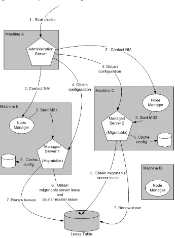
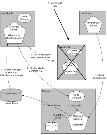
7.1 Understanding Server and Service Migration ... 7-1 7.2 Migration Terminology... 7-2 7.3 Leasing... 7-3 7.3.1 Features That Use Leasing... 7-3 7.3.2 Leasing Versions ... 7-3 7.3.3 Determining Which Type of Leasing To Use ... 7-4 7.3.4 High-availability Database Leasing ... 7-4 7.3.5 Non-database Consensus Leasing... 7-5 7.4 Automatic Whole Server Migration ... 7-6 7.4.1 Preparing for Automatic Whole Server Migration ... 7-6 7.4.2 Configuring Automatic Whole Server Migration ... 7-7 7.4.3 Using High Availability Storage for State Data ... 7-9 7.4.4 Server Migration Processes and Communications ... 7-9 7.4.4.1 Startup Process in a Cluster with Migratable Servers... 7-9 7.4.4.2 Automatic Whole Server Migration Process ... 7-11 7.4.4.3 Manual Whole Server Migration Process ... 7-12 7.4.4.4 Administration Server Role in Whole Server Migration ... 7-13 7.4.4.5 Migratable Server Behavior in a Cluster ... 7-14 7.4.4.6 Node Manager Role in Whole Server Migration ... 7-14 7.4.4.7 Cluster Master Role in Whole Server Migration... 7-15
8
Service Migration
8.1.2.5 Targeting Rules for JMS Servers... 8-6 8.1.2.6 Targeting Rules for SAF Agents... 8-7 8.1.2.6.1 Re-targeting SAF Agents to Migratable Targets... 8-7 8.1.2.6.2 Targeting Migratable SAF Agents For Increased Message Throughput ... 8-7 8.1.2.6.3 Targeting SAF Agents For Consistent Quality-of-Service... 8-7 8.1.2.7 Targeting Rules for Path Service ... 8-7 8.1.2.7.1 Special Considerations For Targeting a Path Service... 8-7 8.1.2.8 Targeting Rules for Custom Stores ... 8-8 8.1.2.9 Migratable Targets For the JTA Transaction Recovery Service ... 8-8 8.1.3 Migration Processing Tools... 8-8 8.1.3.1 Administration Console ... 8-8 8.1.3.2 WebLogic Scripting Tool ... 8-8 8.1.4 Automatic Service Migration Infrastructure ... 8-9 8.1.4.1 Leasing for Migratable Services ... 8-9 8.1.4.1.1 Database Leasing... 8-9 8.1.4.1.2 Consensus Leasing ... 8-9 8.1.4.2 Node Manager ... 8-9 8.1.4.3 Administration Server Not Required When Migrating Services ... 8-9 8.1.4.4 Service Health Monitoring ... 8-10 8.1.4.4.1 How Health Monitoring of the JTA Transaction Recovery Service Triggers
Automatic Migration 8-10
8.1.4.4.2 How Health Monitoring of JMS-related Services Triggers Automatic Migration 8-10
8.1.5 In-Place Restarting of Failed Migratable Services... 8-11 8.1.6 Migrating a Service From an Unavailable Server ... 8-11 8.1.7 JMS and JTA Automatic Service Migration Interaction ... 8-11 8.2 Pre-Migration Requirements... 8-11 8.2.1 Custom Store Availability for JMS Services... 8-12 8.2.2 Default File Store Availability for JTA... 8-12 8.2.3 Server State and Manual Service Migration ... 8-13 8.3 Roadmap for Configuring Automatic Migration of JMS-related Services ... 8-13 8.3.1 Step 1: Configured Managed Servers and Node Manager... 8-14 8.3.2 Step 2: Configure the Migration Leasing Basis... 8-14 8.3.3 Step 3: Configure Migratable Targets ... 8-14 8.3.3.1 Configuring a Migratable Server as an Automatically Migratable Target ... 8-14 8.3.3.2 Create a New Migratable Target ... 8-14 8.3.3.2.1 Select a User Preferred Server ... 8-15 8.3.3.2.2 Select a Service Migration Policy ... 8-15 8.3.3.2.3 Optionally Select Constrained Candidate Servers ... 8-15 8.3.3.2.4 Optionally Specify Pre/Post-Migration Scripts... 8-16 8.3.3.2.5 Optionally Specify In-Place Restart Options... 8-16 8.3.4 Step 4: Configure and Target Custom Stores... 8-16 8.3.5 Step 5: Target the JMS Services... 8-16 8.3.5.1 Special Considerations When Targeting SAF Agents or Path Service ... 8-17 8.3.6 Step 6: Restart the Administration Server and Managed Servers With Modified
8.5.1 Step 1: Configured Managed Servers ... 8-18 8.5.2 Step 2: Configure Migratable Targets ... 8-19 8.5.2.1 Configuring a Migratable Server As a Migratable Target ... 8-19 8.5.2.2 Create a New Migratable Target ... 8-19 8.5.2.2.1 Select a Preferred Server... 8-19 8.5.2.2.2 Accept the Default Manual Service Migration Policy... 8-19 8.5.2.2.3 Optionally Select Constrained Candidate Servers ... 8-19 8.5.2.2.4 Optionally Specify Pre/Post-Migration Scripts... 8-19 8.5.2.2.5 Optionally Specify In-Place Restart Options... 8-20 8.5.3 Step 3: Configure and Target Custom Stores... 8-20 8.5.4 Step 4: Target the JMS Services... 8-20 8.5.4.1 Special Considerations When Targeting SAF Agents or Path Service ... 8-20 8.5.5 Step 5: Restart the Administration Server and Managed Servers With Modified
Migration Policies 8-20
8.5.6 Step 6: Manually Migrating JMS Services ... 8-21 8.6 Roadmap for Configuring Automatic Migration of the JTA Transaction Recovery Service...
8-21
8.6.1 Step 1: Configured Managed Servers and Node Manager... 8-21 8.6.2 Step 2: Configure the Migration Basis ... 8-22 8.6.3 Step 3: Enable Automatic JTA Migration ... 8-22 8.6.3.1 Select the Automatic JTA Migration Check Box ... 8-22 8.6.3.2 Optionally Select Candidate Servers ... 8-22 8.6.3.3 Optionally Specify Pre/Post-Migration Scripts ... 8-22 8.6.4 Step 4: Configure the Default Persistent Store For Transaction Recovery Service
Migration 8-23
8.6.5 Step 5: Restart the Administration Server and Managed Servers With Modified Migration Policies 8-23
8.6.6 Step 6: Automatic Failback of the Transaction Recovery Service Back to the Original Server 8-23
8.7 Manual Migration of the JTA Transaction Recovery Service ... 8-24 8.8 Automatic Migration of User-Defined Singleton Services ... 8-24 8.8.1 Overview of Singleton Service Migration ... 8-24 8.8.1.1 Singleton Master ... 8-25 8.8.1.2 Migration Failure... 8-25 8.8.2 Implementing the Singleton Service Interface... 8-25 8.8.3 Deploying a Singleton Service and Configuring the Migration Behavior ... 8-26 8.8.3.1 Packaging and Deploying a Singleton Service Within an Application ... 8-26 8.8.3.2 Deploying a Singleton Service as a Standalone Service in WebLogic Server ... 8-26 8.8.3.3 Configuring Singleton Service Migration ... 8-27
9
Cluster Architectures
9.1.5 Load Balancer ... 9-2 9.1.6 Proxy Plug-In... 9-2 9.2 Recommended Basic Architecture... 9-2 9.2.1 When Not to Use a Combined Tier Architecture... 9-4 9.3 Recommended Multi-Tier Architecture ... 9-4 9.3.1 Physical Hardware and Software Layers ... 9-5 9.3.1.1 Web/Presentation Layer ... 9-5 9.3.1.2 Object Layer... 9-5 9.3.2 Benefits of Multi-Tier Architecture ... 9-5 9.3.3 Load Balancing Clustered Objects in a in Multi-Tier Architecture ... 9-6 9.3.4 Configuration Considerations for Multi-Tier Architecture... 9-8 9.3.4.1 IP Socket Usage... 9-8 9.3.4.2 Hardware Load Balancers... 9-8 9.3.5 Limitations of Multi-Tier Architectures ... 9-8 9.3.5.1 No Collocation Optimization... 9-8 9.3.5.2 Firewall Restrictions... 9-9 9.4 Recommended Proxy Architectures ... 9-9 9.4.1 Two-Tier Proxy Architecture ... 9-9 9.4.1.1 Physical Hardware and Software Layers... 9-10 9.4.1.1.1 Web Layer... 9-10 9.4.1.1.2 Servlet/Object Layer... 9-10 9.4.2 Multi-Tier Proxy Architecture ... 9-11 9.4.3 Proxy Architecture Benefits... 9-11 9.4.4 Proxy Architecture Limitations ... 9-12 9.4.5 Proxy Plug-In Versus Load Balancer ... 9-12 9.5 Security Options for Cluster Architectures... 9-12 9.5.1 Basic Firewall for Proxy Architectures ... 9-12 9.5.1.1 Firewall Between Proxy Layer and Cluster ... 9-13 9.5.1.2 DMZ with Basic Firewall Configurations ... 9-14 9.5.1.3 Combining Firewall with Load Balancer ... 9-14 9.5.1.4 Expanding the Firewall for Internal Clients ... 9-15 9.5.2 Additional Security for Shared Databases ... 9-16 9.5.2.1 DMZ with Two Firewall Configuration... 9-16
10
Setting up WebLogic Clusters
10.1.5.3 Administration Server Address and Port ... 10-4 10.1.5.4 Managed Server Addresses and Listen Ports... 10-4 10.1.5.5 Cluster Multicast Address and Port ... 10-4 10.1.5.5.1 Multicast and Multiple Clusters ... 10-4 10.1.5.5.2 Multicast and Multi-Tier Clusters... 10-4 10.1.5.6 Cluster Address ... 10-4 10.1.5.6.1 Dynamic Cluster Address ... 10-5 10.1.5.6.2 Explicitly Defining Cluster Address for Production Environments... 10-5 10.1.5.6.3 Explicitly Defining Cluster Address for Development and Test Environments .
10-6
10.2.17 Configure In-Memory HTTP Replication ... 10-23 10.2.18 Additional Configuration Topics ... 10-24 10.2.18.1 Configure IP Sockets ... 10-24 10.2.18.1.1 Configure Native IP Sockets Readers on Machines that Host Server Instances ..
10-24
10.2.18.1.2 Set the Number of Reader Threads on Machines that Host Server Instances...
10-25
10.2.18.1.3 Set the Number of Reader Threads on Client Machines ... 10-25 10.2.18.2 Configure Multicast Time-To-Live (TTL) ... 10-25 10.2.18.3 Configure Multicast Buffer Size ... 10-26 10.2.18.4 Configure Multicast Data Encryption ... 10-26 10.2.18.5 Configure Machine Names ... 10-26 10.2.18.6 Configuration Notes for Multi-Tier Architecture ... 10-27 10.2.18.7 Enable URL Rewriting ... 10-27
11
Clustering Best Practices
11.1 General Design Considerations ... 11-1 11.1.1 Strive for Simplicity... 11-1 11.1.2 Minimize Remote Calls... 11-1 11.1.2.1 Session Facades Reduce Remote Calls ... 11-1 11.1.2.2 Transfer Objects Reduce Remote Calls... 11-1 11.1.2.3 Distributed Transactions Increase Remote Calls ... 11-2 11.2 Web Application Design Considerations ... 11-2 11.2.1 Configure In-Memory Replication ... 11-2 11.2.2 Design for Idempotence ... 11-2 11.2.3 Programming Considerations... 11-2 11.3 EJB Design Considerations ... 11-2 11.3.1 Design Idempotent Methods... 11-2 11.3.2 Follow Usage and Configuration Guidelines ... 11-3 11.3.2.1 Cluster-Related Configuration Options ... 11-4 11.4 State Management in a Cluster ... 11-5 11.5 Application Deployment Considerations... 11-9 11.6 Architecture Considerations ... 11-9 11.7 Avoiding Problems... 11-9 11.7.1 Naming Considerations... 11-9 11.7.2 Administration Server Considerations... 11-9 11.7.3 Firewall Considerations ... 11-10 11.7.4 Evaluate Cluster Capacity Prior to Production Use ... 11-11
12
Troubleshooting Common Problems
12.2.3 Check Garbage Collection ... 12-3 12.2.4 Run utils.MulticastTest ... 12-3
13
Troubleshooting Multicast Configuration
13.1 Verifying Multicast Address and Port Configuration... 13-1 13.1.1 Possible Errors... 13-2 13.1.2 Checking the Multicast Address and Port ... 13-2 13.2 Identifying Network Configuration Problems ... 13-2 13.2.1 Physical Connections ... 13-2 13.2.2 Address Conflicts... 13-2 13.2.3 nsswitch.conf Settings on UNIX Systems... 13-2 13.3 Using the MulticastTest Utility ... 13-2 13.4 Tuning Multicast Features ... 13-3 13.4.1 Multicast Timeouts ... 13-3 13.4.2 Cluster Heartbeats ... 13-3 13.4.2.1 Multicast Send Delay ... 13-3 13.4.2.2 Operating System Parameters ... 13-3 13.4.3 Multicast Storms ... 13-4 13.4.4 Multicast and Multihomed Machines... 13-4 13.4.5 Multicast in Different Subnets ... 13-4 13.5 Debugging Multicast ... 13-4 13.5.1 Debugging Utilities ... 13-4 13.5.1.1 MulticastMonitor ... 13-4 13.5.1.2 MulticastTest ... 13-5 13.5.2 Debugging Flags ... 13-5 13.5.2.1 Setting Debug Flags on the Command Line... 13-5 13.5.2.2 Setting Debug Attributes Using WLST ... 13-5 13.6 Miscellaneous Issues... 13-5 13.6.1 Multicast on AIX ... 13-5 13.6.2 File Descriptor Problems ... 13-6 13.7 Other Resources for Troubleshooting Multicast Configuration ... 13-6
A
The WebLogic Cluster API
A.1 How to Use the API ... A-1 A.2 Custom Call Routing and Collocation Optimization ... A-2
B
Configuring BIG-IP Hardware with Clusters
C
Configuring F5 Load Balancers for MAN/WAN Failover
C.3 Configure the 3-DNS Global Hardware Load Balancer... C-3 C.3.1 Configure DNS Zones ... C-4 C.3.2 Configure BIG-IP Addresses Managed by 3-DNS... C-4 C.3.3 Configure Data Centers ... C-4 C.3.4 Configure Wide IPs ... C-4 C.4 Configuring WebLogic Server Components... C-5
D
Configuring Radware Load Balancers for MAN/WAN Failover
Preface
This preface describes the document accessibility features and conventions used in this guide—Using Clusters for Oracle WebLogic Server.
Documentation Accessibility
Our goal is to make Oracle products, services, and supporting documentation accessible to all users, including users that are disabled. To that end, our
documentation includes features that make information available to users of assistive technology. This documentation is available in HTML format, and contains markup to facilitate access by the disabled community. Accessibility standards will continue to evolve over time, and Oracle is actively engaged with other market-leading
technology vendors to address technical obstacles so that our documentation can be accessible to all of our customers. For more information, visit the Oracle Accessibility Program Web site at http://www.oracle.com/accessibility/.
Accessibility of Code Examples in Documentation
Screen readers may not always correctly read the code examples in this document. The conventions for writing code require that closing braces should appear on an
otherwise empty line; however, some screen readers may not always read a line of text that consists solely of a bracket or brace.
Accessibility of Links to External Web Sites in Documentation
This documentation may contain links to Web sites of other companies or
organizations that Oracle does not own or control. Oracle neither evaluates nor makes any representations regarding the accessibility of these Web sites.
Access to Oracle Support
Oracle customers have access to electronic support through My Oracle Support. For information, visit http://www.oracle.com/support/contact.html or visit
http://www.oracle.com/accessibility/support.html if you are hearing impaired.
Conventions
The following text conventions are used in this document:
which you supply particular values.
1
1
Introduction and Roadmap
This section describes the contents and organization of this guide—Using WebLogic Server Clusters.
■ Section 1.1, "Document Scope and Audience" ■ Section 1.2, "Guide to this Document" ■ Section 1.3, "Related Documentation"
■ Section 1.4, "New and Changed Clustering Features in This Release"
1.1 Document Scope and Audience
This document is written for application developers and administrators who are developing or deploying Web-based applications on one or more clusters. It also contains information that is useful for business analysts and system architects who are evaluating WebLogic Server or considering the use of WebLogic Server clusters for a particular application.
The topics in this document are primarily relevant to planning, implementing, and supporting a production environment that includes WebLogic Server clusters. Key guidelines for software engineers who design or develop applications that will run on a WebLogic Server cluster are also addressed.
It is assumed that the reader is familiar with Java EE, HTTP, HTML coding, and Java programming (servlets, JSP, or EJB development).
1.2 Guide to this Document
■ This chapter, Chapter 1, "Introduction and Roadmap," describes the organization
of this guide.
■ Chapter 2, "Understanding WebLogic Server Clustering," provides a brief
introduction to WebLogic Server clusters.
■ Chapter 3, "Communications In a Cluster," describes how WebLogic Server
instances communicate to one another in a cluster and how they utilize a cluster-wide JNDI tree.
■ Chapter 4, "Understanding Cluster Configuration," explains how the information
that defines the configuration of a cluster is stored and maintained, and identifies the methods you can use to accomplish cluster configuration tasks.
■ Chapter 6, "Failover and Replication in a Cluster," describes how WebLogic Server
detects failures in a cluster, and summarizes how failover is accomplished for different types of objects.
■ Chapter 7, "Whole Server Migration," describes the different migration
mechanisms supported by WebLogic Server.
■ Chapter 8, "Service Migration," describes the service migration mechanisms
supported by WebLogic Server:
■ Chapter 9, "Cluster Architectures," describes alternative architectures for a
WebLogic Server cluster.
■ Chapter 10, "Setting up WebLogic Clusters," contains guidelines and instructions
for configuring a WebLogic Server cluster.
■ Chapter 11, "Clustering Best Practices," provides recommendations for design and
deployment practices that maximize the scalability, reliability, and performance of applications hosted by a WebLogic Server cluster.
■ Chapter 12, "Troubleshooting Common Problems," provides guidelines on how to
prevent and troubleshoot common cluster problems.
■ Appendix A, "The WebLogic Cluster API," describes the WebLogic Cluster API. ■ Appendix B, "Configuring BIG-IP Hardware with Clusters," describes options for
configuring an F5 BIG-IP controller to operate with a WebLogic Server cluster.
■ Appendix C, "Configuring F5 Load Balancers for MAN/WAN Failover," explains
how to configure F5 hardware load balancers.
■ Appendix D, "Configuring Radware Load Balancers for MAN/WAN Failover,"
describes how to configure Radware hardware load balancers.
1.3 Related Documentation
■ "Understanding Enterprise JavaBeans" in Programming WebLogic Enterprise
JavaBeans for Oracle WebLogic Server
■ "Creating and Configuring Web Applications" in Developing Web Applications,
Servlets, and JSPs for Oracle WebLogic Server.
1.4 New and Changed Clustering Features in This Release
2
2
Understanding WebLogic Server Clustering
This section is a brief introduction to WebLogic Server clusters. It contains the following information:
■ Section 2.1, "What Is a WebLogic Server Cluster?" ■ Section 2.2, "How Does a Cluster Relate to a Domain?" ■ Section 2.3, "What Are the Benefits of Clustering?" ■ Section 2.4, "What Are the Key Capabilities of a Cluster?" ■ Section 2.5, "What Types of Objects Can Be Clustered?" ■ Section 2.6, "What Types of Objects Cannot Be Clustered?"
2.1 What Is a WebLogic Server Cluster?
A WebLogic Server cluster consists of multiple WebLogic Server server instances running simultaneously and working together to provide increased scalability and reliability. A cluster appears to clients to be a single WebLogic Server instance. The server instances that constitute a cluster can run on the same machine, or be located on different machines. You can increase a cluster's capacity by adding additional server instances to the cluster on an existing machine, or you can add machines to the cluster to host the incremental server instances. Each server instance in a cluster must run the same version of WebLogic Server.
2.2 How Does a Cluster Relate to a Domain?
A cluster is part of a particular WebLogic Server domain.
A domain is an interrelated set of WebLogic Server resources that are managed as a unit. A domain includes one or more WebLogic Server instances, which can be clustered, non-clustered, or a combination of clustered and non-clustered instances. A domain can include multiple clusters. A domain also contains the application
components deployed in the domain, and the resources and services required by those application components and the server instances in the domain. Examples of the resources and services used by applications and server instances include machine definitions, optional network channels, connectors, and startup classes.
In each domain, one WebLogic Server instance acts as the Administration Server—the server instance which configures, manages, and monitors all other server instances and resources in the domain. Each Administration Server manages one domain only. If a domain contains multiple clusters, each cluster in the domain has the same
Administration Server.
All server instances in a cluster must reside in the same domain; you cannot "split" a cluster over multiple domains. Similarly, you cannot share a configured resource or subsystem between domains. For example, if you create a JDBC connection pool in one domain, you cannot use it with a server instance or cluster in another domain.
(Instead, you must create a similar connection pool in the second domain.)
Clustered WebLogic Server instances behave similarly to non-clustered instances, except that they provide failover and load balancing. The process and tools used to configure clustered WebLogic Server instances are the same as those used to configure non-clustered instances. However, to achieve the load balancing and failover benefits that clustering enables, you must adhere to certain guidelines for cluster configuration.
To understand how the failover and load balancing mechanisms used in WebLogic Server relate to particular configuration options see Section 5, "Load Balancing in a Cluster," and Section 6, "Failover and Replication in a Cluster."
Detailed configuration recommendations are included throughout the instructions in
Section 10, "Setting up WebLogic Clusters".
2.3 What Are the Benefits of Clustering?
A WebLogic Server cluster provides these benefits:
■ Scalability
The capacity of an application deployed on a WebLogic Server cluster can be increased dynamically to meet demand. You can add server instances to a cluster without interruption of service—the application continues to run without impact to clients and end users.
■ High-Availability
In a WebLogic Server cluster, application processing can continue when a server instance fails. You "cluster" application components by deploying them on multiple server instances in the cluster—so, if a server instance on which a component is running fails, another server instance on which that component is deployed can continue application processing.
The choice to cluster WebLogic Server instances is transparent to application developers and clients. However, understanding the technical infrastructure that enables clustering will help programmers and administrators maximize the scalability and availability of their applications.
2.4 What Are the Key Capabilities of a Cluster?
This section defines, in non-technical terms, the key clustering capabilities that enable scalability and high availability.
■ Application Failover
What Are the Key Capabilities of a Cluster?
For the new object to be able to take over for the failed object:
– There must be a copy of the failed object available to take over the job.
– There must be information, available to other objects and the program that manages failover, defining the location and operational status of all
objects—so that it can be determined that the first object failed before finishing its job.
– There must be information, available to other objects and the program that manages failover, about the progress of jobs in process—so that an object taking over an interrupted job knows how much of the job was completed before the first object failed, for example, what data has been changed, and what steps in the process were completed.
WebLogic Server uses standards-based communication techniques and facilities— including IP sockets and the Java Naming and Directory Interface (JNDI)—to share and maintain information about the availability of objects in a cluster. These techniques allow WebLogic Server to determine that an object stopped before finishing its job, and where there is a copy of the object to complete the job that was interrupted.
Information about what has been done on a job is called state. WebLogic Server maintains information about state using techniques called session replication and replica-aware stubs. When a particular object unexpectedly stops doing its job, replication techniques enable a copy of the object pick up where the failed object stopped, and finish the job.
■ WebLogic Server supports automatic and manual migration of a clustered server
instance from one machine to another. A Managed Server that can be migrated is referred to as a migratable server. This feature is designed for environments with requirements for high availability. The server migration capability is useful for:
– Ensuring uninterrupted availability of singleton services—services that must run on only a single server instance at any given time, such as JMS and the JTA transaction recovery system, when the hosting server instance fails. A Managed Server configured for automatic migration will be automatically migrated to another machine in the event of failure.
– Easing the process of relocating a Managed Server, and all the services it hosts, as part of a planned system administration process. An administrator can initiate the migration of a Managed Server from the Administration Console or command line.
The server migration process relocates a Managed Server in its entirety—including IP addresses and hosted applications—to one of a predefined set of available host machines.
■ Load Balancing
Load balancing is the even distribution of jobs and associated communications across the computing and networking resources in your environment. For load balancing to occur:
– Information about the location and operational status of all objects must be available.
WebLogic Server allows objects to be clustered—deployed on multiple server instances—so that there are alternative objects to do the same job. WebLogic Server shares and maintains the availability and location of deployed objects using unicast, IP sockets, and JNDI.
A detailed discussion of how communications and replication techniques are employed by WebLogic Server is provided in Section 3, "Communications In a Cluster."
2.5 What Types of Objects Can Be Clustered?
A clustered application or application component is one that is available on multiple WebLogic Server instances in a cluster. If an object is clustered, failover and load balancing for that object is available. Deploy objects homogeneously—to every server instance in your cluster—to simplify cluster administration, maintenance, and troubleshooting.
Web applications can consist of different types of objects, including Enterprise Java Beans (EJBs), servlets, and Java Server Pages (JSPs). Each object type has a unique set of behaviors related to control, invocation, and how it functions within an application. For this reason, the methods that WebLogic Server uses to support clustering—and hence to provide load balancing and failover—can vary for different types of objects. The following types of objects can be clustered in a WebLogic Server deployment:
■ Servlets ■ JSPs ■ EJBs
■ Remote Method Invocation (RMI) objects ■ Java Messaging Service (JMS) destinations ■ Java Database Connectivity (JDBC) connections
Different object types can have certain behaviors in common. When this is the case, the clustering support and implementation considerations for those similar object types may be same. In the sections that follow, explanations and instructions for the following types of objects are generally combined:
■ Servlets and JSPs ■ EJBs and RMI objects
The sections that follow briefly describe the clustering, failover, and load balancing support that WebLogic Server provides for different types of objects.
2.5.1 Servlets and JSPs
WebLogic Server provides clustering support for servlets and JSPs by replicating the HTTP session state of clients that access clustered servlets and JSPs. WebLogic Server can maintain HTTP session states in memory, a file system, or a database.
What Types of Objects Can Be Clustered?
To enable automatic failover of servlets and JSPs, session state must persist in memory. For information about how failover works for servlets and JSPs, and for related requirements and programming considerations, see Section 6.2.1, "HTTP Session State Replication."
You can balance the servlet and JSP load across a cluster using a WebLogic Server proxy plug-in or external load balancing hardware. WebLogic Server proxy plug-ins perform round-robin load balancing. External load balancers typically support a variety of session load balancing mechanisms. For more information, see Section 5.1, "Load Balancing for Servlets and JSPs."
2.5.2 EJBs and RMI Objects
Load balancing and failover for EJBs and RMI objects is handled using replica-aware stubs, which can locate instances of the object throughout the cluster. Replica-aware stubs are created for EJBs and RMI objects as a result of the object compilation process. EJBs and RMI objects are deployed homogeneously—to all the server instances in the cluster.
Failover for EJBs and RMI objects is accomplished using the object's replica-aware stub. When a client makes a call through a replica-aware stub to a service that fails, the stub detects the failure and retries the call on another replica. To understand failover support for different types of objects, see Section 6.3, "Replication and Failover for EJBs and RMIs."
WebLogic Server clusters support multiple algorithms for load balancing clustered EJBs and RMI objects: round-robin, weight-based, random, round-robin-affinity, weight-based-affinity, and random-affinity. By default, a WebLogic Server cluster will use the round-robin method. You can configure a cluster to use one of the other methods using the Administration Console. The method you select is maintained within the replica-aware stub obtained for clustered objects. For details, see Section 5.2, "Load Balancing for EJBs and RMI Objects."
2.5.3 JDBC Connections
WebLogic Server allows you to cluster JDBC objects, including data sources and multi data sources, to improve the availability of cluster-hosted applications. Each JDBC object you configure for your cluster must exist on each Managed Server in the cluster—when you configure the JDBC objects, target them to the cluster.
■ Data Sources—In a cluster, external clients must obtain connections through a
JDBC data source on the JNDI tree. The data source uses the WebLogic Server RMI driver to acquire a connection. The cluster-aware nature of WebLogic data sources in external client applications allows a client to request another connection if the server instance hosting the previous connection fails. Although not strictly required, Oracle recommends that server-side clients also obtain connections via a data source on the JNDI tree.
■ Multi data sources—Multi data sources are an abstraction around a group of data
For more information about JDBC, see "Configuring WebLogic JDBC Resources" in Configuring and Managing JDBC for Oracle WebLogic Server.
2.5.3.1 Getting Connections with Clustered JDBC
To ensure that any JDBC request can be handled equivalently by any cluster member, each Managed Server in the cluster must have similarly named/defined data sources, if applicable, multi data sources. To achieve this result, data sources and multi data sources should be targeted to the cluster so they are cluster-aware and, if intended for use in external clients, their connections can be to any cluster members.
■ External Clients Connections—External clients that require a database connection
perform a JNDI lookup and obtain a replica-aware stub for the data source. The stub for the data source contains a list of the server instances that host the data source—which should be all of the Managed Servers in the cluster. Replica-aware stubs contain load balancing logic for distributing the load among host server instances.
■ Server-Side Client Connections—For server-side use, connection requests will be
handled by the local instance of the data source or multi data source. A server-side data source will not go to another cluster member for its JDBC connections. The connection is pinned to the local server instance for the duration of the database transaction, and as long as the application code retains it (until the connection is closed).
2.5.3.2 Failover and Load Balancing for JDBC Connections
Clustering your JDBC objects does not enable failover of connections, but it can ease the process of reconnecting when a connection fails. In replicated database
environments, multi data sources may be clustered to support database failover, and optionally, load balancing of connections. See the following topics for more
information:
■ To understand the behavior of clustered JDBC objects when failures occur, see
Section 6.4, "Failover and JDBC Connections."
■ To learn more about how clustered multi data sources enable load balancing of
connections, see Section 5.4, "Load Balancing for JDBC Connections."
■ For instructions on configuring clustered JDBC objects, see Section 10.2.12,
"Configure Clustered JDBC."
2.5.4 JMS and Clustering
The WebLogic Java Messaging Service (JMS) architecture implements clustering of multiple JMS servers by supporting cluster-wide, transparent access to destinations from any WebLogic Server server instance in the cluster. Although WebLogic Server supports distributing JMS destinations and connection factories throughout a cluster, the same JMS topic or queue is still managed separately by each WebLogic Server instance in the cluster.
Load balancing is supported for JMS. To enable load balancing, you must configure targets for JMS servers. For more information about load balancing and JMS
components, see Section 5.3, "Load Balancing for JMS," For instructions on setting up clustered JMS, see Section 10.2.11, "Configure Migratable Targets for Pinned Services,"
What Types of Objects Cannot Be Clustered?
2.6 What Types of Objects Cannot Be Clustered?
The following APIs and internal services cannot be clustered in WebLogic Server:
■ File services including file shares ■ Time services
3
3
Communications In a Cluster
WebLogic Server clusters implement two key features: load balancing and failover. The following sections provide information that helps architects and administrators configure a cluster that meets the needs of a particular Web application:
■ Section 3.1, "WebLogic Server Communication In a Cluster" ■ Section 3.2, "Cluster-Wide JNDI Naming Service"
3.1 WebLogic Server Communication In a Cluster
WebLogic Server instances in a cluster communicate with one another using two basic network technologies:
■ IP sockets, which are the conduits for peer-to-peer communication between
clustered server instances.
■ IP unicast or multicast, which server instances use to broadcast availability of
services and heartbeats that indicate continued availability.
When creating a new cluster, Oracle recommends that you use unicast for messaging within a cluster.
The way in which WebLogic Server uses IP multicast or unicast and socket communication affects the way you configure your cluster.
Note: When creating a cluster using the Configuration Wizard, the default cluster messaging mode is unicast. When creating a cluster using WLST, the default cluster messaging mode is multicast.
If you encounter problems with updating JNDI trees for a cluster with unicast messaging, use the new property
ClusterMBean.MessageOrderingEnabled. This property forces unicast messages to be processed in strict order. By default, this property is not enabled. To enable the property, add the following line to the <cluster>
element in config.xml.
<message-ordering-enabled>true</message-ordering-enabled>
3.1.1 Using IP Multicast for Backward Compatibility
IP multicast is a simple broadcast technology that enables multiple applications to "subscribe" to a given IP address and port number and listen for messages.
IP multicast broadcasts messages to applications, but it does not guarantee that messages are actually received. If an application's local multicast buffer is full, new multicast messages cannot be written to the buffer and the application is not notified when messages are "dropped." Because of this limitation, WebLogic Server instances allow for the possibility that they may occasionally miss messages that were broadcast over IP multicast.
WebLogic Server uses IP multicast for all one-to-many communications among server instances in a cluster. This communication includes:
■ Cluster-wide JNDI updates—Each WebLogic Server instance in a cluster uses
multicast to announce the availability of clustered objects that are deployed or removed locally. Each server instance in the cluster monitors these announcements and updates its local JNDI tree to reflect current deployments of clustered objects. For more details, see Section 3.2, "Cluster-Wide JNDI Naming Service."
■ Cluster heartbeats—Each WebLogic Server instance in a cluster uses multicast to
broadcast regular "heartbeat" messages that advertise its availability. By monitoring heartbeat messages, server instances in a cluster determine when a server instance has failed. (Clustered server instances also monitor IP sockets as a more immediate method of determining when a server instance has failed.)
■ Clusters with many nodes—Multicast communication is the option of choice for
clusters with many nodes.
3.1.1.1 Multicast and Cluster Configuration
Because multicast communications control critical functions related to detecting failures and maintaining the cluster-wide JNDI tree (described in Section 3.2, "Cluster-Wide JNDI Naming Service") it is important that neither the cluster
configuration nor the network topology interfere with multicast communications. The sections that follow provide guidelines for avoiding problems with multicast
communication in a cluster.
3.1.1.1.1 If Your Cluster Spans Multiple Subnets In a WAN In many deployments, clustered server instances reside within a single subnet, ensuring multicast messages are reliably transmitted. However, you may want to distribute a WebLogic Server cluster across multiple subnets in a Wide Area Network (WAN) to increase redundancy, or to distribute clustered server instances over a larger geographical area.
Note: When creating a new cluster, Oracle recommends that you use unicast for messaging within a cluster. For WebLogic Server versions 9.2 and earlier, you must use multicast for communications between clusters.
WebLogic Server Communication In a Cluster
If you choose to distribute a cluster over a WAN (or across multiple subnets), plan and configure your network topology to ensure that multicast messages are reliably transmitted to all server instances in the cluster. Specifically, your network must meet the following requirements:
■ Full support of IP multicast packet propagation. In other words, all routers and
other tunneling technologies must be configured to propagate multicast messages to clustered server instances.
■ Network latency low enough to ensure that most multicast messages reach their
final destination in 200 to 300 milliseconds.
■ Multicast Time-To-Live (TTL) value for the cluster high enough to ensure that
routers do not discard multicast packets before they reach their final destination. For instructions on setting the Multicast TTL parameter, see Section 10.2.18.2, "Configure Multicast Time-To-Live (TTL)."
3.1.1.1.2 Firewalls Can Break Multicast Communication Although it may be possible to tunnel multicast traffic through a firewall, this practice is not recommended for WebLogic Server clusters. Treat each WebLogic Server cluster as a logical unit that provides one or more distinct services to clients of a Web application. Do not split this logical unit between different security zones. Furthermore, any technologies that potentially delay or interrupt IP traffic can disrupt a WebLogic Server cluster by generating false failures due to missed heartbeats.
3.1.1.1.3 Do Not Share the Cluster Multicast Address with Other Applications Although multiple WebLogic Server clusters can share a single IP multicast address and port, other applications should not broadcast or subscribe to the multicast address and port used by your cluster or clusters. That is, if the machine or machines that host your cluster also host other applications that use multicast communications, make sure that those applications use a different multicast address and port than the cluster does.
Sharing the cluster multicast address with other applications forces clustered server instances to process unnecessary messages, introducing overhead. Sharing a multicast address may also overload the IP multicast buffer and delay transmission of WebLogic Server heartbeat messages. Such delays can result in a WebLogic Server instance being marked as failed, simply because its heartbeat messages were not received in a timely manner.
For these reasons, assign a dedicated multicast address for use by WebLogic Server clusters, and ensure that the address can support the broadcast traffic of all clusters that use the address.
3.1.1.1.4 If Multicast Storms Occur If server instances in a cluster do not process incoming messages on a timely basis, increased network traffic, including negative acknowledgement (NAK) messages and heartbeat re-transmissions, can result. The repeated transmission of multicast packets on a network is referred to as a multicast storm, and can stress the network and attached stations, potentially causing
rate at which announcements are transmitted and received, and prevent multicast storms. See Section 10.2.18.3, "Configure Multicast Buffer Size."
3.1.2 One-to-Many Communication Using Unicast
WebLogic Server provides an alternative to using multicast to handle cluster
messaging and communications. Unicast configuration is much easier because it does not require cross network configuration that multicast requires. Additionally, it reduces potential network errors that can occur from multicast address conflicts.
3.1.2.1 Unicast Configuration
Unicast is configured using
ClusterMBean.isUnicastBasedClusterMessagingEnabled(). The default value of this parameter is false. Changes made to this MBean are not dynamic. You must restart your cluster for changes to take effect.
To define a specific channel for unicast communications, you can use the
setNetworkChannelForUnicastMessaging(String NetworkChannelName). When unicast is enabled, servers will attempt to use the value defined in this MBean for communications between clusters. If the unicast channel is not explicitly defined, the default network channel is used.
When configuring WebLogic Server clusters for unicast communications, if the servers are running on different machines, you must explicitly specify their listen addresses or DNS names.
3.1.2.2 Considerations When Using Unicast
The following considerations apply when using unicast to handle cluster communications:
■ All members of a cluster must use the same message type. Mixing between
multicast and unicast messaging is not allowed.
■ You must use multicast if you need to support previous versions of WebLogic
Server within your cluster.
■ Individual cluster members cannot override the cluster messaging type. ■ The entire cluster must be shutdown and restarted to message modes.
■ JMS topics configured for multicasting can access WebLogic clusters configured
for unicast because a JMS topic publishes messages on its own multicast address that is independent of the cluster address. However, the following considerations apply:
– The router hardware configurations that allow unicast clusters may not allow JMS multicast subscribers to work.
– JMS multicast subscribers need to be in a network hardware configuration that allows multicast accessibility.
For more details, see "Using Multicasting with WebLogic JMS" in Programming JMS for Oracle WebLogic Server.
3.1.3 Peer-to-Peer Communication Using IP Sockets
WebLogic Server Communication In a Cluster
■ Accessing non-clustered objects deployed to another clustered server instance on a
different machine.
■ Replicating HTTP session states and stateful session EJB states between a primary
and secondary server instance.
■ Accessing clustered objects that reside on a remote server instance. (This generally
occurs only in a multi-tier cluster architecture, such as the one described in
Section 9.3, "Recommended Multi-Tier Architecture.")
Proper socket configuration is crucial to the performance of a WebLogic Server cluster. Two factors determine the efficiency of socket communications in WebLogic Server:
■ Whether the server instance host system uses a native or a pure-Java socket reader
implementation.
■ For systems that use pure-Java socket readers, whether the server instance is
configured to use enough socket reader threads.
3.1.3.1 Pure-Java Versus Native Socket Reader Implementations
Although the pure-Java implementation of socket reader threads is a reliable and portable method of peer-to-peer communication, it does not provide the best
performance for heavy-duty socket usage in a WebLogic Server cluster. With pure-Java socket readers, threads must actively poll all opened sockets to determine if they contain data to read. In other words, socket reader threads are always "busy" polling sockets, even if the sockets have no data to read. This unnecessary overhead can reduce performance.
The performance issue is magnified when a server instance has more open sockets than it has socket reader threads—each reader thread must poll more than one open socket. When the socket reader encounters an inactive socket, it waits for a timeout before servicing another. During this timeout period, an active socket may go unread while the socket reader polls inactive sockets, as shown in Figure 3–1.
Figure 3–1 Pure-Java Socket Reader Threads Poll Inactive Sockets
For best socket performance, configure the WebLogic Server host machine to use the native socket reader implementation for your operating system, rather than the pure-Java implementation. Native socket readers use far more efficient techniques to determine if there is data to read on a socket. With a native socket reader
implementation, reader threads do not need to poll inactive sockets—they service only active sockets, and they are immediately notified (via an interrupt) when a given
For instructions on how to configure the WebLogic Server host machine to use the native socket reader implementation for your operating system, see Section 10.2.18.1.1, "Configure Native IP Sockets Readers on Machines that Host Server Instances."
3.1.3.2 Configuring Reader Threads for Java Socket Implementation
If you do use the pure-Java socket reader implementation, you can still improve the performance of socket communication by configuring the proper number of socket reader threads for each server instance. For best performance, the number of socket reader threads in WebLogic Server should equal the potential maximum number of opened sockets. This configuration avoids the situation in which a reader thread must service multiple sockets, and ensures that socket data is read immediately.
To determine the proper number of reader threads for server instances in your cluster, see the following section, Section 3.1.3.2.1, "Determining Potential Socket Usage."
For instructions on how to configure socket reader threads, see Section 10.2.18.1.2, "Set the Number of Reader Threads on Machines that Host Server Instances."
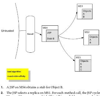
3.1.3.2.1 Determining Potential Socket Usage Each WebLogic Server instance can potentially open a socket for every other server instance in the cluster. However, the actual maximum number of sockets used at a given time depends on the configuration of your cluster. In practice, clustered systems generally do not open a socket for every other server instance, because objects are deployed homogeneously—to each server instance in the cluster.
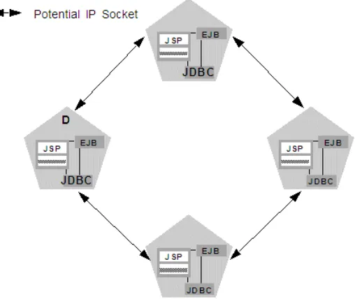
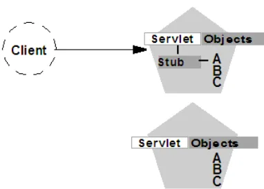
If your cluster uses in-memory HTTP session state replication, and you deploy objects homogeneously, each server instance potentially opens a maximum of only two sockets, as shown in Figure 3–2.
Figure 3–2 Homogeneous Deployment Minimizes Socket Requirements
WebLogic Server Communication In a Cluster
The two sockets in this example are used to replicate HTTP session states between primary and secondary server instances. Sockets are not required for accessing clustered objects, due to the collocation optimizations that WebLogic Server uses to access those objects. (These optimizations are described in Section 5.2.6, "Optimization for Collocated Objects.") In this configuration, the default socket reader thread
configuration is sufficient.
Deployment of "pinned" services—services that are active on only one server instance at a time—can increase socket usage, because server instances may need to open additional sockets to access the pinned object. (This potential can only be released if a remote server instance actually accesses the pinned object.) Figure 3–3 shows the potential effect of deploying a non-clustered RMI object to Server A.
Figure 3–3 Non-Clustered Objects Increase Potential Socket Requirements
In this example, each server instance can potentially open a maximum of three sockets at a given time, to accommodate HTTP session state replication and to access the pinned RMI object on Server A.
3.1.4 Client Communication via Sockets
Clients of a cluster use the Java implementation of socket reader threads.
WebLogic Server allows you to configure server affinity load balancing algorithms that reduce the number of IP sockets opened by a Java client application. A client accessing multiple objects on a server instance will use a single socket. If an object fails, the client will failover to a server instance to which it already has an open socket, if possible. In older version of WebLogic Server, under some circumstances, a client might open a socket to each server instance in a cluster.
For best performance, configure enough socket reader threads in the Java Virtual Machine (JVM) that runs the client. For instructions, see Section 10.2.18.1.3, "Set the Number of Reader Threads on Client Machines."
3.2 Cluster-Wide JNDI Naming Service
Clients of a non-clustered WebLogic Server server instance access objects and services by using a JNDI-compliant naming service. The JNDI naming service contains a list of the public services that the server instance offers, organized in a tree structure. A WebLogic Server instance offers a new service by binding into the JNDI tree a name that represents the service. Clients obtain the service by connecting to the server instance and looking up the bound name of the service.
Server instances in a cluster utilize a cluster-wide JNDI tree. A cluster-wide JNDI tree is similar to a single server instance JNDI tree, insofar as the tree contains a list of available services. In addition to storing the names of local services, however, the cluster-wide JNDI tree stores the services offered by clustered objects (EJBs and RMI classes) from other server instances in the cluster.
Each WebLogic Server instance in a cluster creates and maintains a local copy of the logical cluster-wide JNDI tree. The follow sections describe how the cluster-wide JNDI tree is maintained, and how to avoid naming conflicts that can occur in a clustered environment.
3.2.1 How WebLogic Server Creates the Cluster-Wide JNDI Tree
Each WebLogic Server in a cluster builds and maintains its own local copy of the cluster-wide JNDI tree, which lists the services offered by all members of the cluster. Creation of a cluster-wide JNDI tree begins with the local JNDI tree bindings of each server instance. As a server instance boots (or as new services are dynamically deployed to a running server instance), the server instance first binds the
implementations of those services to the local JNDI tree. The implementation is bound into the JNDI tree only if no other service of the same name exists.
Once the server instance successfully binds a service into the local JNDI tree,
additional steps are performed for clustered objects that use replica-aware stubs. After binding the clustered object's implementation into the local JNDI tree, the server instance sends the object's stub to other members of the cluster. Other members of the cluster monitor the multicast or unicast address to detect when remote server
instances offer new services.
Caution: Do not use the cluster-wide JNDI tree as a persistence or caching mechanism for application data. Although WebLogic Server replicates a clustered server instance's JNDI entries to other server instances in the cluster, those entries are removed from the cluster if the original instance fails. Also, storing large objects within the JNDI tree can overload multicast or unicast traffic and interfere with the normal operation of a cluster.
Note: When you start a Managed Server in a cluster, the server instance identifies other running server instances in the cluster by listening for heartbeats, after a warm-up period specified by the
Cluster-Wide JNDI Naming Service
Figure 3–4 shows a snapshot of the JNDI binding process.
Figure 3–4 Server A Binds an Object in its JNDI Tree, then Unicasts Object Availability
In the previous figure, Server A has successfully bound an implementation of clustered Object X into its local JNDI tree. Because Object X is clustered, it offers this service to all other members of the cluster. Server C is still in the process of binding an implementation of Object X.
Other server instances in the cluster listening to the multicast or unicast address note that Server A offers a new service for clustered object, X. These server instances update their local JNDI trees to include the new service.
Updating the local JNDI bindings occurs in one of two ways:
■ If the clustered service is not yet bound in the local JNDI tree, the server instance
binds a new replica-aware stub into the local tree that indicates the availability of Object X on Server A. Servers B and D would update their local JNDI trees in this manner, because the clustered object is not yet deployed on those server instances.
■ If the server instance already has a binding for the cluster-aware service, it updates
its local JNDI tree to indicate that a replica of the service is also available on Server A. Server C would update its JNDI tree in this manner, because it will already have a binding for the clustered Object X.
In this manner, each server instance in the cluster creates its own copy of a
Figure 3–5 Each Server's JNDI Tree is the Same after Unicast Messages are Received
3.2.2 How JNDI Naming Conflicts Occur
Simple JNDI naming conflicts occur when a server instance attempts to bind a non-clustered service that uses the same name as a non-clustered service already bound in the JNDI tree. Cluster-level JNDI conflicts occur when a server instance attempts to bind a clustered object that uses the name of a non-clustered object already bound in the JNDI tree.
WebLogic Server detects simple naming conflicts (of non-clustered services) when those services are bound to the local JNDI tree. Cluster-level JNDI conflicts may occur when new services are advertised over multicast or unicast. For example, if you deploy a pinned RMI object on one server instance in the cluster, you cannot deploy a replica-aware version of the same object on another server instance.
If two server instances in a cluster attempt to bind different clustered objects using the same name, both will succeed in binding the object locally. However, each server instance will refuse to bind the other server instance's replica-aware stub in to the JNDI tree, due to the JNDI naming conflict. A conflict of this type would remain until one of the two server instances was shut down, or until one of the server instances undeployed the clustered object. This same conflict could also occur if both server instances attempt to deploy a pinned object with the same name.
3.2.2.1 Deploy Homogeneously to Avoid Cluster-Level JNDI Conflicts
To avoid cluster-level JNDI conflicts, you must homogeneously deploy all
replica-aware objects to all WebLogic Server instances in a cluster. Having unbalanced deployments across WebLogic Server instances increases the chance of JNDI naming conflicts during startup or redeployment. It can also lead to unbalanced processing loads in the cluster.
If you must pin specific RMI objects or EJBs to individual server instances, do not replicate the object's bindings across the cluster.
Note: In an actual cluster, Object X would be deployed
Cluster-Wide JNDI Naming Service
3.2.3 How WebLogic Server Updates the JNDI Tree
When a clustered object is removed (undeployed from a server instance), updates to the JNDI tree are handled similarly to the updates performed when new services are added. The server instance on which the service was undeployed broadcasts a
message indicating that it no longer provides the service. Again, other server instances in the cluster that observe the multicast or unicast message update their local copies of the JNDI tree to indicate that the service is no longer available on the server instance that undeployed the object.
Once the client has obtained a replica-aware stub, the server instances in the cluster may continue adding and removing host servers for the clustered objects. As the information in the JNDI tree changes, the client's stub may also be updated.
Subsequent RMI requests contain update information as necessary to ensure that the client stub remains up-to-date.
3.2.4 Client Interaction with the Cluster-Wide JNDI Tree
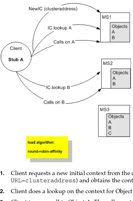
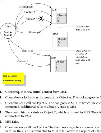
Clients that connect to a WebLogic Server cluster and look up a clustered object obtain a replica-aware stub for the object. This stub contains the list of available server instances that host implementations of the object. The stub also contains the load balancing logic for distributing the load among its host servers.
For more information about replica-aware stubs for EJBs and RMI classes, see
Section 6.3, "Replication and Failover for EJBs and RMIs."
4
4
Understanding Cluster Configuration
This following sections explain how the information that defines the configuration of a cluster is stored and maintained, and the methods you can use to accomplish
configuration tasks:
■ Section 4.1, "Cluster Configuration and config.xml" ■ Section 4.2, "Role of the Administration Server" ■ Section 4.3, "How Dynamic Configuration Works"
■ Section 4.4, "Application Deployment for Clustered Configurations" ■ Section 4.5, "Methods of Configuring Clusters"
4.1 Cluster Configuration and config.xml
The config.xml file is an XML document that describes the configuration of a WebLogic Server domain. config.xml consists of a series of XML elements. The Domain element is the top-level element, and all elements in the Domain descend from the Domain element. The Domain element includes child elements, such as the Server, Cluster, and Application elements. These child elements may have children of their own. For example, the Server element includes the child elements WebServer, SSL and Log. The Application element includes the child elements EJBComponent and WebAppComponent.
Each element has one or more configurable attributes. An attribute defined in
config.dtd has a corresponding attribute in the configuration API. For example, the Server element has a ListenPort attribute, and likewise, the
weblogic.management.configuration.ServerMBean has a ListenPort
attribute. Configurable attributes are readable and writable, that is, ServerMBean has a getListenPort and a setListenPort method.
To learn more about config.xml, see "Domain Configuration Files" in Understanding Domain Configuration for Oracle WebLogic Server.
4.2 Role of the Administration Server
A domain can include multiple WebLogic Server clusters and non-clustered WebLogic Server instances. Strictly speaking, a domain could consist of only one WebLogic Server instance—however, in that case that sole server instance would be an Administration Server, because each domain must have exactly one Administration Server.
There are a variety of ways to invoke the services of the Administration Server to accomplish configuration tasks, as described in Section 4.5, "Methods of Configuring Clusters." Whichever method you use, the Administration Server for a cluster must be running when you modify the configuration.
When the Administration Server starts, it loads the config.xml for the domain. It looks for config.xml in the directory:
MW_HOME/user_projects/domains/domain_name/config
where domain_name is a domain-specific directory, with the same name as the domain.
Each time the Administration Server starts successfully, a backup configuration file named config.xml.booted is created in the domain directory. In the unlikely event that the config.xml file should be corrupted during the lifetime of the server
instance, it is possible to revert to this previous configuration.
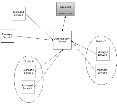
Figure 4–1 shows a typical production environment that contains an Administration Server and multiple WebLogic Servers instances. When you start the server instances in such a domain, the Administration Server is started first. As each additional server instance is started, it contacts the Administration Server for its configuration
How Dynamic Configuration Works
Figure 4–1 WebLogic Server Configuration
4.2.1 What Happens if the Administration Server Fails?
The failure of an Administration Server for a domain does not affect the operation of Managed Servers in the domain. If an Administration Server for a domain becomes unavailable while the server instances it manages—clustered or otherwise—are up and running, those Managed Servers continue to run. If the domain contains clustered server instances, the load balancing and failover capabilities supported by the domain configuration remain available, even if the Administration Server fails.
For instructions on re-starting an Administration Server, see "Avoiding and Recovering from Server Failure" in Managing Server Startup and Shutdown for Oracle WebLogic Server.