CR-Form-v3
CHANGE REQUEST
WCS CR ?
rev-
Current version: 1.1 corr. 2For HELP on using this form, see bottom of this page or look at the pop-up text over the symbols.
Proposed change affects: AS Imp Spec X Best Practices Paper Other
Title: WCS change request - Improve CRS descriptions
Source: Arliss Whiteside, WCS 1.2 SWG
Work item code: Date: 2008-12-02
2008-08-19
Category: D
Use one of the following categories: F (Critical correction)
A (corresponds to a correction in an earlier release) B (Addition of feature),
C (Functional modification of feature) D (Editorial modification)
Reason for change: The current text describing CRSs and BoundingBoxes, in WCS 1.1 Corrigendum 2 [OGC 07-067r5], is still not clear enough.
Summary of change: Improve text describing CRSs and BoundingBoxes, in Subclauses 7.5 and 7.6 of WCS 1.1 Corrigendum 2, based on discussions in the WCS 1.2 SWG.
Consequences if not approved:
Clauses affected: 7.5, 7.6, 10.3.6
Other specs Other core specifications Affected: Abstract specifications
Best Practices Papers
Supporting Doc.
Other comments: Status Disposition
Edit Subclauses 7.5 and 7.6 as follows:
7.5 CRS definitions and references
7.5.1 WCS use of CRSs
WCS operation requests and responses frequently include references to a defined Coordinate Reference System (CRS), and sometimes include a CRS definition. A defined CRS is required for spatial referencing by coordinates, and is a coordinate system which is related to an object by a datum. This specification makes use of material in several other OGC documents that specify how to define and reference CRSs.
In many cases, WCS operation requests and responses transfer only references to defined CRSs, not the actual CRS definitions. Each referenced CRS shall be defined somewhere, but that definition may not be electronically accessible or encoded in XML. Nonetheless, the referenced definitions often need to be used by WCS server software. In this case, the server software may either encode the CRS definition within that software or reference the CRS definition stored elsewhere.
7.5.2 CRS definitions
OGC Abstract Specification Topic 2 “Geographic information — Spatial referencing by coordinates” [OGC 0508-103015], which contains ISO/DIS 19111:2007, specifies how to define many types of CRSs, including the Datums and Coordinate Systems that define a each
CRS. Clause 7 of tThat document specifies the following types of CRSs, all of which might be used with a WCS grid coverage:
a) GeodeticCRS (formerly GeographicCRS and GeocentricCRS) – Acoordinate reference system based on a geodetic datum describing the relationship of a two- or
coordinate system, in which position is specified by geodetic latitude, geodetic
longitude and (in the three-dimensional case) ellipsoidal height. A geocentric CRS uses a 3D Cartesian or a spherical coordinate system.
b) ProjectedCRS – Atwo-dimensionalcoordinate reference system derived from a base 2D geographic CRS by applying a coordinate conversion known as a map projection to latitude and longitude ellipsoidal coordinate values.
c) VerticalCRS – A one-dimensional coordinate reference system based on a vertical datum describing the relation of gravity-related heights or depths to the Earth.
d) CompoundCRS – Acoordinate reference system combining a non-repeating sequence of at least two independent coordinate reference systems.
e) ImageCRS – A coordinate reference system based on an image datumwhich defines the relationship of a coordinate system to an image.
f) DerivedCRS – A coordinate reference system which is defined by applying a
coordinate conversion to another coordinate reference system. (A derived CRS inherits its datum from its base CRS)
g) EngineeringCRS – Acoordinate reference system based on an engineering datum which defines the relationship of a coordinate system to a local reference.
NOTE Clauses 4 and 7 of [OGC 08-015] provide more complete definitions of these types of CRSs and of many terms used in these definitions.
Clause 12 of GML 3.1.1 [OGC 03-105r1] specifies how to XML encode the definitions of all these types of CRSs, based on an older version of OGC Abstract Specification Topic 2 [OGC 04-046r3]. Three GML 3.1.1 profiles extract the parts of GML 3.1.1 that appear useful to a WCS, namely:
a) OGC 05-094r1, GML 3.1.1 CRS support profile, which is used by the following two profiles
b) OGC 05-095r1, GML 3.1.1 common CRSs profile, which covers GeographicCRS, ProjectedCRS, VerticalCRS, and CompoundCRS definitions
c) OGC 05-096r1, GML 3.1.1 grid CRSs profile, which covers ImageCRS and DerivedCRS definitions
Annex F in this document specifies how to XML encode a GridCRS definition, in a simplified manner that is loosely based on a DerivedCRS.
7.5.3 CRS references
Clause 10.3 of OWS Common [OGC 06-121r3] specifies how that CRSs shall be referenced
using either a URL or URN. A URL can may be used to reference a definition that is available using this URL. When not in the same XML document, those definitions shall be electronically available using this URL. Alternately, a URN in the “ogc” URN namespace can may be used, and often should be used, to reference a CRS definition identified in that “ogc” URN
The format of URNs in the “ogc” namespace is recommended in Clause 7 of OGC Best Practices Paper [OGC 06-02307-092r1], “Definition identifier URNs in OGC namespace”.
Some recommended URN formats include some “parameter” values that allow that URN to be used for an entire family of CRSs (such as different origins).
Numerous specific URN values for CRSs and components are currently specified in:
a) Clause 8 and Annex A of [OGC 06-02307-092r1], “Definition identifier URNs in OGC namespace”, for numerous CRSs and components
h) Clause 10 of OGC 05-096r1, GML 3.1.1 grid CRSs profile, for ImageCRSs, DerivedCRSs, and components (including URNs for most many possible 2D ImageCRSs)
NOTE OGC 05-096r1 does not mention that the image identifiers used in these ImageCRSs must be unique in the “ogc” URN namespace.
i) Subclause F.3 in this document, for three specific OperationMethods (expected to be referenced by most 2D GridCRS definitions)
7.5.4 Definition of ImageCRS
The definition and meaning of an ImageCRS is currently described in multiple documents, which are often not clear to readers. The basic definition of an ImageCRS is specified in Clauses 8.3 (Table 13), 9.4 (Tables 32, 18, and 17), 10.3 (Tables 39, 40, and 33), and B.3.5 of OGC Abstract Specification Topic 2 “Geographic information — Spatial referencing by
coordinates” [OGC 08-015], including two approved change requests OGC 08-010r1 and
08-089r4.
Summarizing the Topic 2 [OGC 08-015 as corrected] definition of an ImageCRS:
a) A single coordinate reference system (SingleCRS) is comprised of (and defined by) one coordinate system and one datum (see Figure 2).
Figure 1 — Conceptual model of a coordinate reference system
calculated from geometric elements such as distances and angles and vice versa. The coordinate system definition includes the dimension of the coordinate space, the names, the units of measure, the directions and sequence of the axes. One coordinate system may be used by multiple coordinate reference systems.
NOTE 1 A coordinate system is spatial, not spatial-temporal.
k) A datum specifies the relationship of a coordinate system to an object, thus creating a coordinate reference system. A Datum defines the position of the origin, the scale, and the orientation of a coordinate system. For geodetic and vertical coordinate reference systems, the datum shall relate the coordinate system to the Earth. For other types of coordinate reference systems, the datum may relate the coordinate system to another physical or virtual object. A datum thus ensures that the abstract mathematical concept “coordinate system” can be applied to the practical problem of describing positions of points on the object by means of coordinates.
NOTE 2 For an ImageCRS, the “physical or virtual object” is the specific image and the scene captured in that image.
l) An image coordinate reference system (ImageCRS) is a coordinate reference system based on an image datum, which combines an ImageCS with an ImageDatum. Image coordinate reference systems are treated as a separate sub-type of CRS because the definition of the associated Image Datum contains additional attributes not relevant to other datums.
NOTE 3 Topic 2 describes an image datum as “For an image datum, the anchor is usually either the centre of the image or the corner of the image, as indicated by the anchorDefinition.” The URNs specified in OGC 05-096r1 restrict the anchor to the first corner of the image, as discussed below.
NOTE 4 A CRS for an image with both spatial and temporal axes can be defined as a CompoundCRS, as defined in OGC Abstract Specification Topic 2. However, no examples of such a CRS are now included in this document.
m) An image coordinate system (ImageCS) is a coordinate system used by an Image CRS. It shall be either an affine coordinate system or a Cartesian coordinate system.
NOTE 5 The OGC does not now use an affine coordinate system for images, since we have not yet found a use for this.
NOTE 6 The term “image grid” is often used in other standards to describe the concept of Image CRS or CS. However, care has to be taken to correctly interpret this term in the context in which it is used. The term “grid cell” is often used as a substitute for the term “pixel”, but that is not correct based on ISO 19123.
n) A CartesianCS is a two- or three-dimensional coordinate system with orthogonal straight axes. In the 2D case, both axes shall have the same length unit; in the 3D case, all axes shall have the same length unit. A CartesianCS shall have two or three axis associations; the number of associations shall equal the dimension of the CS.
o) An image pixel (coverage) grid is defined as the set of lines with constant integer coordinate values. Each pixel is centred at a grid point, which is the corner of (up to) four coverage grid cells.
p) An image datum (ImageDatum) defines the origin of an image coordinate reference system, and thus the origin of the ImageCS in a specific ImageCRS. For an image datum, the anchor is usually the first corner of the image, as indicated by the
anchorDefinition. Image datums include an implication that the coordinate system is in the image plane. They define the origin of the coordinate system within this image plane.
NOTE 8 The image datum definition applies regardless of whether or not the image is georeferenced. Georeferencing is performed through a coordinate transformation between the ImageCRS and a geodetic or projected CRS. The transformation plays no part in the image datum definition, but the specific ImageCRS is referenced by that transformation. On the other hand, the location of the image datum within the image affects the correct values of some Transformation parameters.
NOTE 9 Topic 2 states “An image datum defines the origin of an image coordinate reference system, and is used in a local context only.” It is clear this means that an image datum defines the position in the image of the origin of the associated image coordinate system. It is not clear what is meant by “used in a local context only”. We interpret this to mean for a specific image, so the ImageDatum and the ImageCRS must be different for each specific image.
NOTE 10 Topic 2 states “For an image datum, the anchor is usually either the centre of the image or the corner of the image, as indicated by the anchorDefinition.” The URNs specified in OGC 05-096r1 restrict the anchor to the first corner of the image, as discussed below.
q) The origin of the image pixel (coverage) grid is at an image pixel identified by the anchorDefinition in the ImageDatum. The exact origin of the Image CS may be associated in two ways with a pixel or grid. In the most frequent case, the grid is associated with the pixel data in such a way that the grid lines run through the centres of the pixels, producing grid points at the centres of the pixels. The grid points and (recorded) pixels will thus have integer coordinate values. The image coordinate system origin is then the anchorDefinition grid point recorded for that image, at the position of that recorded image pixel (coverage range) value. (In this case, the attribute “pixel in cell” will have the value “cell corner”.)
NOTE 11 Alternatively, the exact origin of the image coordinate system may be defined such that the grid lines are associated with “pixel corners” rather than the coverage grid cell corners. In this case, the extent of each pixel value is crudely approximated by a cell that is offset from the coverage grid cells, so that the pixel cell corners lie at the centres of these offset grid cells. The grid cell corners and pixel locations will thus have non-integer coordinate values, the fractional parts always being 0,5. The image coordinate system origin is then the centre of the grid cell whose inside corner is the anchorDefinition grid point recorded for that image, with this corner at position of the anchorDefinition recorded image pixel (coverage range) value. The attribute “pixel in cell” will now have the value “cell centre”. This difference in perspective has no effect on the image interpretation, but is important for correct values of parameters used by the coordinate
transformations using coordinates in this defined image CRS.
r) An image datum contains a pixelInCell UML attribute with the type PixelinCell. That attribute specifies the way the image coverage grid is associated with the image data coverage range (pixel) values. As specified in ISO 19123, grid coverage range (or image pixel) values are for the grid points, which are at the corners of coverage grid cells.
The use of a different ImageCRS definition and identifier for each image is counter-intuitive to some people. The needed uses of a different ImageCRS (definition) identifier for each image include:
a) The ImageCRS identifier will often be used to find the correct georeferencing
transformation for an image, or to confirm that the correct transformation was found or retrieved. (This is one reason why the ImageCRS identifier is required to be included in the transformation definition.)
b) The ImageCRS identifier may be used to find the corresponding image pixel values. This might be done by attaching the ImageCRS identifier to the corresponding image pixel values.
c) The ImageCRS identifier must be used as the correct CRS for image point positions that are input to and then transformed by the georeferencing transformation, or for image point positions that are transformed by and then output from the georeferencing transformation.
d) The ImageCRS identifier must be used as the correct CRS for point positions measured in an (unrectified) image.
NOTE 13 In all these uses, the ImageCRS identifier can and should be used considering that identifier to be opaque. In item b) above, if the identifier URN is not considered opaque, the image identifier could be extracted and used to find the corresponding image pixel values.
NOTE 14 The georeferencing transformation does NOT use the ImageCRS identifier when performing a transformation! By definition, a Topic 2 / ISO 19111 transformation is allowed to use only the parameter values included in that transformation definition, with the equations and any (default) parameter values provided by the "formula" or "formulaCitation".
7.5.5 ImageCRSs used in WCS
WCS 1.1 uses the specialized form of ImageCRSs specified in the GML 3.1.1 grid CRSs profile [OGC 05-096r1 with Corrigendum 1 OGC 111 and Corrigendum 2 OGC 06-146]. Each coordinate value in an ImageCRS is the index of a spatial position in the image, with units of Grid Spacings, see Subclause 10.9 of [OGC 05-096r1]. To refer to the exact position of a recorded pixel value, each coordinate value will be have an integer value. However, to refer to a general position in an image, each coordinate value may also include a fractional value to reference positions between recorded pixels.
NOTE 1 An ImageCRS is defined in OGC Abstract Specification Topic 2, which includes a copy of ISO 19111. That ImageCRS is specialized in the GML 3.1.1 grid CRSs profile. Such an ImageCRS has only spatial coordinate axes. A CRS for an image with both spatial and temporal axes can be defined as a CompoundCRS, as defined in OGC Abstract Specification Topic 2. However, no examples of this are now included in this document.
WCS 1.1 uses only ImageCRSs with the origin at the centre of the first a recorded pixel, to be consistent with ISO 19123. WCS 1.1 also uses only ImageCRSs with the origin at the first pixel, in order to use the URNs specified in OGC 05-096r1. Negative coordinate values shall not be used, since they would reference pixels that do not exist.
here and in [OGC 05-096r1] instead of “lower left” (or “top left” or other terms) pixel, in the absence of universally understood definitions of “lower left” and “top left”. (The terms “LowerCorner” and “UpperCorner” are defined and used only in bounding boxes, not in images or other grid coverages.)
When the origin pixel of a WCS output coverage is different than the origin pixel of the offered coverage, then the output coverage’s ImageCRS shall be changed to an ImageCRS with a different identifier or to a GridCRS.Therefore, the ImageCRS identifier should be changed when the origin pixel is changed, from the origin of an offered coverage to the origin of an output coverage that is derived from that offered coverage.
NOTE 2 One possible way to generate a different ImageCRS Identifier for an output image that has a different origin than the offered coverage would be to extend the ImageCRS Identifier of the offered
coverage. This extension could encode the position of the output image’s origin pixel, relative to the offered image’s origin pixel. This relative origin identifier could contain one (positive) integer for each dimension of the ImageCRS. For example, if the offered coverage's ImageCRS is has the URL
"urn:ogc:def:crs:OGC:0.0:ImageCRSpixelCenter:ABC123", the output coverage's ImageCRS might be "urn:ogc:def:crs:OGC:0.0:ImageCRSpixelCenter:ABC123DE:987:654”, if that URN is unique.
Wheneversuch an ImageCRS is referenced, the first recorded pixel shall be the first pixel in this ImageCRS. For a spatial 2D image, the first recorded pixel has the indices 0,0. For a spatial 3D image, the first recorded pixel has the indices 0,0,0. For a spatial 1D image, the first recorded pixel has the index 0.
In WCS 1.1, all 2D ImageCRSs should are be referenced using the URN form specified in Subclause 10.2 of [OGC 05-096r1], namely
“urn:ogc:def:crs:OGC:0.0:ImageCRSpixelCenter:TBD”. Each specific ImageCRS shall be for the image, or image group, whose alphanumeric character string identifier is substituted for the “TBD” in this URN. When these URNs are used, there is no need to provide a definition for each specific ImageCRS, since the definition of this ImageCRS is completely specified in Clause 10 of [OGC 05-096r1], with the exception of the image identifier that is directly included in this URN.
NOTE 3 In all cases, an ImageCRS applies to a single image. This is because the ImageCRS datum is (normally) the first pixel of that image, which is spatial-temporally different for each image. However, two or more ImageCRSs will sometimes be equivalent for many purposes, when multiple images are taken by the same camera from the same camera position with the same camera orientation directions. In that case, an equivalent ImageCRS might be used instead of the correct ImageCRS.
7.5.56 GridCRSs used in WCS
WCS 1.1 uses the GridCRSs specified in Annex F of this document. Each coordinate value in a GridCRS is the index of a spatial position in the grid coverage, with units of Grid Spacings (like an ImageCRS). (Coordinate values in a GridCRS are NOT in the referenced GridBaseCRS.) To refer to a recorded pixel, each coordinate value will be an integer. However, to refer to a general position in a grid coverage, each coordinate value may also
include a fractional value to reference positions between recorded pixels.
The origin of a GridCRS may be located at either of the followingtwo alternatives:
a) The origin may be the first pixel recorded for that grid coverage (similar to an
be changed when its first pixel is changed, from the origin of an offered coverage to the origin of an output coverage that is derived from that offered coverage. SpecificallyIn addition, the GridOrigin value(s) should shall be changed.
b) The origin may be located at any grid point in the specified grid. In this case, negative and positive coordinate index values may be used, since they reference pixel positions that are defined, but may not be recorded in the grid coverage. In this case, the
GridCRS origin pixel (with 0 valued indices) may be anywhere in the pixels recorded, or may be anywhere outside the pixels recorded, and thus not recorded. In both cases, the same GridCRS definition may be used for grid coverages recorded with different first pixels, from the same or different original coverages or images. When any part of the GridCRS definition is changed, such as the GridOrigin, GridOffsets, or
GridBaseCRS, Also, the GridCRS definition identifier should shall be changed when any other part of the GridCRS definition is changed, either the GridOrigin, GridOffsets, or GridBaseCRS.
NOTE 1 A coverage encoding format extension may specify that only one of these alternatives may be used with that encoding format.
In WCS 1.1, the definition of each referenced GridCRS used is always included in the same operation request or response.
NOTE 2 That is, a GridCRS definition is never referenced in WCS 1.1 (outside the same operation request or response). This is doneGrid CRS definitions are always included since many most GridCRSs will be unique. No URN form for referencing GridCRSs is currently now specified, but probably shouldmight be defined in the future. Such a GridCRS may could then be referenced as a SupportedCRS or in a
BoundingBox, included in an operation request or response.
7.5.67 WCS use of GridCRSs
In WCS 1.1, a georectified image or grid coverage always uses a GridCRS, for both offered and output coverages. Each GridCRS specifies the origin and the offsets between recorded
coverage pixels, in the referenced GridBaseCRS. For a georectified image or coverage, the referenced GridBaseCRS shall be a ground space CRS, which may be a GeographicCRS, ProjectedCRS, VerticalCRS, or CompoundCRS that combines a VerticalCRS with a 2D GeographicCRS or ProjectedCRS.
NOTE 1 An ImageCRS is not used for a georectified image because a GridCRS provides more useful information. Specifically, that GridCRS specifies the locations of the grid points in the referenced
GridBaseCRS, and that information is often needed to usefully exploit this coverage. If used, an ImageCRS
reference URN would provide only the identification of the image, thus allowing finding the image pixels. However, an ImageCRS requires that the origin be the first pixel recorded. Furthermore, an ImageCRS should only be used for an image, not for a more general grid coverage.
In WCS 1.1, an unrectified image may shall use either an ImageCRS or a GridCRS with its GridBaseCRS being an ImageCRS, for both offered and output coverages. Such a GridCRS
may should be used when an unrectified image was previously processed, to change the pixel spacing or origin. That GridCRS specifies the origin and offsets between the recorded coverage pixels, each in the referenced original ImageCRS before the known previous processing. If such previous processing is not known, an ImageCRS for the current
NOTE 2 A separate ImageCRS is not used provided for an unrectified image when a GridCRS is known and used, because that GridCRS allows providing more useful information. Also,using providing an ImageCRS separate from the GridBaseCRS of that GridCRS would not provide needed additional information. The only information in anWCS 1.1 ImageCRS reference URN is the identification of the image, allowing finding the image pixels. For an offered coverage, that image identification is not needed separate from the Identifier in the CoverageDescription. For If an ImageCRS is assigned to an output coverage, that the image identification identifier for that ImageCRS should is not be assigned by the WCS
clientserver.
When an unrectified image uses a GridCRS with its GridBaseCRS being an ImageCRS, that ImageCRS should may be referenced using a URN, and no separate ImageCRS definition is required or supported by WCS 1.1. The GridOrigin and GridOffsets parameters specify the pixel positions in this GridCRS relative to the referenced
ImageCRS. For example, these parameters can specify different pixel spacings and origin, of the GridCRS relative to the referenced original ImageCRS (before known previous processing). If no previous processing is known, a GridCRS may be used with GridOrigin values of zero, and GridOffsets values that specify the same pixel spacings.
In WCS 1.1, no a GridCRS should shall not be used whose GridBaseCRS is another GridCRS, for either a georectified or unrectified image.A new GridCRS may use the same GridBaseCRS as another GridCRS, with different grid point spacings or origin.
NOTE 3 This limitation is partially because WCS 1.1 provides no place to transfer the definition of a GridCRS that is used as the GridBaseCRS of another GridCRS which is for an offered image. A URL to a location where the GridCRS definition is stored might be used, except for difficulties in implementing such URL access.
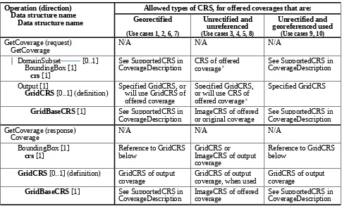
7.5.78 Current WCS uses of CRSs
WCS 1.1 operationrequests and responses frequently include references to a defined Coordinate Reference System (CRS), and sometimes include a CRS definition. Table 1 summarizes these CRS uses in this version of this OGC Standard. In Table 1:
a) In the left column, all the WCS 1.1 data structures and parameters that define or reference CRSs are listed in Bold. All of these are CRS references (with type URI) except for GridCRS (three times), which are GridCRS definitions.
b) In the left column, indented lists are used to identify which larger data structures and operation request or response contains each listed CRS reference or definition. The multiplicity of most data structures and parameters is indicated using UML notation. c) In the other three columns, the allowed types of CRSs are listed for each CRS reference
or definition, for each of three conditions based on the nature of the offered coverage. These conditions map to the use cases described in Annex G and listed in the table header.
d) In the second column, the allowed types of CRSs are listed for a (previously) georectified offered coverage.
requested to apply, or cannot apply, the (known) georeferencing coordnate transformation.
f) In the right column, the allowed types of CRSs are listed for an unrectified offered coverage that is georeferenced when the georeferencing coordinate transformation IS used by the GetCoverage operation to georectify that image. If the unrectified coverage is georeferenced but the georeferencing coordinate transformation is NOT used by the GetCoverage operation to georectify that image, then the third column applies except for including the georeferencing coordinate transformation with the output coverage.
Table 1 — WCS uses of CRSs
Operation (direction) Data structure name
Data structure name
Allowed types of CRS, for offered coverages that are: Georectified
CoverageDescription CRS of offered coverage a See SupportedCRS in CoverageDescription
Output [1]
GridCRS [0..1] (definition) Specified GridCRS, orwill use GridCRS of offered coverage
Specified GridCRS, or will use CRS of offered coverage a
Specified GridCRS
GridBaseCRS [1] See SupportedCRS in
CoverageDescription ImageCRS of offered or original coverage See SupportedCRS in CoverageDescription GetCoverage (response)
Coverage N/A N/A N/A
BoundingBox [1]
crs [1] Reference to GridCRSbelow GridCRS or ImageCRS of output coverage
Reference to GridCRS below
GridCRS [0..1] (definition) GridCRS of output
coverage GridCRS of output coverage, when used GridCRS of output coverage
GridBaseCRS [1] See SupportedCRS in
Operation (direction) Data structure name
Data structure name
Allowed types of CRS, for offered coverages that are: Georectified
GridCRS [0..1] (definition) GridCRS of offered
coverage GridCRS of offered coverage, if used GridCRS of offered coverage, if used
GridBaseCRS [1] See SupportedCRS in
CoverageDescription ImageCRS ImageCRS
ImageCRS [0..1] (none) ImageCRS of offered
coverage, if used ImageCRS of offered coverage, if used GetCapabilities (response)
SupportedCRS [0..*] See SupportedCRS in CoverageDescription
a The CRS of an unrectified offered coverage may be an ImageCRS or a GridCRS with a GridBaseCRS that is an ImageCRS. b In addition to a GeographicCRS or ProjectedCRS, other ground space CRSs may be referenced, including a VerticalCRS or a CompoundCRS that combines a VerticalCRS with a 2D GeographicCRS or ProjectedCRS. These CRS types are sometimes referred to as ground CRSs.
c An ImageCRS for an unrectified offered image shall be listed as a SupportedCRS, so that it may be referenced as the GridBaseCRS of a GridCRS. This ImageCRS shall be the ImageCRS of that unrectified offered image, or the ImageCRS that is referenced as the
GridBaseCRS of the GridCRS that is used by that unrectified offered image.
d Followed by zero or more of any SupportedCRS listed in the CoverageDescription.
7.6 BoundingBox use in WCS
7.6.1 General terms
This specification uses the BoundingBox and WGS84BoundingBox data structures, specified in Subclause 10.2 of OWS Common [OGC 06-121r3], to express the minimum rectangular bounding region around (available or requested) coverage data. In a Bounding Box data structure, the LowerCorner defines the edges of the (available or requested) region in the directions of decreasing coordinate values in a CRS (normally the algebraic minimum
coordinates), and the UpperCorner defines the edges in the directions of increasing coordinate values in that CRS (usually the algebraic maximum coordinates).
NOTE 1 The directions of decreasing coordinate values are usually the algebraic minimum coordinates, and the directions of increasing coordinate value are usually the algebraic maximum coordinates. This is always the case when the CRS is an ImageCRS or GridCRS. (For an ImageCRS or GridCRS, the “first pixel” is at the LowerCorner of the BoundingBox using that CRS.) The exception is when the BoundingBox spans the
For continuous (interpolatable) offered grid coverages, thesecorner coordinate values shall be
computed determined from the areas of all the (available or requested) coverage grid cells with all four corners at recorded grid points. For output grid coverages, the corner coordinate values shall be determined from the areas of all the coverage grid cells with all four corners at desired output grid points.
NOTE 12 Inclusion of the areas of all grid cells is not necessarily the same as inclusion of all the grid points, when the grid coverage spans the antimeridian as discussed below.
In keeping with ISO 19123, WCS 1.1 considers only grids whose points lie at the corners (not the centres) of the grid cells. This document thus primarily considers discusses “continuous” grid coverages, not “discrete” grid coverages, as those terms are defined in ISO 19123.
However, many “discrete” grid coverages can also be handled, by not allowing any interpolation.
NOTE 3 We have not yet analyzed whether all “discrete” grid coverages can be handled by WCS 1.1, or only those “discrete” grid coverages which meet some conditions.
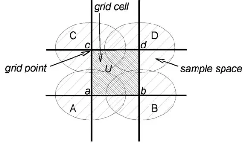
As illustrated in Figure 2 below, grid points (a, b, c, d) define a grid cell (U) and are surrounded by "sample spaces" (A, B, C, D) as those terms are used in Subclause 8.2.2 of ISO 19123.
Figure 2 — Grid points, grid cells, and sample spaces
NOTE 23 For these sample spaces, this document avoids using terms such as “sample grid” or “pixels”, although such terms are often used elsewhere.
The following subclauses clarify the use of such a bounding box near discontinuities in a geographic CRS, and the handling of grid points at the edges of the coverage.
7.6.2 Spanning the antimeridian of a geographic CRS
A Bounding Box defined in a geographic CRS (or a WGS84BoundingBox) whose LowerCorner longitude is greater than that of its UpperCorner shall describe a region that crosses the longitude discontinuity.
EXAMPLE A bounding region encompassing the Pacific Ocean could be described by a BoundingBox with a positive LowerCorner longitude and a negative UpperCorner longitude.
NOTE 1 Users and implementers may avoid using the above “extended” interpretation of the Bounding Box by
EITHER (a) using a CRS whose value discontinuity lies outside the minimum bounding region (e.g., a geographic CRS with a different prime meridian), when such a CRS exists.; OR (b) treating longitude as unbounded but periodic (using the XML Schema strings “-INF” and “INF” to denote negative and positive infinity). (See also Subclause 10.2.5 of OWS Common [OGC 06-121r3].)
NOTE 2 It is not possible to include the North or South Pole (or either end of the antimeridian) in a bounding box when a geographic CRS is used. In order to include the North or South Pole in a bounding box, another type of CRS must be used.
If the data represented by the coverage is intended to be continuous (or interpolatable) across the antimeridian, then a server should perform spatial interpolation near and across the
antimeridian just as it does elsewhere.
7.6.3 Treatment of edge grid points
The spatial extent of a grid coverage extends only as far as the outermost grid points contained in the bounding box. It does NOT include any area (partial or whole grid cells or sample spaces) beyond those grid points.
NOTE This bounding box is NOT the extent sometimes considered, which also includes rectangular sample spaces (pixels) centrered on the outermost grid points – as indicated in Subclause 7.3.3 6 of WMS 1.3 [OGC 04-042]. Such pixel extents are often poor approximations of the sensor physics / grid data collection process. EXAMPLE The extent of a global data set in WGS84 geographic decimal degrees with a grid spacing of 1.0 degree might be expressed as a WGS84BoundingBox with LowerCorner and UpperCorner longitudes of
(respectively) -179.5 and +179.5, or -179.0 and +180.0, when that data set is not considered continuous (interpolatable) across the antimeridian at 180 degrees.
If the data represented by a coverage is intended to be continuous (and interpolatable) across the antimeridian, then a WCS server shall perform spatial interpolation near and across the antimeridian just as it does elsewhere. When that a global data set is intended to be
interpolatable across the antimeridian, the LowerCorner and UpperCorner longitudes
(respectively) might may be --180 and +180 degrees (with redundant first and last columns of data), or –INF and INF.