THE INFLUENCE OF THE IN SITU CAMERA CALIBRATION FOR DIRECT
GEOREFERENCING OF AERIAL IMAGERY
E. Mitishita * R. Barrios, J. Centeno
Department of Geomatics - Federal University of Parana, UFPR - Centro Politécnico - Setor de Ciências da Terra CEP 81531-990 - Curitiba, Paraná, Brazil –[email protected]; [email protected];[email protected]
Commission I/3
KEY WORDS: Direct Georeferencing, GNSS, INS, In Situ Calibration, Photogrammetry
ABSTRACT
The direct determination of exterior orientation parameters (EOPs) of aerial images via GNSS/INS technologies is an essential prerequisite in photogrammetric mapping nowadays. Although direct sensor orientation technologies provide a high degree of automation in the process due to the GNSS/INS technologies, the accuracies of the obtained results depend on the quality of a group of parameters that models accurately the conditions of the system at the moment the job is performed. One sub-group of parameters (lever arm offsets and boresight misalignments) models the position and orientation of the sensors with respect to the IMU body frame due to the impossibility of having all sensors on the same position and orientation in the airborne platform. Another sub-group of parameters models the internal characteristics of the sensor (IOP). A system calibration procedure has been recommended by worldwide studies to obtain accurate parameters (mounting and sensor characteristics) for applications of the direct sensor orientation. Commonly, mounting and sensor characteristics are not stable; they can vary in different flight conditions. The system calibration requires a geometric arrangement of the flight and/or control points to decouple correlated parameters, which are not available in the conventional photogrammetric flight. Considering this difficulty, this study investigates the feasibility of the in situ camera calibration to improve the accuracy of the direct georeferencing of aerial images. The camera calibration uses a minimum image block, extracted from the conventional photogrammetric flight, and control point arrangement. A digital Vexcel UltraCam XP camera connected to POS AV TM system was used to get two photogrammetric image blocks. The blocks have different flight directions and opposite flight line. In situ calibration procedures to compute different sets of IOPs are performed and their results are analyzed and used in photogrammetric experiments. The IOPs from the in situ camera calibration improve significantly the accuracies of the direct georeferencing. The obtained results from the experiments are shown and discussed.
1. INTRODUCTION
The determination of the exterior orientation parameters (EOP) of an imaging sensor is an indispensable requirement to extract geoinformation from imagery. Aerial triangulation (AT), direct sensor orientation (DG) and integrated sensor orientation (ISO) are the main approaches used today to achieve EOPs for photogrammetric applications. Basically, aerial triangulation determines simultaneously the EOPs of a block of images and object space coordinates of tie points using a set of ground control points (GCP) and the well know bundle adjustment; In the Direct Georeferecing the EOP are determined directly by the integration of differential global positioning system (DGPS) with inertial measurement unit (IMU) and the Integrated Sensor Orientation combines the direct exterior orientation data with the traditional bundle adjustment to perform simultaneous determination. The advantages and disadvantages are well studied and discussed in many research articles (e.g. Heipke et al., 2002; Cramer & Stallmann, 2002; Ip et al., 2007).
The reliability of the interior orientation parameters (IOP) of the imaging sensor is an important requirement for the three approaches. However, in aerial triangulation the coordinates of tie points are computed in the same reference system of the control points, like in an interpolation procedure (Heipke et al., 2002); having the point intersections fixed in the object space, the small inaccuracies in the interior orientation parameters are compensated by some exterior orientation parameters due to
high correlation with some IOP. On the other hand, in the Direct Georeferencing, as it happens in extrapolation from the projection center to the object space, the whole solution is rigorous and it is not able to compensate the inaccuracies of the parameters (Jacobsen and Wegmann, 2002). In addition, as the IMU cannot be placed at the projection centre of the imaging sensor, the Direct Georeferencing requires six extra parameters related to sensors mounting (the offsets of the IMU relative to the projection centre and the angles of boresigth misalignment between the IMU and the image coordinate system) (Yastikli and Jacobsen, 2005).
According to Kersting (2011), to simultaneously estimate the mounting parameters, the principal point coordinates and the focal length by system calibration, a special photogrammetric block is required. The optimum flight configuration consists of four strips which are captured from two flying heights in opposite directions with 100% side overlap, and two strips, which are flown in the same direction with the least possible side overlap (while having proper tying among the images from the two flight lines). Other block configurations are proposed according to the types of parameters involved in the calibration. However, to obtain a minimum block configuration that allows a reliably parameters estimation in the same project job, an
extra flight mission and resources would be necessary, in
general. To overcome the resources limitations to perform the in-site system calibration, different solutions are proposed to improve the accuracy of the direct georeferencing, such as:
Integrated Sensor Orientation (Heipke et al., 2002) and
refinement of a small set of system calibration parameters via
the in-site self-calibration (Cramer and Stallman, 2002).
This paper shows the initial results of the study that was conducted to analyse the performance of the IOP refinements via in-situ self-calibration to increase the accuracy of the direct georeferencing. Two small sub blocks within the whole block
are extracted to perform the IOP refinements. The new set of
interior orientation parameters are used to check the accuracy of
the direct georeferencing for a single model. The test models are
within the whole block but they aren’t inside of the small blocks used for IOP refinements.
The following three sections contain information about the photogrammetric block used in this study, methodology to perform the IOP refinements, the obtained results from the performed experiments and discussed, as well as the conclusions and recommendations for future work.
2. MATERIAL AND METHODS
2.1 Imaging sensor
Images were obtained using a digital large format frame camera UltraCamXp. The source image has 17310 pixels cross track and 11310 pixels along track. The physical pixel size is equal to 6 microns. The calibrated focal length is equal to 100.500 mm ± 0.002 mm. Principal point coordinates (xo = -0.120 mm ± 0.002 mm and yo= 0.0 mm ± 0.002 mm). The remaining lens distortion is less than 0.002 mm. The IMU equipment connected to the camera is the Applanix POSTrack AV 510 IMU. The IMU absolute accuracies (RMS) – Position < 0.1 m; Roll and Pitch < 0.005 deg; Yaw < 0.008 deg.
2.2 Block of images
The whole block has approximately 70 images in 6 strips. The strips were flown in following directions: two in N-S, one in S-N, two in E-W and one in W-E. Each strip has about 12 images, acquired with nearly 80% forward overlap. The lateral overlap between strips is close to 60%. The flight height was approximately 2500 m. The ground sample distance (GSD) for this flight height is close to 0.15 m. The project area has 30 signalized control points. The three-dimensional coordinates of the 30 points were acquired by precise differential GNSS survey. The root mean square error (RMSE) values for the X, Y and Z coordinates were approximately 2 cm.
2.3 Method
The proposed methodology considers that the new IOP values can model a parcel of inaccuracies of the direct determination of the EOP and the displacement of the colinearity condition due to the high correlation among parameters in the bundle adjustment; the new set of IOP can be used to improve the quality of direct georeferencing. Considering this supposition, the traditional in-situ self-calibration of the imaging sensor using the physical model as proposed by Brown, (1971) is utilized to compute a new set of the Interior Orientation Parameters. To perform this procedure, two small conventional sub-blocks of images are extracted from the whole block. The exterior orientation parameters of the images from the direct georeferencing are included in the bundle adjustment as additional observations by weight constraint. The EOP values are weighted according to the nominal accuracies. A conventional set of tie points and only one control point, located in the center of the block, are added in process. The obtained
3.1 In situ self calibration
To undertake a study with different flight directions, two sub perform the measurements via a semi-automatic procedure. The bundle adjustment self-calibration for both blocks was performed using the following conditions: Only one control point in the center of block; the images EOP from direct measurement were introduced in the bundle adjustment as additional observations. The following precisions were considered for the measurements: 0.003 millimeters (half of pixel) for x and y image coordinates; two centimeters for 3D coordinates of the control point (from the GNSS surveying); For the EOPs, 10 centimeters for positions and 30 seconds for orientations (nominal values) were assumed. The main results from the two self-calibration bundle adjustments are shown in Tables 1 and 2.
IOPs FROM THE TWO SELF- CALIBRATIONS
Experi-ment
c xp yp k1
σc (mm) σp (mm) σyp(mm) σk1 (mm-2) First
Block
100.534 -0.118 -0.005 -2.3695 e-8
0.005 0.002 0.002 5.1808 e-9
Second Block
100.529 -0.118 -0.004 -3.0340 e-8 0.004 0.001 0.001 4.3032 e-9 c= Focal length; (xp, yp)= Coordinates of principal point;
k1= Radial lens distortion; (σ)= Standard deviation.
Albeit the residuals in the direct measurements of EOP from the two bundle adjustment are acceptable, the obtained results should be better analyzed and discussed. The residuals of the coordinates of the positions of the camera stations are three times smaller than the a-priori adopted precision, as it can be seen in Figures 4 and 5.This results were expected, due to the direct correlations among parameters (c – Zs; xp– Xs; yp–Ys). These correlations allow that the parameters related to focal length and coordinates of principal point can absorb some inaccuracies connected to the direct determination of the Xs, YS and Zs (coordinates of the camera position). Considering what was aforementioned and comparing the nominal value of IOP to the new values, reported in Table 1, it can be observed that the focal length changed its value significantly. Biases in the lever-arm offsets and atmospheric variations might have also contributed to variations in the principal distance and the principal point coordinates. However, such a large variation observed in the principal distance was not expected. For instance, the impact of a variation of 0.030 mm in the focal length on the object space (image scale of the blocks) would be equivalent to 75 cm in de Zs coordinates. An error in the vertical component of the lever arm offset of such magnitude is quite unlikely to happen since an accurate conventional field survey has been performed to determine the lever arm offsets. Analyses to detect the causes of this significant variation in focal length are out of this study.
RESIDUALS ANALYSIS RMSE of the Residuals in
image coordinates (microns)
Residuals in control point coordinates
(millimeters)
RMSE of the residuals in EOPs (centimeters and
seconds)
x y X Y Z Xs Ys Zs ω φ χ
First 1 1 -2 2 0 3 3 3 14 11 40
Second 1 1 -3 3 0 3 3 2 22 18 14
Maximum residuals
First 7 6 -2 2 0 5 6 7 25 18 54
Second 6 7 -4 4 0 7 8 5 36 22 29
Rmse = Root mean square error
In relation to the exterior orientation measurements, the interior orientation parameters, used as additional parameters in collinearity equations, are not directly correlated among the rotation angles (ω, φ, χ). Unlike the residuals of the coordinates of the camera stations that were three times smaller than the nominal precisions, the residuals in direct measurements of the rotation angles are approximately equal to a-priori adopted precisions, as seen in Table 2, Figures 3 and 4. Additionally, the angular residuals in omega and phi (ω, φ) show systematic effects that were modeled by refinements of the angular values. These effects may be related to the boresight misalignment (the angular difference between the IMU and imaging sensor). Different precisions are found in the angular measurements in the two bundle adjustments performed. In the second block the angular adjustments in ω and φ are bigger than the second, as displayed in the results reported in Table 2, Figures 3 and 4. The lower precisions of angular measurements in the second block may justify less accuracy in 3D point determination, as shown in the analysis of the check point discrepancies reported in Table 3. Although the first block holds greater residuals in kappa (χ), their distribution does not describe a systematic effect as shown in the Figure 3. The analysis of the check point discrepancies, reported in Table 3, confirm that the values of kappa did not affect the accuracy of 3D point determination in
the first block. More details about the strips’ acquisitions and the direct measurements of the images’ EOP that may justify the different precisions for the two blocks, so far, unknown.
CHECK POINTS DISCREPANCIES
DX DY DH DZ
First Block
µ -3.0 4.2 13.3 5.0
RMSE 10.3 11.1 15.1 11.8
Max 20.9 27.5 33.3 24.0
Second Block
µ -5.3 1.0 21.3 2.7
RMSE 23.0 9.5 24.8 12.6
Max 44.2 21.2 47.0 35.3
µ = Mean values of the discrepancies (cm)
RMSE = Root mean square error of the discrepancies (cm) Max= Maximum discrepancy (cm)
DH = Horizontal discrepancy
One control point located in the center of the block is used in the two performed self-calibration. The values of the residuals its coordinates are approximately equal in both performed experiments. All the remaining control points were used as check points.
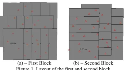
(a) – First Block (b) – Second Block Figure 1. Layout of the first and second block
Table 1. The interior orientation parameters (IOP) and its precisions estimated in the two self-calibrations
Table 2. Main results of the residuals analysis of the two self-calibration bundle adjustment using first and second block
A closer look at Table 1 and Figure 2 reveals a slight variation in the k1 (coefficient of the radial lens distortion), estimated in the two self-calibration experiments. However, the image distortions were increased considering that the image has maximum distortion below two microns (nominal information). This increment of the image distortion may be related to the effect of the atmospheric refraction in the aerial images. Photogrammetric refraction and radial lens distortion are correlated effects in the image formation (Andrade, 1977).
3.2 Direct georeferencing of single models
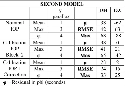
Two models that are close but not included in the two self-calibration blocks were used to derive 3D object space coordinates via single photogrammetric intersection using direct determination of the position and orientation of the imaging sensor. First, the models were oriented by indirect georeferencing using control points to obtain the 3D coordinates of a set of photogrammetric points well distributed in the model (close to the “Von Gruber locations”). These points are used as check points to evaluate the quality of photogrammetric intersection using direct measurements. Three experiments were conducted for each model. The first used the nominal IOP; the second used the IOP from the performed self-calibrations experiments. In the third experiment, the systematic tendencies of the orientation angles (ω, φ) were corrected using the root mean square errors (RMSE) of the residuals computed from the systematic residuals of the self-calibration experiments. The model uses the geometric information from the self-calibration performed with the block that has images with same flight directions. For instance, becausethe images of the first model were flown in direction W-E, then the IOP and RMSE from the first block was used. The second model used IOP and RMSE
Figure 4. Shows the obtained residuals in EOPs from the bundle adjustment in the first block
Figure 5. Shows the obtained residuals in EOPs from the bundle adjustment in the second block Figure 2. Profiles of the radial lens distortion that were
Both models have 4 control points to perform the indirect georeferencing processes. Eighteen photogrammetric points are defined in each model, resulting 22 photogrammetric points in the model to be used as check points. To perform the process the photogrammetric intersection, the direct measurement of EOP were fixed by weight constraint using 1 millimeter for positions and 1 second for orientations and the value of 0.003 millimeters (half of pixel) is considered for the precision for x and y image coordinates. The main obtained experiments of 3D photogrammetric intersections are improved significantly when the IOP from the in situ calibration are used. However to achieve accuracies close to those that were obtained in the in situ self-calibration blocks the direct measurement of the orientation parameters should be refined by the RMSE of the angular tendencies that were computed in each block. Using this procedure, the first model with images that were flown in W-E direction yielded better accuracies than the second model. The horizontal and vertical accuracies that were achieved in the first and second models are similar to those accuracies obtained in self-calibration
blocks that provided the new IOP and RMSE for angular corrections.
As mentioned before, due to the direct correlation between parameters, the inaccuracies of the sensor position can be modeled by focal distance and coordinates of principal point. However, only the new IOP from the in-situ self calibration were not able to model the inaccuracies of the direct measurements of the position and orientation of the imaging sensor due to the absence of direct correlation between some IOP and rotation angles (ω, φ, χ).
The methodology used to refine the values of the orientation angles,obtained by direct measurement, and IOP improves the horizontal and vertical accuracies of the 3D point determination in photogrammetric intersection. However, two important questions emerge here. 1) Will the behavior of the angular residuals be similar for other photogrammetric block appointing a systematic tendency? 2) How far can the model be away from the small block used in-situ self calibration process? Further investigations will answer these questions.
4. CONCLUSION AND RECOMMENDATIONS FOR FUTURE WORK
This paper shows the results of an empiric study that was performed to increase the accuracies of the direct georeferencing of single photogrammetric model using the refinements of the interior orientation parameters via in situ self-calibration. To perform the study, two small images blocks with different strips flight directions were extracted from the whole photogrammetric block. In the first block, the strips were flown in directions W-E and E-W and the second in N-S and S-N. Using the direct measurement of the images’ EOP and only one control point, located in the center of the block, the in situ self-calibration was performed for both blocks. Angular tendencies were detected by analysis of residuals from the self-calibration bundle adjustment. These values with new values of IOP were used to perform the direct georeferencing of single photogrammetric model. From the results of the performed experiments, the main conclusions are drawn:
- Using the direct georeferencing of a single photogrammetric model, the vertical and horizontal accuracies of the 3D point intersection are improved significantly when the new values of IOP from the in situ calibration are used. However the accuracies are lower than from those that were obtained in situ self-calibration processes;
- To achieve accuracies approximately equal to those that were obtained in the in situ self-calibration blocks, the direct measurement of the orientation parameters should be refined by the RMSE of angular tendencies that were computed in each block; - Due to the direct correlation between parameters (c – Zs; xp – Xs; yp –Ys), the inaccuracies of the sensor position can be modeled by focal distance and coordinates of principal point. However, only the new values of IOP from the in-situ self calibration were not able to model the inaccuracies of the direct measurements of imaging sensor orientation due to the absence of direct correlation between some IOP and rotation angles (ω, φ, χ);
Table 4. Shows the main results of the analysis performed to verify the performance of 3D photogrammetric point intersection for the first model using direct measurement of EOP.
- The methodology used to refine the values of the orientation angles, obtained by direct measurement, and IOP, improves the horizontal and vertical accuracies of the 3D point determination in photogrammetric intersection. However, further investigations, using other block dimension and model configurations, must be performed to confirm the proposed methodology.
Future works will focus on performing more experiments of the in situ self-calibration using image blocks with different dimensions and strips configurations. The experiments will be conducted to investigate the viability of the the proposed methodology for refinements of IOP and images’ orientation parameters.
ACKNOWLEDGMENTS
We would like to thank the two Brazilian governmental agencies CNPq (The National Council for Scientific and Technologic Development) and CAPES (The Coordinating Agency for Advanced Training of High-Level Personnel) for their financial support of this research and TOPOCART (Surveying Engineering and Aero Mapping Company) to provide the necessaries material to develop this study.
REFERENCES
A.IP ,N.EL-SHEIMY AND M.MOSTAFA,2007. Performance analysis of integrated sensor orientation, Photogrammetric Eng. Remote Sens., vol. 73, no. 1, 89-97.
ANDRADE, B.,1977. Photogrammetric Refraction. Ph.D. dissertation, The Ohio State University, 117 p.
BROWN, D., 1971. Close range camera calibration, Photogrammetric Engineering, 37(8), 855–866.
Cramer,M. AND STALLMANN,D.,2002. System Calibration for Direct Georeferencing, International Archives of Photogrammetry, Remote Sensing and Spatial Information Sciences, 34(3/A), 79–84.
JACOBSEN, K., 2000. Combined Bundle Block Adjustment versus Sensor Orientation, ASPRS Annual Convention 2000, Washington D.C.
JACOBSEN, K., WEGMANN, H., 2002. Dependencies and problems of Direct Sensor Orientation. “Integrated Sensor Orientation”, Integrated Sensor Orientation, Test Report and Workshop Proceedings (C. Heipke, K. Jacobsen, and H. Wegmann, editors), OEEPE Official Publication No. 43, 73– 84.
HEIPKE,C.,K.JACOBSEN, AND H.WEGMANN,2002. Analysis of the Results of the OEEPE Test “Integrated Sensor Orientation”, Integrated Sensor Orientation, Test Report and Workshop Proceedings (C. Heipke, K. Jacobsen, and H. Wegmann, editors), OEEPE Official Publication No. 43, 31– 49.
HONKAVAARA, E., ILVES, R., JAAKKOLA, J.,2003. Practical Results of GPS/IMU/camera System Calibration. In: Proc. Of Workshop: Theory, Technology and Realities of Inertial/GPS/Sensor Orientation, ISPRS WG I/5, Barcelona, CD-ROM, 10 p.
KERSTING, A. P., 2011. Quality Assurance of Multi-Sensor Systems, PhD Thesis, University of Calgary, Department Of Geomatics Engineering, Calgary, Canada, 265 pages.
WEGMANN,H.,2002. Image Orientation by Combined (A)AT with GPS and IMU. In: Proceedings of ISPRS Commission I Mid-term Symposium, Nov. 2002, Denver, Colorado, USA.