AN OVERVIEW OF IN-ORBIT RADIOMETRIC CALIBRATION OF
TYPICAL SATELLITE SENSORS
Guoqing Zhou* , Chenyang Li, Tao Yue, Linjun Jiang, Na Liu, Yue Sun, Mingyan Li
Guangxi Key Laboratory for Spatial Information and Geomatics Engineering, Guilin University of Technology, Guilin, Guangxi, 541004, China, [email protected]
Commission VI, WG VI/4
KEY WORDS: overview, in-orbit radiometric calibration, typical satellite sensors, visible/near-infrared bands, thermal infrared band, lamp calibration, solar radiation-based calibration, blackbody-based calibration
ABSTRACT:
This paper reviews the development of in-orbit radiometric calibration methods in the past 40 years. It summarizes the development of in-orbit radiometric calibration technology of typical satellite sensors in the visible/near-infrared bands and the thermal infrared band. Focuses on the visible/near-infrared bands radiometric calibration method including: Lamp calibration and solar radiation-based calibration. Summarizes the calibration technology of Landsat series satellite sensors including MSS, TM, ETM+, OLI, TIRS; SPOT series satellite sensors including HRV, HRS. In addition to the above sensors, there are also summarizing ALI which was equipped on EO-1, IRMSS which was equipped on CBERS series satellite. Comparing the in-orbit radiometric calibration technology of different periods but the same type satellite sensors analyzes the similarities and differences of calibration technology. Meanwhile summarizes the in-orbit radiometric calibration technology in the same periods but different country satellite sensors advantages and disadvantages of calibration technology.
* Corresponding author: Guoqing Zhou; Tel. /Fax: +86(773)5896073;
E-mail: [email protected].
1. INTRODUCTION
During the remote sensing imaging process, the influence of atmospheric factors, temperature and outer space radiation would bring changes to the imaging spectrometer performance. In order to ensure the accuracy of satellite imaging in-orbit calibration is needed. The main purpose of absolute radiometric calibration is to determine the exact quantitative relationship between the entrance pupil radiation values for each channel of the sensor and the DN (digital number) value obtained by the imaging system. Over the past 40 years, rapid developments of satellites, sensor technology have made. Those satellites equipped with imaging sensors almost cover all the areas such as land satellites, oceanic satellites, environmental satellites, meteorological satellites, high spatial resolution commercial satellites, hyperspectral satellites and SRA satellites. The radiometric calibration system is usually containing: vacuum equipment; solar calibration device such as solar diffuse or the stimulation lamp equipment (visible/near infrared bands calibration); blackbody and temperature monitoring instruments (thermal infrared bands calibration). This paper summarizes the development of in-orbit radiometric calibration technology of typical satellite sensors in the visible/near-infrared bands and the thermal infrared band.
2. OVERVIEW OF THE TECHNOLOGY OF IN-ORBIT RADIOMETRIC CALIBRATION
2.1 Lamp Calibration
Some sensors carrying standard lamp to complete calibration task include in-orbit spectral calibration and in-orbit relative radiometric calibration in the visible and near-infrared bands.
The major radiation source of those sensors is standard lamp. In the early days, most sensors used the method— “lamp + diffuse”, such as CZCS and TM of Landsat-5. By using standard lamp, the diffuse plate with known reflectivity changed the irradiance values to radiance values. The disadvantage of this method was that it couldn’t complete full-aperture and full-field calibration. Therefore, majority of sensors turned to use another more advanced method— “lamp + integrating sphere”, such as ALI of EO-1, CCD camera of CBERS-1,2 and HRV1/2 of SPOT-2 (Fox N P, 2002a).
The following points should be considered in designing standard lamp:
1. The optical system of the device and the mechanical of the device are stability enough to withstand high pressure during process of launch.
2. In deep space environment working for a long time the calibrator can always remain stable status.
3. Small size and low power consumption.
The advantages of lamp calibration are easy to operate but this method also has disadvantages:
1. Only a portion of the optical element can be calibrated and the entire optical path cannot be calibrated. When the optical components which are not calibrated have been attenuated, will be mistaken for the ground targets radiance changes, consequently the calibration results cannot truly reflect the changes in the optical system.
2. There has a large difference between the spectral distribution of standard lamp and solar spectral distribution. Using the standard lamp as the calibration source obtained the results should to be further corrected the spectral matching, increasing the uncertainty of calibration. The International Archives of the Photogrammetry, Remote Sensing and Spatial Information Sciences, Volume XL-7/W4, 2015
3. The lamp which is installed on the satellite will be attenuated, bringing the uncertainty of calibration, impact using the calibration results.
2.1.1. Landsat/TM: Landsat-4 satellite was launched on 1982 by USA. It equipped with the Thematic Mapper (TM). Compared with the MSS, TM has a lot of improvement in many aspects one of them is equipped with a lamp device.
2.1.2. IRS-P3/MOS: IRS-P3 remote sensing satellite was launched on March 1996 by Indian. It equipped with MOS using two CMH8/60 lamps as the calibration light source one of them is the main calibration source and the other one is used to compare their performance (Figure 1). Calibration lamps are arranged in four voltage levels and to be illuminated by the voltage level sequentially in the calibration process.
Figure 1. lamp calibrator of MOS (MMERMANN G. et al,1993a)
2.1.3. SPOT-4/HRVIR and VEGETATION: SPOT-4 was launched on March 1998 by France. The payload of SPOT-4 is HRVIR and VEGETATION. The lamp calibration system of HRVIR can provide complete lighting to the imaging system. Its main role is to monitor the stability and sensitivity of the detector and camera. The in-orbit calibration system of VEGETATION consists of a lamp and relative optical device, which mounted on a carbon fiber rods, can be moved in front of the optical system. Each of four cameras has about 100 detectors and can be illuminated simultaneously. Scanning the entire field of view by rotating the carbon fiber rods ensure coverage the entire detector. The entire calibration process takes about three minutes, once a month. The standard lamp of VEGETATION has good performance and can be used to monitor the sensitivity of the camera.
2.1.4. Landsat-7/8/ETM+/OLI: Landsat-7 ETM+ (1999) and Landsat-8 OLI (2013) also have lamp device.
OLI has two stimulation lamp devices which installed in the telescope aperture stop. The stimulation lamp is equipped with six small lamps which consist of integrating hemisphere. They can be irradiated to the focal plane of the OLI. The stimulation lamp of OLI will turn on once a week to monitor the OLI radiation stability.
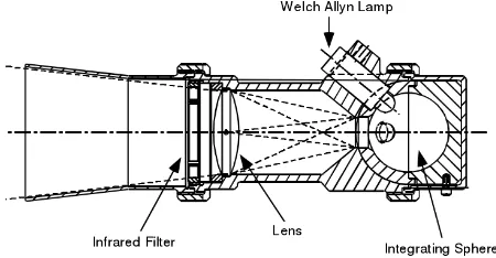
2.1.5. EO-1/ALI: Earth Observing-1 was launched on 2000 by USA. It equipped with the sensor named ALI. The major radiation source is standard lamp (Figure 2). Its radiation calibration system consists of three Welch Allyn inflatable lamp and a integrating sphere which diameter is 0.8in. Calibration lamps are arranged in three voltage levels and can provide three radiometric calibration data in a calibration process and can reach 2% accuracy of absolute radiometric calibration.
Figure 2. EO-1 ALI internal calibration source (J.A. Mendenhall, 1999a)
2.2 Solar radiation-based Calibration
In remote sensors practical working, the radiation energy of each channel is a value which comes the effect of absorption, reflection, scattering of the solar radiation through the ground and atmospheric. Hence, choosing the solar as the in-orbit radiation calibration source can’t let the sensor to be irradiated by the solar directly. It will not only make the measurable value can’t consist with the actual value but also damage the spectral imager itself.
To solve this problem, it need attenuates the direct solar radiation through the relevant device (such as diffusion plate), so that the solar radiation can be reduced in appropriate range. The requirements of remote sensor solar radiation calibrator are:
1. Can receive solar radiation throughout the year; 2. After receiving solar radiation in different radiation angles output the same radiance, calibrator has stable working conditions in long term;
3. Solar radiation can achieve full aperture and full field-of-view to obtain of radiation, all pixels of the probe can obtain uniform illumination.
4. After direct solar radiation is attenuated by diffusing plate or other solar calibration attenuator, the in-orbit solar calibrator's radiance will be similar with the ground target radiance.
5. The working hours of in-orbit solar calibration should to be chosen in the time when the atmosphere under the subpoint is the Earth's shaded area. The solar can just irradiate into the solar calibrator and reduce the effect of the signal between the atmosphere and the ground targets. To solve the above problems, after extensive research for domestic and overseas scholars, they put forward to use PTFE-covered diffusing plate as the solar calibrator. The advantage of using diffuse can make multiple reflections of the incident light in a few microns depth of material surface, the emergent light almost completely random distribution. Hence, the diffusing plate has a good Lambertian characteristic. When a large area of PTFE-covered diffusing plate to be used in sensor, it can complete the absolute calibration requirement for full aperture and full field-of-view.
The following points should be considered in the course of using diffusing plate:
1. The material of diffusing plate should to close the ideal Lambertian characteristic, anti-radiation, stable and able to ensure has uniform distribution for the spectral reflectance in a large area.
2. In outer space, the Lambertian characteristic of the diffusing plate can be attenuated with the effect of UV radiation and high-energy particle bombardment. For this problem researchers designed a device which can detect the change including the radiance, the reflectance and the The International Archives of the Photogrammetry, Remote Sensing and Spatial Information Sciences, Volume XL-7/W4, 2015
solar constant, to ensure if the condition is not satisfied, the diffuse will be blocked by the above device, doesn’t enter the working state.
3. The spectral distribution of solar is most similarity with the spectral distribution of target objects.
Solar radiation-based calibration is the main in-orbit calibration method in visible and near infrared bands. The main error of solar radiation-based calibration include a lot of destabilizing factors ,such as the stability of the solar radiation and the diffusion plate reflectivity, especially diffuser plate stability, the intense ultraviolet radiation and spacecraft contamination will change the diffuse reflectance, it will become the instability during a long-term solar radiation-based calibration.
Solar radiation-based calibration including: 1. The error of calibration principle; 2. The error of atmospheric scattering; 3. The error of atmospheric stability;
4. The error of diffuse reflectance and the BRDF correction values
The main error source of solar calibration: the instability of solar simulator spectral radiance; optics efficiency of collimator; the gain instability of scanner sub-system; channel noise and quantization error. Usually the total absolute error cannot exceed 6.7%.
2.2.1. Landsat Series Satellites:Landsat series satellites, as the earlier developed land-surface observation satellites, plays a leading role in calibration technology. Landsat1-5 (1972-1984) satellites were equipped with MSS. Landsat1-3 were the first generation of land-surface observation satellites of USA. The earliest satellite was installed with solar calibration device but had no radiation attenuation device. It was equipped with a small aperture, thus it was easily blocked by dust. Its calibration device exposed to the space environment and with no effective shield caused quick decay of its performance. The gray value quantization level of MSS was 6bit.
Landsat-4 (1982.7.16) and Landsat-5 (1984.3.1) were the second generation of land-surface observation satellites equipped with thematc mapper (TM). The gray value quantization level of TM was 8bit. Solar calibrator of TM is showed in Figure 3.
Figure 3. Solar calibrator of TM (Barsi J R, 2003a)
Landsat-7 (1999.4.15) was the third-generation of Landsat series satellite, almost the same period with the launch of SPOT-4 (1998.3.24) satellite. ETM+ (Figure 4) first made the calibration algorithms public, improved the performance of the algorithm and software and was equipped with IAS system (Brian L.Markham, 2012a). There were two kinds of solar calibrators: full aperture solar calibrator (FASC) and partial aperture solar calibrator (PASC). FASC was made of PTFE. Its gray value quantization level was 9bit (8bit transmiited). Radiometric calibration error was less than 5% after the performance was improved. The instability of ETM + calibration results can’t exceed 0.5% each year.
Figure 4. Configuration of ETM+ (http://directory.eoportal.org/)
Landsat-8 (2013.2.11) satellite, the most advanced new-generation land satellite by far. It was equipped with the Operational Land Imager (OLI) (Figure 5) and Thermal Infrared Remote Sensor (TIRS) (Figure 6). Both of the two were push-broom sensors and their gray value quantization was 12bit (Geilman D I, 1993a) and (Patrice Henry, 2001a). The uncertainty of OLI radiometric calibration was less than 3% (D.P.Roy, 2014a).
Figure 5. Configuration of OLI (D.P.Roy, 2014a)
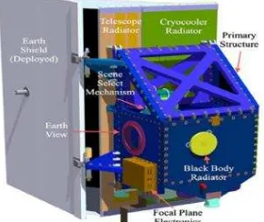
Figure 6. Configuration of TIRS (D.P.Roy, 2014a)
2.2.2. Nimbus-7 satellite /TOMS: Nimbus-7 satellite was launched on October 1978, compared to the first generation land-surface observation satellites Landsat-3(1978.3.5), a few months later. It is equipped with the total ozone mapping spectrometer (TOMS) which is installed solar calibrator. In order to attenuate solar radiation, TOMS was installed three aluminum diffusion plates, one is used to attenuate solar radiation, one as a reference plate is used to monitor the reflect performance of the reflection plate, another one is used to block The International Archives of the Photogrammetry, Remote Sensing and Spatial Information Sciences, Volume XL-7/W4, 2015
the calibration device to preventing contamination and attenuation. The calibration device also installed a diffuse reflectance measuring apparatus. It is composed of diffuser and mercury fluorescent lamp.
To prevent satellite's gas impacts the diffusion plate performance, the device is equipped with a heating mantle in outside, when the satellite through the Arctic, the disc will rotate through the corresponding electric device, so that the sensor can do the calibration.
2.2.3. SPOT Series of Satellite:The first-generation of French SPOT series of satellite (SPOT-1) was launched on February 22, 1986, almost the same period as the Landsat-5 (1984.3.1). The first-generation SPOT satellites were equipped with line array push-broom scanner—HRV. HRV had two types of cameras: one was multi-spectral and the other was the panchromatic. The two types of cameras had different pixel numbers, different spatial resolution and corresponding different gray quantized values. One was 8bit and the other was 6bit. The calibration technology of HRV was more mature than the MSS and TM. And its camera mirror can rotate 180° and then could block the main optical path of calibration device. Thus, it could complete the calibration mission both during the day and night.
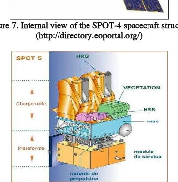
The French SPOT series of satellites launched the second generation satellite SPOT-4 (Figure 7) on March 24, 1998. SPOT-4 was equipped with HRVIR and VEGETATION (VGT). HRVIR was equipped with optical fiber device which was mounted on the outer surface of the HRVIR to ensure that solar radiation can be received at any times. It could obtain a known irradiance value at each observation time. The gray value quantization level of HRVIR was 8bit. VEGETATION was equipped with carbon fiber rods in front of the optical system. The fiber rods could scan the entire field of view by rotating. Complete an integral calibration test of each month. Its gray value quantization level was 10bit (James R. Irons, 2012a). SPOT-5 (2002.5.4) architecture is showed in Figure 8.
Figure 7. Internal view of the SPOT-4 spacecraft structure (http://directory.eoportal.org/)
Figure 8. Schematic view of the SPOT-5 architecture (http://directory.eoportal.org/)
2.2.4. CBERS-1/ IRMSS :CBERS-1 was launched on October 14, 1999. The main payload of CBERS-1 was IRMSS which was the first sensor using the solar calibration technology in China (Mingli GU, 2002a). IRMSS uses wide-field optical system. The main components of the solar calibration include a shutter, anti-irradiation window, enters the objective lens group, the field lens, uniform light modulator, the exit lens and the exit mirror. It uses the integrating sphere as the absorbed light device and uses PTFE as the coating material. The shutter and mirror are mounted in entrance, only turned on when calibrates the sensor, they are turned off in rest of the time, thus reduces the instrument performance degradation.
2.2.5. Terra and Aqua/MODIS:MODIS was the leader of satellite-borne sensors in the same period. So far its influence in the field of remote sensing was still obvious. Both the Terra satellite and Aqua satellite all mounted MODIS. Terra was launched on December 18, 1999, almost the same period as the Landsat-7 (1999.4.15). Aqua was launched on May 2, 2002, almost the same period as the SPOT-5 (2002.5.3). Diffuse plate of Terra and Aqua were used Spectralon and had good Lambertian characteristic to achieve full aperture solar calibration. MODIS was installed with Solar Diffuser Stability Monitor (SDSM). The method of solar calibration of MODIS was named Level 1B. MODIS uses Solar Diffuser (SD), Solar Diffuser Stability Monitor (SDSM) and Spectral Radiometric Calibration Assembly (SRCA) to complete in-orbit radiometric calibration. The gray value quantization level of MODIS was 12bit (Xiong X, 2007a). MODIS scan cavity and on-board calibrators is showed in Figure 9.
Figure 9. MODIS scan cavity and on-board calibrators (Xiong X, 2006a)
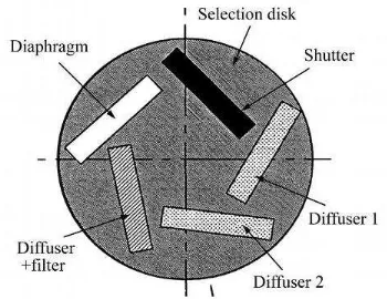
2.2.6. ENVISAT-1(ESA)/MERIS: ENVISAT-1 satellite was launched on March 1, 2002 by ESA. It equipped with the Moderate Resolution Imaging Spectrometer (MERIS), the calibration method in the reflective bands is solar calibration. Solar calibration device has a diffuse plate group system. The diffuse plate group consists of three diffuse plates (one of the plates as a monitoring plate is used to monitor reflection performance of another plate), an aperture and a shutter. Two diffuse plates with the shutter can complete the work of relative radiometric calibration and absolute calibration of full aperture solar radiation in the visible bands. MERIS calibration device has a integrating sphere which is equipped with a solid-state laser diode so that can complete the spectral calibration. Its sun lighting diffuse plate which is installed in the MERIS Earth observation window can telescope automatically, when to do the calibration work is opened, after the calibration work is closed. Solar calibration device of MERIS is showed in Figure 10.
Figure 10. Solar calibration device of MERIS (LABANDIBAR JY, et al. 2004a)
2.3 Blackbody-based Calibration
Thermal infrared bands imaging sensors are mostly equipped with blackbody calibration device in order to complete the radiometric calibration task in the thermal infrared band. Landsat-4 TM was the earlier sensor that uses the blackbody radiation-based calibration method in the thermal infrared band. The remote sensing data of thermal infrared bands can be widely used in land cover, atmospheric and surface energy balance, weather, climate analysis, disaster and environmental monitoring and other fields. In addition to TM, ETM+, OLI those equipped with Landsat series of satellites as well as NOAA series of satellites, Terra and Aqua satellite and China’s FY series of satellites, HJ series of satellites and CBERS series of satellites and etc. are all equipped with thermal infrared bands sensors.
Classified according to the range of calibration optical path, there are two categories of blackbody calibration on thermal infrared bands: half-optical calibration and all-optical calibration[9]. The difference between them is that half-optical calibration can only achieve relative radiation calibration. If it wants to achieve absolute calibration, it should establish a conversion model between relative calibration and absolute calibration. Half-optical calibration is relatively backward to all-optical calibration. The sensor of FY-2 is a main representative satellite of half-optical calibration.
Figure 11. Diagram showing Broadband Radiometer (BBR) optics unit (http://directory.eoportal.org/) 2.4 Summaries of In-orbit Radiometric Calibration
Summarized the radiometric calibration technology development of domestic and foreign different types of satellites
or different generation satellites of same series over the 40 years (from the Landsat-1 (1972) to Landsat-8 (2013)), it can be concluded that with advances in calibration technology, those mainly the late 1990s satellite sensors such as SeaWiFS, ETM+, MODIS, IRMSS, ALI, OLI and etc, all adopted PTFE-coated diffuse plate, increased the monitoring devices to monitor the stability of the diffuse, and thus the shutter could improve the calibration accuracy to achieve real image acquisition work status and finally achieve full-field, full-aperture calibration. At present, LED replaced halogen lamps and PTFE replaced, as the main material of inner wall of integrating sphere, in the lamp calibration field. As an effective complement to the solar radiation-based calibration, lamp calibration can ensure the results of in-orbit radiometric calibration much more accurate. There are great advantages of using standard lamp in the short-term changes of response of monitoring system, especially in non full-aperture calibration.
Lamp calibration characteristics of typical satellite sensor are summarized in Table 1:
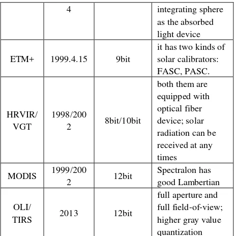
Table 1. Calibration characteristic of different sensor Solar calibration characteristics of typical satellite sensor are summarized in Table 2: The International Archives of the Photogrammetry, Remote Sensing and Spatial Information Sciences, Volume XL-7/W4, 2015
4 integrating sphere as the absorbed light device
ETM+ 1999.4.15 9bit
it has two kinds of solar calibrators: FASC, PASC.
HRVIR/ VGT
1998/200
2 8bit/10bit
both them are equipped with optical fiber device; solar radiation can be received at any times
MODIS 1999/200
2 12bit
Spectralon has good Lambertian OLI/
TIRS 2013 12bit
full aperture and full field-of-view; higher gray value quantization Table 2.Calibration characteristic of different sensor
3. CONCLUSION
According to the analysis of different types of domestic and foreign satellite sensors with different usage in chronological development order, it is not difficult to find below: (1) At the same time era, the same type of satellite is equipped with the same type of sensor, of which the calibration technology is almost the same. Therefore, as for typical satellite sensor at the same age, its calibration technology can largely represent that of other same types of the satellite sensors or with same usage. (2) This law of satellite sensors development not only exists in the visible/near-infrared solar calibration or lamp calibration but also applies to the blackbody calibration in the thermal infrared band.
ACKNOWLEDGEMENTS
This paper is financially supported by the National Natural Science of China under Grant numbers 41431179 and 41162011, GuangXi Governor Grant under approval number 2010-169, GuangXi Grand Natural Science Foundation under grant numbers 2012GXNSFCB053005, Guangxi Science & Technology Development Program under the Contract number GuiKeHe 14123001-4, and GuangXi Key Laboratory of Spatial Information and Geomatics Program (Contract No. GuiKeNeng110310801, 120711501, and 130511401), the “BaGuiScholars” program of the provincial government of Guangxi.
REFERENCES
Fox N P, Harrison N J, Hunt T M, et al., 2002a. Improved Transfer Standard Sources for Calibration of Earth Observation Instruments. Proc. SPIE, pp. 176-184.
MMERMAN G, NEUANN A, SIMNICHH, et al., 1993a. MOS/PRIROD an imaging VIS/NIR spectrometer for ocean remote sensing. SPIE, pp. 201-206.
J.A. Mendenhall, et al., 1999a. EO-1 advanced land imager in-flight calibration. The International Society for Optical Engineering, 3439, pp. 416-422.
Barsi J R, Schott, Palluconi F D, et al., 2003a. Landsat TM and ETM+ thermal band calibration. Canadian Journal of Remote Sensing, Canada, 29 (2), pp. 141-153.
Brian L.Markham, Dennis L.Helder., 2012a. Forty-year calibration record of earth-reflected radiance from Landsat: A review. Remote Sensing of Environment, 122, pp. 30-40. http://directory.eoportal.org/.
Geilman D I, Biggar S F, Dinguirard M C, et al., 1993a. Review of SPOT-1 and SPOT-2 calibrations at white sands from launch to the present. SPIE, 1938, pp. 118-125.
Patrice Henry, Aime Meygret., 2001a. Calibration of HRVIR and VEGETATION cameras on SPOT-4. Advances in Space Reserch, 28, pp. 49-58.
D.P.Roy, M.A.Wulder, et al., 2014a. Landsat-8: Science and product vision for terrestrial global change research. Remote Sensing of Environment, 145, pp. 154-172.
James R. Irons, John L. Dwyer, Julia A. Barsi., 2012a. The next Landsat satellite: The Landsat Data Continuity Mission. Remote Sensing of Environment, 122, pp. 11-21.
http://directory.eoportal.org/
Mingli GU., 2002a. Progress of the Solar Calibration Technique for Space-borne Multispectral Sensors. Chinese Space Science and Technology, 2, pp. 35-43.
Xiong X, Sun J, Barnes W., 2007a. Multiyear in-orbit calibration and performance of Terra MODIS reflective solar bands. IEEE Transactions on Geoscience and Remote Sensing, 45 (4), pp. 879-889.
Xiong X., 2006a. An overview of MODIS radiomertic calbration. Advances in atmospheric sciences, 23(1), pp. 69-79. LABANDIBAR JY, BAUDIN G, BAILLION Y., 2004a. Alcatel-Space in hyper/multispectral Earth observation programs from MERIS to SPECTRA. SPIE, 5234, pp. 232-242. http://directory.eoportal.org/.