IMAGING GEOMETRY AND POSITIONING ACCURACY OF DUAL SATELLITE
STEREO IMAGES: A REVIEW
J. Jeong*
Korea Ocean Satellite Centre, Korea Institute of Ocean Science and Technology, 787 Haean-ro(st). Ansan, Republic of Korea - [email protected]
Commission II, WG II/1
KEY WORDS: Dual-satellite Stereo, Geometric Weakness, High-resolution Satellite Image, Imaging Geometry, Positioning Accuracy
ABSTRACT:
Many previous studies have demonstrated the potential applications of stereo pairs obtained from high-resolution satellites for accurate geo-positioning, but it should be noted that they are based on the conventional use of single-satellite stereo images produced by integrating two images taken by the same satellite. Considering the emergence of various types of satellite data and the requirements to combine these data, it is important to investigate dual-satellite stereo images that integrate two images taken by different satellites. This study reviews the image geometry and positioning accuracy of dual-satellite stereo images based on several important studies, including comparisons with conventional single-satellite stereo images. In particular, the geometric limitation of dual-satellite stereo images often leads to very weak geometry, which degrades the positioning accuracy according to theoretical and experimental studies. Optimal ray intersection can improve the positioning accuracy using dual-satellite stereo images. This review improves our understanding of satellite stereo geometry and the handling of the dual-satellite stereo images, which are expected to become more common in real mapping applications.
* Corresponding author
1. INTRODUCTION
High-resolution satellite images have been used widely as primary sources for geo-positioning because they provide the absolute accuracy required for large-scale mapping as well as wide coverage and a short revisit time. Many investigations have employed stereo images taken by high-resolution satellites for geo-positioning (Fraser et al., 2002; Grodecki and Dial, 2003; Fraser et al., 2006; Tong et al., 2010), showing the absolute positioning accuracy comparable to or better than ground sample distances from precisely geo-referenced satellite stereo pairs. In particular, image pairs taken by Geoeye-1, WorldView-1/2, and KOMPSAT-3 can allow geo-positioning with sub-meter accuracy (Fraser and Ravanbakhsh, 2009; Aguilar et al., 2013; Jeong et al., 2016).
The previous investigations mentioned above demonstrated the potential of high-resolution satellite stereo images for mapping applications in terms of the imaging geometry and geo-positioning accuracy. However, it should be noted that they were based on the conventional use of single-satellite stereo images taken by the same satellite. High reliance on these types of image pairs may restrict the broader applications of satellite images. Considering the various types of high resolution satellite data that are available and the increased requirement to combine images in recent years, it is important to study the image geometry and positioning accuracy of dual-satellite stereo images produced by integrating two images taken using different satellites. The use of dual-satellite stereo images to replace conventional single-satellite stereo images will be highly beneficial in real mapping applications.
In recent years, several studies have investigated geo-positioning using multiple-satellite data integration. Thus, Li et al. (2007) analysed the geo-positioning accuracy that can be attained based on dual-satellite stereo images produced by integrating IKONOS and QuickBird images, where they focused mainly on the potential of dual-satellite image integration for geo-positioning. Jeong and Kim (2014) investigated the imaging geometry and positioning accuracy of dual-satellite stereo images more thoroughly, where the geometric limitations of dual-satellite stereo images were highlighted compared with conventional single-satellite stereo images. They also compared the geometric performance of different sensor models when using dual-satellite stereo images (Jeong and Kim, 2015). Jeong et al. (2015) analysed the geometric potential and limitations of integrating multiple satellite images, such as the integration of a single-satellite stereo image and a higher resolution single image, or stereo images taken by different satellites. Recently, formulae for estimating the positioning accuracy of dual-satellite stereo images were proposed based on the relationship between the satellite imaging geometry and positioning accuracy (Jeong and Kim, 2016).
The aim of this review is to clarify the geometric weaknesses that may occur after combining different satellite images, and to understand the handling of dual-satellite stereo images by considering the geometric characteristics of dual-satellite stereo images compared with single-satellite stereo images, as well as the effects of their characteristics on geo-positioning. Section 2 explains the stereo geometry of satellite images and highlights the geometric weaknesses that often affect dual-satellite stereo images but not conventional single-satellite stereo images. ISPRS Annals of the Photogrammetry, Remote Sensing and Spatial Information Sciences, Volume IV-2/W4, 2017
Section 3 describes the effects of these geometric weaknesses on the positioning accuracy according to theoretical and experimental studies. In section 4, we briefly explain the optimal ray intersection approach to more accurate dual-satellite stereo mapping. Section 5 gives our conclusions.
2. STEREO GEOMETRY OF A DUAL-SATELLITE STEREO IMAGE PAIR
2.1 Stereo Imaging Geometry
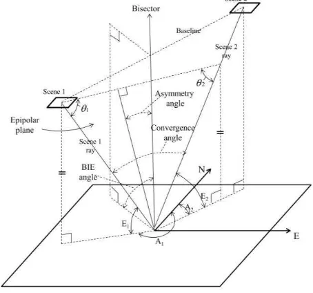
The stereo geometry of satellite images can be described based on the three angles, convergence, bisector elevation (BIE), and asymmetry angles, as shown in Figure 1 (Jeong and Kim, 2014; Jeong and Kim, 2016). The convergence angle is defined as the angle between two rays of the stereo pair. The convergence angle has been explained in many previous studies of stereo geo-positioning (Gugan and Dowman, 1988; Li et al., 2009; Dolloff and Theiss, 2010). The BIE angle is defined as the elevation angle of the bisector of the convergence angle, where the asymmetry angle is measured between the bisector and the line perpendicular to the baseline. The BIE and asymmetry angles were recently employed to indicate the levels of obliqueness and asymmetry, respectively, for the epipolar planes of dual-satellite stereo images (Jeong and Kim, 2014). These three angles describe the geometric stability of the epipolar plane. It should be noted that the asymmetry angle was redefined in a recently published study (Jeong and Kim, 2016).
Figure 1. Representation of the satellite stereo geometry showing the convergence, bisector elevation, and asymmetry
angles (Jeong and Kim, 2016).
The following formulae are used to estimate the three angles:
Convergence angle = 180° –θ1–θ2 (1)
As shown by the formulae, the azimuth and elevation angles for each sensor are used to calculate the three angles. This implies that the levels of the elevation angles and the differences in azimuth between two images may significantly affect the stability of the stereo geometry, and thus the stability of dual-satellite stereo images may differ from that of single-dual-satellite stereo images constructed using appropriate differences in the azimuth angle based on stereo acquisition mechanisms.
2.2 Imaging Geometry of Dual-satellite Stereo Images Two QuickBird, IKONOS, and KOMPSAT-2 images covering the same area in Daejeon, Korea are considered to understand the imaging geometry during dual-satellite integration. Figure 2 shows the sensor positions according to the azimuth and elevation angles, and altitude, which were obtained from on-board ephemeris data. The properties of the images are presented in Table 1 where the scenes are numbered in the acquisition time order. Some of these details were obtained from a previous study (Jeong and Kim, 2015).
Figure 2. Sensor positions during image acquisition.
As shown in Figure 2 and Table 1, the two QuickBird images were taken with along-track viewing angles of −27.6° and 29.2°, while maintaining an across-track viewing angle close to 0°. The two KOMPSAT-2 images were taken with roll angles of 14.3° and −28.4°, while maintaining a pitch angle close to 0°. The images were taken in two opposite directions by tilting the satellite in only one direction, i.e., along-track (pitch) or across-track (roll), but without tilting in the other direction. The two IKONOS images were not taken in opposite directions while tilting the along-track and across-track viewing angles simultaneously, but they were obtained at a regular azimuth angle interval by manoeuvring the system (Table 1). These conditions provided stable and strong geometry, with the normal range of convergence and BIE angles for the single-sensor stereos. By contrast, dual-single-sensor stereo images constructed randomly without these geometric conditions may have various geometries, which are often highly unstable and weak (Jeong and Kim, 2014; Jeong and Kim, 2015). For example, Figure 2 suggests that various types of epipolar planes ISPRS Annals of the Photogrammetry, Remote Sensing and Spatial Information Sciences, Volume IV-2/W4, 2017
will be constructed if one KOMPSAT-2 and one QuickBird are combined randomly.
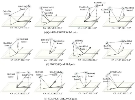
Figure 3 shows the stereo geometries for the three single-satellite stereo images: QuickBird, IKONOS, and KOMPSAT-2 stereo images. These pairs are general cases of single-satellite stereo images, which is the used method most widely for mapping applications. The convergence and BIE angles are within the normal ranges. In particular, the BIE angles are close to 90°, thereby clearly indicating that the epipolar planes of the
single-satellite stereo images are nearly orthogonal to the ground plane, except the IKONOS stereo has a BIE angle of 75°. In particular, Figure 3(a) provides a detailed explanation of the construction of the convergence and BIE angles.
Figure 4 shows the stereo geometries for dual-satellite stereo images: four pairs of QuickBird-KOMPSAT-2 stereo images, IKONOS-QuickBird stereo images, and KOMPSAT-2-IKONOS stereo images. The geometry of the dual-satellite stereo images differs from that of the general single-satellite
Figure 3. Stereo geometry of single-satellite stereo images.
Figure 4. Stereo geometry of dual-satellite stereo images.
stereo images. For example, the BIE angles of the single-satellite stereo images (Figure 3) are very close to 90°, but many of the BIE angles are less than 80° and as low as 70° for the dual-satellite stereo pairs (Figure 4 and Table 3). This indicates that the epipolar planes of the dual-satellite stereo images may be highly oblique compared with the single-satellite stereo images. In addition, very narrow convergence angles are frequent in the dual-satellite stereo images.
Considering that very small convergence and BIE angles often occur in dual-satellite stereo pairs, it is important to analyse the correlation between the changes in the convergence or BIE angles and the positioning accuracy. The asymmetry angles are not considered in this study because all the asymmetry angles are close to 0° in our examples, and thus they have little influence on the imaging geometry stability.
3. POSITIONING ACCURACY OF DUAL-SATELLITE STEREO IMAGES
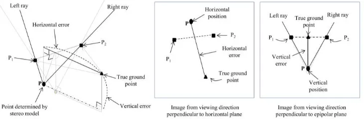
3.1 Effects of Imaging Geometry on Positioning Accuracy In this section, we consider the effects of the imaging geometry (convergence or BIE angles) on the positioning accuracy based on a close inspection of the process used to determine the intersection points from stereo images in order to understand how the geometric characteristics of dual-satellite stereo images affect the positioning accuracy. As shown in Figure 5, we initially assume an ideal epipolar plane (an appropriate convergence angle and BIE angle of 90°), which is generally present in basic single-satellite stereo configurations. The horizontal error can be considered as the distance between the
Figure 5. Stereo geometry layout in an ideal stereo geometry (Jeong and Kim, 2014).
Figure 6. Effects of changes in the convergence angle on the stereo geometry and positioning accuracy (Jeong and Kim, 2014).
Figure 7. Effects of changes in the BIE angle on the stereo geometry and positioning accuracy (Jeong and Kim, 2014). ISPRS Annals of the Photogrammetry, Remote Sensing and Spatial Information Sciences, Volume IV-2/W4, 2017
point T and the projection of the point P onto the horizontal plane. The layout of the horizontal plane is illustrated in the middle image in Figure 5, where P1 and P2 are the intersections of the left and right rays, respectively, with the horizontal plane. The magnitudes of the vectors TP1 and TP2 can be considered as the pointing errors of the left and right rays, respectively. The vertical error is the distance between the point P and the projection of the point T onto the epipolar plane. The layout of the epipolar plane is illustrated in the right image in Figure 5.
Figures 6 and 7 show the changes in the stereo geometry and positioning accuracy with different convergence angles and BIE angles, while the other parameters remain the same as the ideal case. In particular, it is assumed that the pointing error of the left and right rays is constant, and thus the vectors TP1 and TP2 are fixed in each image. Figure 6 shows that under the ideal stereo geometry a change in convergence angle will mainly affect the vertical error, with little effect on the horizontal error. Smaller convergence angles will increase the vertical error. This interpretation agrees with previous investigations of the effects of changes in the convergence angles on the positioning accuracy (Li et al., 2009; Dolloff and Theiss, 2012). Figure 7 indicates that changing the BIE angle will mainly affect the horizontal error, with little effect on the vertical error. With a fixed convergence angle, a change in the BIE angle from 90° will increase the horizontal error but decrease the vertical error slightly (Jeong and Kim, 2014; Jeong and Kim, 2015).
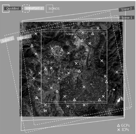
3.2 Positioning Accuracy of Dual-satellite Stereo Images Next, we validate the effects of the stereo geometry on the positioning accuracy using real satellite data. As described in Section 2, two QuickBird, IKONOS, and KOMPSAT-2 images covering the same area in Daejeon, Korea are considered in this experiment. Figure 8 shows the ground coverage of all the images used and the configuration of the ground control points (GCPs) and independent check points (ICPs). In total, 25 points were collected for the overlapping area of all the images, and 12 more points were collected for the overlapping areas between the QuickBird and KOMPSAT-2 images. The GCPs were used to update the initial model coefficients provided in the metadata and to establish the sensor models. The rational function model (RFM) with an affine model was used to establish the sensor model (Grodecki and Dial, 2003). The ICPs were used separately to evaluate the positioning accuracy of the stereo pairs. All of the ground points were determined at clearly identifiable spots, such as building corners or road roundabouts, and based on global positioning system (GPS) measurements taken in the field, which were subjected to differential GPS processing to ensure that the accuracy was higher than 10 cm.
Figure 8. Image coverage and GCP and ICP configurations.
In Table 2, the positioning accuracies of the single-satellite stereo pairs are represented as the root mean squared errors (RMSEs). The accuracies achieved using IKONOS and QuickBird stereo images are similar to the results achieved in previous studies at sub-pixel accuracy in the X, Y, and Z directions using RFM (Noguchi et al., 2004; Li et al., 2009). However, it should be noted that the errors in the X and Y directions were combined to represent the horizontal error in our example.
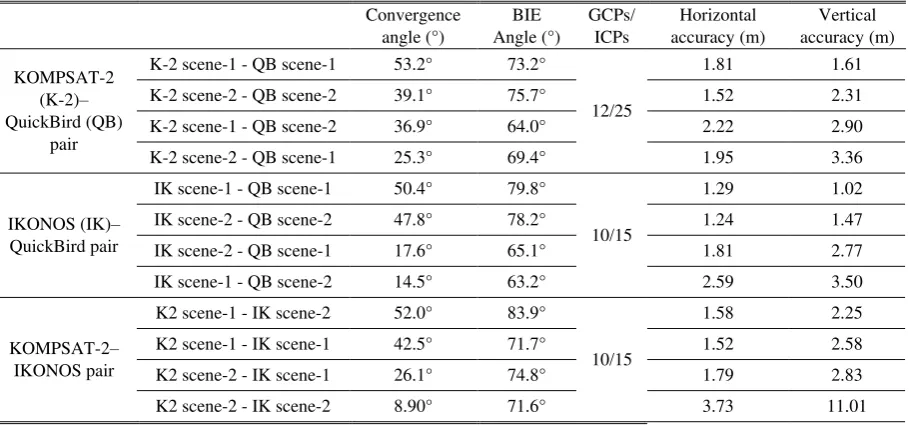
Table 3 shows the positioning accuracy of dual-satellite stereo image pairs with various geometries. The first example shows the results obtained with four stereo pairs by combining KOMPSAT-2 and QuickBird images, the second was obtained by combining IKONOS and QuickBird images, and the third by combining KOMPSAT-2 and IKONOS images. As mentioned earlier, the convergence and BIE angles of dual-satellite stereo images are very different from those of single-satellite stereo images. It can be seen that all the convergence angles of the dual-satellite stereo images vary from 53.2° to as little as 8.9° and the BIE angle ranges from 83.9° to as low as 63.2°. This observation clearly presents that the epipolar planes of some dual-satellite stereo pairs may exhibit low convergence or they can be highly oblique. All three examples of dual-satellite stereo images show that the vertical accuracy decreases with smaller convergence angles, which agrees with conventional
Table 1. Properties of the images used.
QuickBird IKONOS KOMPSAT-2
Scene-1 Scene-2 Scene-1 Scene-2 Scene-1 Scene-2
Date of acquisition 16 Jan. 2005 16 Jan. 2005 7 Feb. 2002 7 Feb. 2002 10 May
2007 6 May 2008
Azimuth angle 199.5° 5.2° 338.1° 234.9° 79.7° 256.7°
Elevation angle 59.5° 58.7° 66.5° 68.4° 58.2° 74.1°
Along-track view angle −27.6° 29.2° 22.1° −13.2° −1.3° 0.5°
Across-track view angle −5.4° −2.2° 8.8° 17.7° 14.3° −28.4°
GSD (column/row) 0.71/0.79 m 0.71/0.83 m 0.90/0.96 m 0.92/0.90 m 1.30/1.10 m 1.04/1.01 m ISPRS Annals of the Photogrammetry, Remote Sensing and Spatial Information Sciences, Volume IV-2/W4, 2017
theory regarding the use of single-satellite stereo images. The horizontal accuracy variation can be explained by the BIE angles. In the first example, it is observed that the BIE angles deviated from the ideal case degrade the horizontal accuracy. In addition, a comparison of the second and third pairs demonstrates the effects of the BIE angle on horizontal accuracy. The convergence angles are very similar for the two pairs whereas the BIE angles are not. Among the two pairs, the third pair with a smaller BIE angle has less horizontal accuracy. Overall, this observation also holds for the second and third examples. This experiment clearly illustrates the effects of the convergence and BIE angles on the positioning accuracy, where dual-satellite stereo images may produce very weak geometry.
4. OPTIMAL RAY INTERSECTION FOR GEO-POSITIONING USING DUAL-SATELLITE STEREO
IMAGES
Dual-satellite stereo image pairs may comprise two images with different resolutions and significantly different pointing accuracies. For example, a lower-resolution image is less accurate or precise than a higher-resolution image if we assume that the positioning error is proportional to the image resolution. In this case, the conventional intersection-finding algorithm based on an ordinary least-squares approximation can be affected significantly by errors in the lower-resolution image. The result is then determined based on the midpoint of the shortest segment connecting two corresponding rays. Therefore, this method must be refined to maximize the net precision based on a higher-resolution image, which is achieved by refining the protocol employed to calculate the intersection point. A suitable approach was proposed previously for integrating different satellite images (Chen et al., 2009), but the primary aim was to combine two different geometrical
correction models, i.e., direct georeferencing and RFM. A refined approach for determining the effective intersection point has still not been developed or validated fully. Thus, we consider the need to investigate its impact on the accuracy relative to conventional methods, as well as its potential and limitations based on useful examples, before implementing this approach for remote sensing.
Geo-positioning involves finding the intersection point of two rays that have been adjusted precisely via sensor orientation in the object space, as illustrated in Figure 9. Despite bundle adjustment, the two rays have individual pointing errors vectors TP1 and TP2 relative to the true ground point T. Therefore, the calculated intersection P for these two rays has horizontal and vertical errors relative to T.
Figure 9. Determining the intersection point from two stereo rays.
Table 2. Imaging geometry and positioning accuracy for the single-satellite stereo images.
Convergence angle
Table 3. Imaging geometry and positioning accuracy for the dual-satellite stereo images.
Convergence
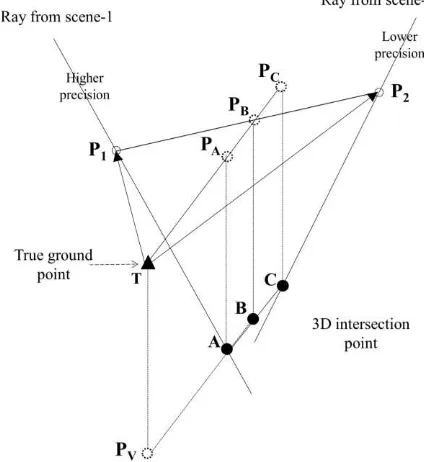
The horizontal error is denoted by TPH, which is the approximate midpoint of the vectors TP1 and TP2, and it is strongly influenced by the pointing errors in the individual image. The right-hand side of Figure 9 shows a magnified view of the intersection region. The two rays may be skewed (i.e., simultaneously non-intersecting and non-parallel) in three-dimensional space. Therefore, the selected intersection point minimizes the sum of the squared distances from the two rays, which is the midpoint in the shortest segment connecting the rays. This is a widely used approach but the solution obtained may be suboptimal when considering images in dual-satellite pairs with different resolutions and pointing errors. Assuming that the pointing error is generally proportional to the image resolution, then the error in the conventionally calculated intersection is weighted towards that of the lower-resolution image. Therefore, a refined intersection-finding method is needed to achieve better overall precision, and thus a more accurate mapping, by giving more weight to the higher-resolution image in a dual-satellite image pair.
Figure 10 shows an example of the intersections between the two rays of a dual-satellite stereo image pair, where it is assumed that scene 1 has a higher resolution and a higher pointing accuracy. The possible intersection points lie on the segment AC joining the two rays in the case where they do not intersect exactly. Conventionally, the intersection point B is selected according to an ordinary least-squares criterion, thereby yielding a horizontal error TPB. However, point A is clearly a better approximation in the horizontal direction but not in the vertical direction.
A refined approximation of the intersection point can be obtained by estimating the location (x and y) along the higher-precision ray that is at the same height (z) as the conventional intersection estimate. The rays can be matched precisely to their corresponding ground point based on the known sensor orientation of the single images in terms of the image coordinates (column, row). It is impossible to determine the x, y, and z coordinates at a given time from only a single ray, but x and y can be deduced for a given specified height. This concept
is called “forward mapping” and it is used to obtain better estimates of x and y based on the higher-resolution ray.
The quantitative results in Table 4 validate the refined intersections calculated using images originating from two different satellites. Four pairs of IKONOS (IK)–QuickBird (QB) stereo images were used for validation. The RMSEs calculated by comparing the 25 ICPs are presented for the three
horizontal positions. The quantitative results explicitly highlight the benefits of the refined intersection-finding method. The pairs clearly differ in terms of their accuracy using the different intersection calculation approaches. However, the refined method improves the horizontal positioning accuracy for all of the pairs. In particular, the effect of the refined method is stronger for the second and third pairs, where the convergence and BIE angles are very small, thereby leading to greater spatial uncertainty due to the weak geometry. The experimental results confirm the potential of the refined intersection calculation method for improving the positioning accuracy based on dual-satellite stereo image pairs, although there is little improvement in the vertical accuracy. This issue needs to be addressed in future research.
Figure 10. Dependence of the horizontal error on the intersection-finding method employed.
5. CONCLUSION
In this study, we reviewed the imaging geometry and positioning accuracy of dual-sensor stereo image pairs, where we showed that dual-sensor stereo image pairs may result in low convergence and a highly oblique geometry, thereby obtaining weak stereo geometry and degrading the accuracy. The convergence angle affects the vertical accuracy and the
Table 4. Comparison of the positioning accuracy using different intersection calculation approaches.
Combination Convergence
angle
BIE angle
Horizontal accuracy (RMSE)
Vertical accuracy (RMSE) LSE Refined intersection
Point B Point A Point C
IK/QB pairs
IK scene-1/QB scene-1 50.4° 79.8° 1.29 m 1.31 m 1.34 m 1.02 m
IK scene-1/QB scene-2 14.5° 63.2° 2.59 m 2.26 m 2.81 m 3.50 m
IK scene-2/QB scene-1 17.6° 65.1° 1.81 m 1.52 m 2.03 m 2.77 m
IK scene-2/QB scene-2 47.8° 78.2° 1.24 m 1.29 m 1.32 m 1.47 m
BIE angle affects the horizontal accuracy according to theoretical and experimental research. It is important to understand these findings to enhance the appropriate usage of satellite images. For example, it may be necessary to consider the BIE angles as well as the convergence angles to avoid weak stereo geometry when using dual-satellite stereo images, whereas it is usually sufficient to consider the convergence angles in the stereo combination when using single-satellite images. The optimal ray intersection method for dual-satellite stereo mapping can also improve the positioning accuracy. The analysis presented in this study improves our understanding of satellite stereo geometry and the handling of dual-sensor stereo images, which are expected to become more common in real mapping applications.
ACKNOWLEDGEMENTS
This research was supported by the projects entitled "Development of the integrated data processing system for GOCI-II" and "Research for Application of Geostationary Ocean Color Imager" funded by the Ministry of Oceans and Fisheries, Korea.
REFERENCES
Aguilar, M.A., M.M. Saldana, and F.J. Aguilar, 2013. Assessing geometric accuracy of the orthorectification process from GeoEye-1 and WorldView-2 panchromatic images. International Journal of Applied Earth Observation and Geoinformation, 21, pp. 427–435.
Chen, L., Chang W. and Teo, T., 2009. Geometric Integration of heterogeneous models for multisatellite image positioning. IEEE Transaction on Geoscience and Remote Sensing, 50(7), pp. 2802–2809.
Dolloff, J., and Settergren, R., 2010. An assessment of WorldView-1positional accuracy based on fifty contiguous stereo pairs of imagery. Photogrammetric Engineering & Remote Sensing, 76(8), pp. 935–943.
Fraser, C.S., Baltsavias, E., Gruen, A., 2002. Processing of Ikonos imagery for submetre 3D geopositioning and building extraction. ISPRS Journal of Photogrammetry and Remote Sensing, 56(3), pp. 177–194.
Fraser, C.S., Dial, G., Grodecki, J., 2006. Sensor orientation via RPCs. ISPRS Journal of Photogrammetry and Remote Sensing, 60 (3), pp. 182–194.
Fraser, C.S., Ravanbakhsh, M., 2009. Georeferencing accuracy of GeoEye-1 imagery. Photogrammetric Engineering & Remote Sensing, 75(6), pp. 634–640.
Grodecki, J., Dial, G., 2003. Block adjustment of high-resolution satellite images described by rational polynomials. Photogrammetric Engineering & Remote Sensing, 69(1), pp. 59–68.
Gugan, D.J., and Dowman, I.J., 1988. Topographic mapping from SPOT imagery. Photogrammetric Engineering & Remote Sensing, 54(10), pp. 1409–1414.
Jeong, J., and Kim, T., 2014. Analysis of dual-sensor stereo geometry and its positioning accuracy. Photogrammetric Engineering & Remote Sensing, 80(7), pp. 653–662.
Jeong, J. and Kim, T., 2015. Comparison of positioning accuracy of a rigorous sensor model and two rational function models for weak stereo geometry. ISPRS Journal of Photogrammetry and Remote Sensing, 108, pp. 172–182.
Jeong, J. and Kim, T., 2016. Quantitative Estimation and Validation of the Effects of the Convergence, Bisector Elevation, and Asymmetry Angles on the Positioning Accuracies of Satellite Stereo Pairs. Photogrammetric Engineering & Remote Sensing, 82(8), pp. 625–633.
Jeong, J., Kim, J., Kim, T. and Rhee, S., 2016. Evaluation of the performance of KOMPSAT-3 stereo images in terms of positioning and the generation of digital surface models. International Journal of Remote Sensing, 7(10), pp. 955–964.
Jeong, J., Yang, C. and Kim, T., 2015. Geo-Positioning Accuracy Using Multiple-Satellite Images: IKONOS, QuickBird, and KOMPSAT-2 Stereo Images. Remote Sensing, 7(4), pp. 4549–4564.
Li, R., X. Niu, C. Liu, B. Wu, and Deshapnde, S., 2009. Impact of imaging geometry on 3D Geopositioning Accuracy of Stereo Ikonos Imagery. Photogrammetric Engineering & Remote Sensing, 75(9), pp. 1119–1126.
Li, R., F. Zhou, X. Niu, and Di, K., 2007. Integration of Ikonos and QuickBird imagery for geopositioning accuracy analysis, Photogrammetric Engineering & Remote Sensing, 73(9), pp. 1067– 1074.
Tong, X., Liu, S., Weng, Q., 2010. Bias-corrected rational polynomial coefficients for high accuracy geo-positioning of QuickBird stereo imagery. ISPRS Journal of Photogrammetry and Remote Sensing, 65(2), pp. 218–226.