PAUL KIMMEL
0-07-148671-2
The material in this eBook also appears in the print version of this title: 0-07-226182-X.
All trademarks are trademarks of their respective owners. Rather than put a trademark symbol after every occurrence of a trade-marked name, we use names in an editorial fashion only, and to the benefit of the trademark owner, with no intention of infringe-ment of the trademark. Where such designations appear in this book, they have been printed with initial caps.
McGraw-Hill eBooks are available at special quantity discounts to use as premiums and sales promotions, or for use in corporate training programs. For more information, please contact George Hoare, Special Sales, at [email protected] or (212) 904-4069.
TERMS OF USE
This is a copyrighted work and The McGraw-Hill Companies, Inc. (“McGraw-Hill”) and its licensors reserve all rights in and to the work. Use of this work is subject to these terms. Except as permitted under the Copyright Act of 1976 and the right to store and retrieve one copy of the work, you may not decompile, disassemble, reverse engineer, reproduce, modify, create derivative works based upon, transmit, distribute, disseminate, sell, publish or sublicense the work or any part of it without McGraw-Hill’s prior con-sent. You may use the work for your own noncommercial and personal use; any other use of the work is strictly prohibited. Your right to use the work may be terminated if you fail to comply with these terms.
THE WORK IS PROVIDED “AS IS.” McGRAW-HILL AND ITS LICENSORS MAKE NO GUARANTEES OR WARRANTIES AS TO THE ACCURACY, ADEQUACY OR COMPLETENESS OF OR RESULTS TO BE OBTAINED FROM USING THE WORK, INCLUDING ANY INFORMATION THAT CAN BE ACCESSED THROUGH THE WORK VIA HYPERLINK OR OTH-ERWISE, AND EXPRESSLY DISCLAIM ANY WARRANTY, EXPRESS OR IMPLIED, INCLUDING BUT NOT LIMITED TO IMPLIED WARRANTIES OF MERCHANTABILITY OR FITNESS FOR A PARTICULAR PURPOSE. McGraw-Hill and its licen-sors do not warrant or guarantee that the functions contained in the work will meet your requirements or that its operation will be uninterrupted or error free. Neither McGraw-Hill nor its licensors shall be liable to you or anyone else for any inaccuracy, error or omission, regardless of cause, in the work or for any damages resulting therefrom. McGraw-Hill has no responsibility for the con-tent of any information accessed through the work. Under no circumstances shall McGraw-Hill and/or its licensors be liable for any indirect, incidental, special, punitive, consequential or similar damages that result from the use of or inability to use the work, even if any of them has been advised of the possibility of such damages. This limitation of liability shall apply to any claim or cause what-soever whether such claim or cause arises in contract, tort or otherwise.
We hope you enjoy this
McGraw-Hill eBook! If
you’d like more information about this book,
its author, or related books and websites,
please
click here.
Paul Kimmel is the Chief Architect and a founder of Software Conceptions, Inc. He has been designing and implementing object-oriented software since 1990 and has more than a dozen years of experience with modeling languages and was an early adopter of the Unified Modeling Language. Paul has helped design and implement solutions using the UML for some of the largest corporations in the world from international banks, multinational telecommunications companies, logistics and shipping companies, Department of Defense agencies and national and international governmental groups.
CHAPTER 1
CHAPTER 2
CHAPTER 3
CHAPTER 4
CHAPTER 5
CHAPTER 6
CHAPTER 7
CHAPTER 8
CHAPTER 9
CHAPTER 10
APPENDIX A
A Picture Is Worth a Thousand Lines of Code 1 Start at the Beginning with Use Cases 17 Diagramming Features as Processes 47 Discovering Behaviors with Interaction Diagrams 81 What Are the Things That Describe My Problem? 101 Showing How Classes Are Related
Using State Chart Diagrams
Modeling Components Fit and Finish
Visualizing Your Deployment Topology
Final Exam
Selected Bibliography
Index
131
157
175
185
197
209
225
227
CONTENTS
zyxwvutsrqponmlkjihgfedcbaZYXWVUTSRQPONMLKJIHGFEDCBAAcknowledgments xv Introduction xvii
CHAPTER 1 A Picture Is Worth a Thousand Lines of Code 1
Understanding Models 2 Understanding the UML 3 The Evolution of Software Design 3 If No One Is Modeling, Why Should You? 5 Modeling and the Future of Software
Development 5 Modeling Tools 5 Using Models 6 Creating Diagrams 7 Reviewing Kinds of Diagrams 7 Finding the Finish Line 12
How Big Should a Diagram Be? 13 How Much Text Should Supplement
My Models? 13 Get a Second Opinion 13
ix
CHAPTER 2
CHAPTER 3
Contrasting Modeling Languages with Process 14 Quiz 14 Answers 16
Start at the Beginning with Use Cases 17
Making the Case for Use Cases 18 Prioritizing Capabilities 19 Communicating with Nontechnophiles 20 Using Use Case Symbols 21 Actor Symbols 21 Use Cases 21 Connectors 22 Including and Extending Use Cases 25 Annotating Use Case Diagrams 27 Creating Use Case Diagrams 32 How Many Diagrams Is Enough? 34 Example Use Case Diagrams 34 Driving Design with Use Cases 43 Quiz 44 Answers 46
Diagramming Features as Processes 47
CHAPTER 4
CHAPTER 5zyxwvutsrqponmlkjihgfedcbaZYXWVUTSRQPONMLKJIHGFEDCBA
Showing Exceptions in Activity Diagrams 70 Terminating Activity Diagrams 71 Creating Activity Diagrams 72 Reengineering Process 73 Reengineering a Subactivity 74 Knowing When to Quit 77 Quiz 77 Answers 79
Discovering Behaviors with
Interaction Diagrams 81
Elements of Sequence Diagrams 82 Using Object Lifelines 83 Activating a Lifeline 84 Sending Messages 85 Adding Constraints and Notes 87 Using Interaction Frames 87 Understanding What Sequences Tell Us 91 Discovering Objects and Messages 92 Elements of Collaboration (or Communication)
Diagrams 94 Equating Design to Code 96 Quiz 97 Answers 99
What Are the Things That DescribezyxwvutsrqponmlkjihgfedcbaZYXWVUTSRQPONMLKJIHGFEDCBA
My Problem? 101
CHAPTER 6
CHAPTER 7
Modeling Primitives 120 Modeling Enumerations 121 Indicating Namespaces 122 Figuring Out the Classes You Need 123 Using the Naive Approach 124 Discovering More than Domain
Analysis Yields 124 Quiz 128 Answers 130
Showing How Classes Are Related 131
Modeling Inheritance 132 Using Single Inheritance 132 Using Multiple Inheritance 135 Modeling Interface Inheritance 139 Whiteboarding 139 Using Realization 140 Describing Aggregation and Composition 143 Showing Associations and Association Classes 145 Exploring Dependency Relationships 150 Adding Details to Classes 153 Quiz 153 Answers 155
Using State Chart Diagrams 157
CHAPTER 8
CHAPTER 9
CHAPTER 10
Modeling Components 175zyxwvutsrqponmlkjihgfedcbaZYXWVUTSRQPONMLKJIHGFEDCBA Introducing Component-Based Design 177
Using a Top-Down Approach to Design 177 Using a Bottom-Up Approach to Design 178 Modeling a Component 178 Specifying Provided and Required Interfaces 179 Exploring Component Modeling Styles 180 Diagramming Components for Consumers 180 Diagramming Components for Producers 182 Quiz 183 Answers 184
Fit and Finish 185
Modeling Dos and Don'ts 186 Don't Keep Programmers Waiting 187 Work from a Macro View to a Micro View 187 Document Sparingly 187 Find an Editor 188 Be Selective about Diagrams
You Choose to Create 188 Don't Count on Code Generation 188 Model and Build from Most Risky
to Least Risky 188 If It's Obvious Don't Model It 189 Emphasize Specialization 189 Using Known State Patterns 189 Refactoring Your Model 192 Adding Supporting Documentation 192 Validating Your Model 193 Quiz 193 Answers 195
Visualizing Your Deployment Topology 197
Modeling Nodes 198
Adding Communication Paths 204 Quiz 206 Answers 207
APPENDIX A Final Exam 209
Answers 223
Selected Bibliography 225
Well into my second decade of writing I have Wendy Rinaldi at McGraw-Hill/Osborne, along with Alexander McDonald and my agent David Fugate at Waterside to thank for this opportunity to write what I believe you will find an informative, entertaining, and easy to follow book on the Unified Modeling Language.
I also want to thank my friend Eric Cotter from Portland, Oregon, for offering to provide technical editing for UML DeMystified. Eric did an excellent job of finding my mistakes, omissions, and in improving the explanations.
Thank you to my hosts at the Ministry of Transportation Ontario in St. Catharines, Ontario. Collaborating with you on CIMS was an enjoyable process and exploring my models and designs with you provided excellent fodder for this book. Thank you Novica Kovacevic, Jennifer Fang, Rod, Marco Sanchez, Chris Chartrand, Sergey Khudoyarov, Dalibor Skacic, Michael Lam, Howard Bertrand, and David He from Microsoft. It was a pleasure working with and learning from all of you.
In 2004, along with Bill Maas, Paul Emery, Sainney Drammeh, Bunmi Akinyemichu, and Ryan Doom, the Greater Lansing area .NET Users Group (glugnet .org) was formed, and I'd like to say hello to all of the great glugnet members and supporters. We meet the third Thursday of every month at 6:00 P.M. on the beautiful campus of Michigan State University. Thanks to MSU for permitting to use their excellent facilities in the Engineering Building and Anthony Hall.
While working in Ontario my sustenance was graciously provided for at Prudhom-mes in Vineland, Ontario, at exit 55 and 57 and the Honest Lawyer in St. Catharines, Ontario, Canada. Thanks to Lis, Jen Cheriton, Everett, Kathryn, and Kim for food and adult beverage, and the staff of the Honest Lawyer for the wireless access.
Last but not least, I owe a gratitude of debt to my wife Lori and four children, Trevor, Douglas, Alex, and Noah, playing the role of biggest fans and supporters. A family is the greatest blessing. (I would also like to introduce the newest member of our family Leda, an energetic chocolate lab, who waits patiently at my feet as a subtle reminder to push back from the computer and go do something else every once in a while.)
XV
New inventions often occur out of necessity and are documented on napkins long before, if ever, an authoritative and formal definition is provided. The Unified Modeling Language (UML) is just such an example. Individual aspects of what ultimately became the UML were defined by Ivar Jacobson, James Rumbaugh, and Grady Booch out of necessity long before their individual contributions were consolidated into a single definition.
There is a mixed problem with formal and standard specifications. Generally, for an august body of scientists to ratify something it is to be unambiguously and rigorously defined. If you look up the definition of the UML, you will find meta-models that describe to minute detail what is and what is not the UML. The effect is much like reading congressional reports: long-winded, dry, tedious, and with an occasional juicy tidbit. Think of formal definitions versus practical applications like this: there are specific rigorous rules that define something as simple as algebra, but you don't need to know them even though we perform or rely on simple algebra in everyday tasks such as pumping gas. For example, price per gallon multiplied by number of gallons = total price. With simple text-to-character substitution we can create arithmetic equations, p * g = t, that start to look like those confusing equations from school but make it notationally convenient to determine any quantity of the equation. What I mean is that even people that would identify themselves as math challenged perform math everyday for practical purposes without ever thinking of it what they are doing as solving math problems.
That's the objective behind this book. There are formal and rigorous definitions of the UML and they exist for good reason, but you don't have to know them to use the UML in a practical way. UML linguists have to know the UML intimately to rigorously define just like English professors know grammar intimately to teach it, but you don't have to be an English teacher to communicate effectively. This is true of the UML
too; you don't have to know every detail about the UML to use it effectively.zyxwvutsrqponmlkjihgfedcbaZYXWVUTSRQPONMLKJIHGFEDCBA
xvii
UML DeMystified is written in simple prose and designed to make the UML practical and an effective tool for communicating software analysis and design.
There are many books on process and the UML does not define a process. However, this book is organized in such a manner that if you create the kinds of models as needed in the order in which they appear in this book, then you have a practical beginning of a usable process.
UML DeMystified is a modest-sized book but it is a compilation of more than a dozen years of practical experience working with some of the largest and best known companies in the world as well as many well-known smaller companies, and the UML described in this book is pragmatic, practical, and applicable whether you are building small, medium, or very large applications. In short, UML DeMystified leaves the ivory tower fluff and rigor to other texts and tells you what you need to
A Picture Is
Worth a Thousand
Lines of Code
Pictures of little stick people represent the oldest recorded form of communication in human history. Some of these cave art have been dated to be as old as 75,000 years. Oddly enough, here we are at the turn of the twenty-first modern century, and we are still using little stick figures to convey information. That's right, a little stick man we'll call Esaw is a central character in one of the newest languages developed by humans (Figure 1-1).zyxwvutsrqponmlkjihgfedcbaZYXWVUTSRQPONMLKJIHGFEDCBA
1
Figure 1-1 Esaw, who is referred to as an actor in the UML.
The language I am talking about is called the Unified Modeling Language, or UML. The UML is a language just as sure as, Pascal, C# (C sharp), German, English, and Latin are languages. And the UML is probably one of the newest languages in-vented by humankind, inin-vented around 1997.
As with other languages, the UML was invented out of necessity. Moreover, as with many languages, the UML uses symbols to convey meaning. However, unlike organic languages such as English or German that evolve over time from common use and adaptation, the UML was invented by scientists, which unfortunately is a problem. Scientists are very smart, but they often are not very good at explaining things to those less scientific. This is where I come in.
In this chapter we will look at the origin and evolution of the UML. We also will talk about how to create pictures using the UML, how many and what types of pic-tures to create, what those picpic-tures should convey, and most important, when to stop drawing pictures and start writing code.
Understanding Models
A model is a collection of pictures and text that represent something—for our pur-poses, software. (Models do not have to represent software, but we will narrow our scope to software models.) A model is to software what a blueprint is to a house.
Models are valuable for many specific reasons. Models are valuable because they consist of pictures to a large extent, and even simple pictures can convey more information than a lot of text, e.g., code. This is consistent with the somewhat mod-ified old adage that a picture speaks a thousand lines of code. Models are valuable because it is easier to draw some simple pictures than it is to write code or even text that describes the same thing. Models are valuable because it is cheaper, faster, and it is easier to change models than it is to change code. The simple truth is that cheap,
Unfortunately, if everyone uses different pictures to mean the same thing, then the pictures add to the confusion rather than mitigate it. This is where the UML comes in.
Understanding the UML
The UML is an official definition of a pictoral language where there are commonsymbols and relationships that have one common meaning. If every participant speaks UML, then the pictures mean the same thing to everyone looking at those pictures. Learning the UML, therefore, is essential to being able to use pictures to cheaply, flexibly, and quickly experiment with solutions.
It is important to reiterate here that it is faster, cheaper, and easier to solve prob-lems with pictures than with code. The only barrier to benefiting from modeling is learning the language of modeling.
The UML is a language just like English or Afrikaans is a language. The UML comprises symbols and a grammar that defines how those symbols can be used. Learn the symbols and grammar, and your pictures will be understandable by every-one else who recognizes those symbols and knows the grammar.
Why the UML, though? You could use any symbols and rules to create your own modeling language, but the trick would be to get others to use it too. If your aspira-tions are to invent a better modeling language, then it isn't up to me to stop you. You should know that the UML is considered a standard and that what the UML is and isn't is defined by a consortium of companies that make up the Object Management Group (OMG). The UML specification is defined and published by the OMG at
www. omg. org.
The Evolution of Software Design
If you feel that you are late to the UML party, don't fret—you are actually an early arrival. The truth is that the UML is late to the software development party. I work all over North America and talk with a lot of people at lots of very big software companies, and the UML and modeling are just starting to catch on. This is best exemplified by Bill Gates' own words after his famous "think week" in 2004, where Gates is reported to have talked about the increasing importance of formal analysis and design (read UML) in the future. This sentiment is also supported by
The UML represents a formalization of analysis and design, and formalization always seems to arrive last. Consider car makers in the last century. Around the turn of the last century, every buggy maker in Flint, Michigan, was turning horse car-riages into motorized carcar-riages, i.e., cars. This occurred long before great universities such as Michigan State University (MSU) were turning out mechanical engineers trained to build cars and software tools such as computer-aided design (CAD) pro-grams that are especially good at drawing complex items such as car parts. The evolution of formalized automobile engineering is consistent with the evolution of formalized software engineering.
About 5000 years ago, the Chinese created one of the first computers, the abacus. About 150 years ago, Charles Babbage invented a mechanical computing machine. In 1940, Alan Turing defined the Turing computing machine and Presper Eckert and John Mauchly invented Eniac. Following computing machines came punch cards and Grace Hopper's structured analysis and design to support Cobol develop-ment. In the 1960s, Smalltalk, an object-oriented language, was invented, and in 1986, Bjarne Stroustrop invented what is now known as C++. It wasn't until around this same time period—the 1980s—that very smart men like Ivar Jacobson, James Rumbaugh, and Grady Booch started defining elements of modern software analy-sis and design, what we now call the UML.
In the late 1980s and early 1990s, modeling notation wars were in full gear, with different factions supporting Jacobson, Rumbaugh, or Booch. Remember, it wasn't until 1980 that the average person could purchase and own—and do something use-ful with—a personal computer (PC). Jacobson, Rumbaugh, and Booch each used different symbols and rules to create their models. Finally, Rumbaugh and Booch began collaborating on elements of their respective modeling languages, and Jacob-son joined them at Rational Software.
In the mid-1990s, the modeling elements of Rumbaugh [Object Modeling Tech-nique (OMT)], Booch (Booch method), and Jacobson (Objectory and Use Cases)— Rumbaugh, Jocobson, and Rumbaugh are referred to as "the three amigos"—were merged together to form the unified modeling process. Shortly thereafter, process was removed from the modeling specification, and the UML was born. This occurred very recently, in just 1997. The UML 2.0 specification stabilized in October 2004; that's right, we are just now on version 2.
If No One Is Modeling, Why Should You?
A rational person might ask: Why then, if Bill Gates is making billions writing software without a significant emphasis on formal modeling, should I care about the UML? The answer is that almost 80 percent of all software projects fail. These projects exceed their budgets, don't provide the features customers need or desire, or worse, are never delivered.
The current trend is to outsource software development to developing or third-world nations. The basic idea is that if American software engineers are failing, then perhaps paying one-fifth for a Eurasian software developer will permit compa-nies to try five times as often to succeed. What are these outsourcing compacompa-nies finding? They are discovering that the United States has some of the best talent and resources available and that cheap labor in far-away places only introduces addi-tional problems and is no guarantee of success either. The real answer is that more time needs to be spent on software analysis and design, and this means models.
Modeling and the Future of Software Development
A growing emphasis on formal analysis and design does not mean the end of the software industry's growth. It does mean that the wild, wild west days of the 1980s and 1990s eventually will come to a close, but it is still the wild, wild hacking west out there in software land and will be for some time.
What an increasing emphasis on software analysis and design means right now is that trained UML practitioners have a unique opportunity to capitalize on this growing interest in the UML. It also means that gradually fewer projects will fail, software quality should improve, and more software engineers will be expected to learn the UML.
Modeling Tools
Modeling tools can be very useful, but it is possible to model on scraps of paper. Thankfully, you don't have to go that far. Love it or hate it, Microsoft is very good at driving down the cost of software. If you have a copy of MSDN, then you have a modeling tool that is almost free, Visio. Visio is a good tool, ably capable of produc-ing high-quality UML models, and it won't break your budget.1
In keeping with the theme of this book—demystifying UML—instead of break-ing the bank on Together or Rose, we are gobreak-ing to use the value-priced Visio. If you want to use Rose XDE, Together, or some other product, you are welcome to do so, but after reading this book, you will see that you can use Visio and create profes-sional models and save yourself hundreds or even thousands of dollars.
Using Models
Models consist of diagrams and pictures. The intent of models is that they are cheaper to produce and experiment with than code. However, if you labor over what models to draw, when to stop drawing and start coding, or whether your models are perfect or not, then you will slowly watch the cost and time value of models dwin-dle away.
You can use plain text to describe a system, but more information can be con-veyed with pictures. You could follow the extreme Programming (XP) dictum and code away, refactoring as you go, but the details of lines of code are much more complex than pictures, and programmers get attached to code but not to pictures. (I don't completely understand the psychology of this code attachment, but it really does exist. Just try to constructively criticize someone else's code, and watch the conversation deteriorate very quickly into name calling.) This means that once code is written, it is very hard to get buy-in from its coder or a manager to make modifi-cations, especially if the code is perceived to work. Conversely, people will gladly tinker with models and accept suggestions.
Finally, because models use simple symbols, more stakeholders can participate in design of the system. Show an end user a hundred lines of code, and you can hear the crickets chirping; show such an end user an activity diagram, and that same person can tell you if you have captured the essence of how that task is performed correctly.
'Microsoft has a new program that permits you to purchase MSDN Universal, which includes Visio,
Creating Diagrams
The first rule of creating models is that code and text are time-consuming, and wedon't want to spend a lot of time creating text documents that no one wants to read. What we do want to do is to capture the important parts of the problem and a solu-tion accurately. Unfortunately, this is not a prescripsolu-tion for the number or variety of diagrams we need to create, and it does not indicate how much detail we need to add to those diagrams.
Toward the end of this chapter, in the section "Finding the finsh line.", I will talk more about how one knows that one has completed modelling. Right now, let's talk about the kinds of diagram we may want to create.
Reviewing Kinds of Diagrams
There are several kinds of diagrams that you can create. I will quickly review the kinds of diagrams you can create and the kinds of information each of these dia-grams is intended to convey.
Use Case Diagrams
Use case diagrams are the equivalent of modern cave art. A use case's main sym-bols are the actor (our friend Esaw) and the use case oval (Figure 1-2).
Use case diagrams are responsible primarily for documenting the macro require-ments of the system. Think of use case diagrams as the list of capabilities the system must provide.
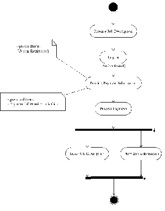
Activity Diagrams
An activity diagram is the UML version of a flowchart. Activity diagrams are used to analyze processes and, if necessary, perform process reengineering (Figure 1-3).
Figure 1-3 An activity diagram showing how Esaw goes about finding food.
An activity diagram is an excellent tool for analyzing problems that the system ultimately will have to solve. As an analysis tool, we don't want to start solving the problem at a technical level by assigning classes, but we can use activity diagrams to understand the problem and even refine the processes that comprise the problem.
Class Diagrams
Class diagrams are used to show the classes in a system and the relationships
Figure 1-4 A single class diagram, perhaps one of many, that conveys a facet of the system being designed.
diagram, and it isn't necessary to show all the classes in a single, monolithic class diagram. The greatest value is to show classes and their relationships from various perspectives in a way that will help convey the most useful understanding.
Class diagrams show a static view of the system. Class diagrams do not describe behaviors or how instances of the classes interact. To describe behaviors and inter-actions between objects in a system, we can turn to interaction diagrams.
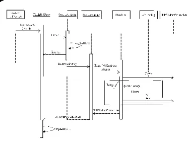
Interaction Diagrams
There are two kinds of interaction diagrams, the sequence and the collaboration.
These diagrams convey the same information, employing a slightly different per-spective. Sequence diagrams show the classes along the top and messages sent between those classes, modeling a single flow through the objects in the system. Collaboration diagrams use the same classes and messages but are organized in a spatial display. Figure 1-5 shows a simple example of a sequence diagram, and Figure 1-6 conveys the same information using a collaboration diagram.
A sequence diagram implies a time ordering by following the sequence of mes-sages from top left to bottom right. Because the collaboration diagram does not indicate a time ordering visually, we number the messages to indicate the order in which they occur.
Some tools will convert interaction diagrams between sequence and collabora-tion automatically, but it isn't necessary to create both kinds of diagrams. Generally,
Figure 1-5 A single sequence diagram demonstrating how food is gathered and prepared.
State Diagrams
Whereas interaction diagrams show objects and the messages passed between them, a state diagram shows the changing state of a single object as that object passes through a system. If we continue with our example, then we will focus on Esaw and how his state is changing as he forages for food, finds food, and consumes it (Figure 1-7).
Figure 1-6
behavior.
A collaboration diagram that conveys the same gathering and consuming
Component Diagrams
The UML defines various kinds of models, including analysis, design, and imple-mentation models. However, there is nothing forcing you to create or maintain three models for one application. An example of a diagram you might find in an imple-mentation model is a component diagram. A component diagram shows the
components—think subsystems—in the final product.zyxwvutsrqponmlkjihgfedcbaZYXWVUTSRQPONMLKJIHGFEDCBA
Figure 1-7 A state diagram (or statecharf) showing the progressive state as Esaw forages
I'll cover deployment diagrams later in this book but defer citing an example for now. Generally, a component diagram is a bit like a class diagram with component symbols.
Other Diagrams
There are other kinds or variations of diagrams we can create. For example, a de-ployment topology diagram will show you what your system will look like deployed. Such a diagram typically contains symbols representing things such as Web servers, database servers, and various and sundry devices and software that make up your solution. This kind of diagram is more common when you are building «-tiered distributed systems.
I will show you examples of some of these diagrams later in this book. Remember that the key to modeling is to modeling interesting aspects of your system that help to clarify elements that may not be obvious, as opposed to modeling everything.
Finding the Finish Line
The hardest part of modeling is that it is so new that UML models are subjected to some of the same language wars object-oriented projects suffered from during the last decade. I encourage you to avoid these language wars as mostly unproductive academic exercises. If you find yourself getting hung up on whether something is or isn't good UML, then you are heading toward analysis (and design) paralysis.
The goal is to be as accurate as possible in a reasonable amount of time. Poorly designed software is bad enough, but no software is almost always worse. To deter-mine if you are finished with a particular diagram or model, ask the question: Does the diagram or model convey my understanding, meaning, and intent? That is, is the diagram or model good enough? Accuracy is important because others need to read your models, and idiomatic mistakes mean that the models will be harder for others to read.
How Many Diagrams Do I Create?
How Big Should a Diagram Be?
Determining how big a model needs to be is another good question to decide. If a given model is too big, then it may add to confusion. Try to create detailed mod-els — but not too detailed. As with programming, creating UML modmod-els takes practice.
Solicit feedback from different constituencies. If the end users think that an anal-ysis diagram adequately and correctly captures the problem, then move on. If the programmers can read a sequence and figure out how to implement that sequence, then move on. You can always add details if you must.
How Much Text Should Supplement My Models?
A fundamental idea for using pictures for modeling instead of long-winded text is that pictures convey more meaning in a smaller space and are easier to manipulate. If you add too much text — constraints, notes, or long documents — then you are defeating the purpose of this more concise pictorial notation.
The best place for text is the use case. A good textual description in each use case can clarify precisely what feature that use case supports. I will demonstrate some good use case descriptions in Chapter 2.
You are welcome to add any clarifying text you need, but the general rule for text is analogous to the rule for comments in code: Only comment things that are rea-sonably subject to interpretation.
Finally, try to document everything in your modeling tool as opposed to a sepa-rate document. If you find that you need or the customer requires a written architectural overview, defer this until after the software has been produced.
Get a Second Opinion
Contrasting Modeling Languages
with Process
The UML actually began life as the Unified Process. The inventors quickly realized that programming languages do not dictate process, and neither should modeling languages. Hence process and language were divided.
There are many books on process. I don't think one process represents the best fit for all projects, but perhaps one of the more flexible processes is the Rational Unified Process. My focus in this book is on the UML, not on any particular pro-cess. I will be suggesting the kinds of models to create and what they tell you, but I encourage you to explore development processes for yourself. Consider exploring the Rational Unified Process (RUP), the Agile process, extreme Programming (XP), and even Microsoft's Services Oriented Architecture (SOA). (SOAis more of an architectural approach using elements like XML Web Services, but it offers some good techniques.)
I am not an expert on every process, but here is a summary that will provide you with a starting point. The RUP is a buffet of activities centered on the UML that defines iterative, small waterfalls macro phases, including inception, elaboration, construction, and transition. XP is constructive hacking. The idea generally is based on building on your understanding, expecting things to change, and using tech-niques such as refactoring and pair programming to support changes as your understanding grows. Microsoft's SOA depends on technologies like COM+, Re-moting, and XML Web Services and a separation of responsibilities by services. Agile is a new methodology that I don't understand completely, but Dr. Boehm's book, Balancing Agility and Discipline, compares it with XP, and I suspect that conceptually it lives somewhere between RUP and XP.
It is important to keep in mind that many of the people or entities offering a pro-cess may be trying to sell you something, and some very good ideas have come from each of these parties.
Quiz
1. What does the acronym UML mean? a. Uniform Model Language b. Unified Modeling Language
2. The UML is used only to model software. a. True
b. False
3. What is the name of the process most closely associated with the UML? a. The modeling process
b. The Rational Unified Process c. eXxtreme Programming d. Agile methods
4. What is the name of the standards body that defines the UML? a. Unified Modeling Group
b. Object Modeling Group c. Object Management Group d. The Four Amigos
5. Use case diagrams are used to capture macro descriptions of a system. a. True
b. False
6. Sequence diagrams differ from collaboration diagrams (choose all that apply).
a. Sequence diagrams are interaction diagrams; collaboration diagrams are not.
b. Sequence diagrams represent a time ordering, and collaboration diagrams represent classes and messages, but time ordering is not implied.
c. Time order is indicating by numbering sequence diagrams. d. None of the above
7. A class diagram is a dynamic view of the classes in a system. a. True
b. False
8. A good UML model will contain at lest one of every kind of diagram. a. True
9. What is the nickname of the group of scientists most notably associated with the UML?
a. The Gang of Four b. The Three Musketeers
c. The Three Amigos d. The Dynamic Duo
10. Sequence diagrams are good at showing the state of an object across many use cases.
a. True b. False
Answers
CHAPTER
Start at the
Beginning with
Use Cases
The Unified Modeling Language (UML) supports object-oriented analysis and de-sign by providing you with a way to capture the results of analysis and dede-sign. In general, we start with understanding our problem, i.e., analysis. An excellent type of model for capturing analysis is the use case diagram.
The purpose of a use case is to describe how a system will be used—to describe its essential purposes. The purpose of use case diagrams is to capture the essential purposes visually.
A well-written and well-diagrammed use case is one of the single most important kinds of models you can create. This is so because clearly stating, knowing, and organizing the objectives is singularly important to attaining those objectives suc-cessfully. There is an old proverb that says, "A journey of a thousand miles begins
17
zyxwvutsrqponmlkjihgfedcbaZYXWVUTSRQPONMLKJIHGFEDCBAwith a single step," and there is a slightly younger proverb that says, "If you don't know where you're going, then the journey is never ending."
In this chapter I will talk about a significant first part of such a journey—creating use cases—by covering
• The symbols used to create use case diagrams • How to create use case diagrams
• How many use case diagrams to create • How much to include in a use case diagram • The level of detail to include in a use case diagram
• How to express relationships between individual use cases
• The quantity and style of text that is useful for annotating use case diagrams • Significantly, how to prioritize use cases
Making the Case for Use Cases
Use case diagrams look deceptively simple. They consist of stick figures, lines, and ovals. The stick figure is called an actor and represents someone or something that acts on the system. In software development, actors are people or other software that acts on the system. The lines are dotted or solid lines, with or without various arrows that indicate the relationship between the actor and the ovals. The ovals are the use cases, and in the use case diagram, these ovals have some text that provides a basic description. Figure 2-1 is a simple example of a use case diagram.
For a long time use case diagrams bugged me. They did so because they seemed too simple to be of any value. A child of three or four with a crayon and a piece of paper could reproduce these stick figures. Their simplicity is the deception, however.
That a use case diagram is easy to create is implicit praise for the UML. Finding the right use cases and recording their responsibilities correctly is the deception. Finding the right use cases and describing them adequately is the critical process that prevents clever software engineers from skipping critical requirements and in-venting unnecessarily. In a nutshell, use case diagrams are a macro record of what you want to build.
In the preceding paragraph, I used the word macro. Macro in this context simply means "big." The big, or macro, objectives are what are referred to as compelling business arguments, or reasons, for doing something. Use case diagrams capture the big, compelling objectives. The use case text captures supporting details.
This is what I missed in the stick figure pictures of use case diagrams. I missed that simply by recording what the system will do and what it won't do, we record and specify the scope of what we are creating. I also missed that the text that ac-companies use case diagrams fills in the blanks between the macro uses and the micro uses, where micro means "smaller, supporting" uses.
In addition to recording the primary and secondary uses, use case diagrams im-plicitly provide us with several significant opportunities for managing development, which I will go into in more detail as the chapter progresses.
Prioritizing Capabilities
Have you ever written a to-do list? A to-do list is a list of things that you must do or desire to do. The act of writing the list is a starting point. Use cases are essentially to-do lists. Once you have captured the use cases, you have articulated what the system will do, and you can use the list to prioritize our tasks. Both stating and or-ganizing objectives are very critical early tasks.
The value in prioritizing the capabilities of a system is that software is fluid. Let me illustrate what I mean by example. It is possible to create, save, open, and print a text document with both Notepad and Microsoft Word, but the difference in the number of lines of code and the number of features between these two programs is tremendous. By prioritizing uses, we often have the opportunity to juggle features, budget, and schedule advantageously.
Not having enough time and running out of money are straightforward problems. Software developers are routinely optimistic, get distracted by tangents, and spend more time in meetings than planned, and these things tax a budget. However, let's take a moment to examine a change in the business environment. If our original requirements were HTML, plain text, and rich text and we were building our soft-ware in the last 5 years, it is perfectly plausible that a customer might say, during the middle of development, that saving a document as extensible Markup Lan-guage (XML) text would be more valuable than rich text. Thus, owing to an evolving technological climate, midstream a customer might reprioritize and demand XML as more important than rich text. Had we not documented our primary and second-ary requirements, then it might be very challenging to determine desirable tradeoffs, such as swapping rich text for XML. Because we clearly recorded desirable use cases, we are able to prioritize and make valuable tradeoffs if we have to.
Communicating with Nontechnophiles
Another thing that I missed about use cases is that their very simplicity makes them an easy conveyance for communicating with nontechnophiles. We call these people
users or customers.
Left-brained programmers generally loathe users. The basic idea is that if one cannot read code, then one is dumb or, at least, dumber than those who can. The UML and use cases bridge the gap between left-brained programmers and nontech-nophile users.
A stick figure, line, and oval are simplistic enough, when combined with some text, that every participant can understand the meaning. The result is that users and customers can look at the drawings and read the plain text and determine if the technologists have accurately recorded and understand the desirable features or not. This also means that managers—who may have not written code in 10 years—and technical leads can examine the end product and by inspection ensure that rampant inventiveness isn't the cause of missed schedules or absent features. Demonstrating this dissonance by continuing my earlier example, suppose that rich text support is implemented anyway because the programmer knows how to store and retrieve rich text. However, because XML is newer and the programmer has less experience working with XML, the XML write feature is unmaliciously deferred. A proactive manager can track a customer's needs as captured by the use cases and preempt unproductive tangents.
Because use cases are visual and simple, users and customers can provide feed-back, and bridge-persons between customers and programmers, such as managers,
Using Use Case Symbols
Basic use case diagrams consist of just a few symbols. These are the actor, a con-nector, and the use case oval (Figure 2-2). Let's take a few minutes to talk about how these symbols are used and what information they convey.
Actor Symbols
The stick figure, referred to as an actor, represents participants in use cases. Actors can be people or things. If an actor is a person, then it may never actually be repre-sented by code. If an actor is another subsystem, then the actor may be realized as a class or subprogram but still be represented using the actor symbol in use case diagrams.
Actors are discovered as a result of analysis. As you are identifying the macro uses of the system, you will identify who the participants for those use cases are. Initially, record each actor as it is discovered by adding an actor symbol to your model and describing what the actor's role is. We will worry about organization and refinement later in the section entitled, "Creating Use Case Diagrams."
Use Cases
The use case symbol is used to represent capabilities. The use case is given a name and a text description. The text should describe how the use case starts and ends and include a description of the capability described by the use case name, as well as supporting scenarios and nonfunctional requirements. We will explore examples of use case names in the section entitled, "Creating Use Case Diagrams," and I will provide a template outline that you can use to help you write use case descriptions in the section entitled, "Documenting a Use Case Using an Outline."
Connectors
Because use case diagrams can have multiple actors, and because use cases can be associated with actors and other use cases, use case connectors are used to indicate how actors and use cases are associated. In addition, connector styles can change to convey more information about the relationship between actors and use cases. Finally, connectors can have additional adornments and annotations that provide even more information.
Connector Line Styles
There are three basic connector line styles. A plain-line connector is called an as-sociation and is used to show which actors are related to which use cases. For example, Figure 2-1 showed that an employer is associated with the use case "Cre-ate a Job Listing."
A second connector style is a dashed line with a directional arrow (Figure 2-3).zyxwvutsrqponmlkjihgfedcbaZYXWVUTSRQPONMLKJIHGFEDCBA This style of connector is referred to as a dependency. The arrow points to the use
case that is depended on. For example, suppose that employers in www.motown-jobs.com have to be logged in to create a job listing. Then we can say that the use case "Create a Job Listing" depends on a use case "Log-In." This is the relationship depicted in Figure 2-3.
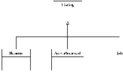
A third connector style is a directed line with a hollow triangle. This is called a generalization. The word generalization in the UML means "inheritance." When we show a generalization relationship between two actors or two use cases, then we are indicating that the child actor or use case is an instance of the base actor or use and something more. Figure 2-4 shows a generalization relationship between two actors and two use cases.
In generalization relationships, the arrow points toward the thing on which we
are expanding. There are a number of ways you can describe this relationshipzyxwvutsrqponmlkjihgfedcbaZYXWVUTSRQPONMLKJIHGFEDCBA
Figure 2-4 A use case diagram showing two generalization relationships between two actors and two use cases.
verbally—which you should know about—but unfortunately, all these synonyms can lead to verbal confusion. The following statements describe the generalization relationships shown in Figure 2-4:
• User is the target, and Employer is the source. • Employer is a User.
• User is the subtype, and Employer is the supertype. • Employer inherits from User.
• User is the parent type, and Employer is the child type. • Employer generalizes User.
(In this list you can substitute the phrase Create a Job Listing everywhere you seezyxwvutsrqponmlkjihgfedcbaZYXWVUTSRQPONMLKJIHGFEDCBA
the word User and substitute the phrase Create Priority Job Listing everywhere you see the word Employer to convey the relationship between the two use cases.) The latter statement, which uses the word generalizes, is the most accurate in the context
Connector Adornments
UML diagrams encourage less text because pictures convey a lot of information through a convenient visual shorthand, but UML diagrams don't eschew text alto-gether. For example, connectors can include text that indicates endpoint multiplicity and text that stereotypes the connector.
Showing Multiplicity
Connectors in general can have multiplicity notations at either end of the connector. The multiplicity notations indicate the possible count of each thing. For example, an asterisk means many. An asterisk next to an actor means that there may be many in-stances of that actor. Although the UML permits notating use case connectors in this way, it isn't that common. You are more likely to see these notational count marks in such diagrams as class diagrams, so I will elaborate on multiplicity in Chapter 3.
Stereotyping Connectors
A more common connector notation is the stereotype. Stereotypes add detail to the relationship between elements in a use case diagram. For example, in Figure 2-3, I introduced the dependency connector. A stereotype can be used to expand on the meaning of the dependency connector.
In the section entitled, "Connector Line Styles," I said that an employer can create a job listing and illustrated this with an employer actor, a "Create Job Listing" use case, and an association connector. However, I also said that the employer must be logged in. When a use case—"Create a Job Listing"—needs the services of another use case—"Log-In"—then the dependent use case is said to include the depended-on use case. (In code, an include relatidepended-onship is implemented as code reuse.)
A stereotype is shown as text between the guillemots (« and » characters). For instance, if we say that "Create a Job Listing" includes "Log-In," then we can depict an include stereotype by annotating the dependency connector as shown in Figure 2-5.
Figure 2-5 An example of an include stereotype—used to depict reuse—on the dependency
Include and extend are important concepts in use case diagrams, so I will expand on these subjects next.zyxwvutsrqponmlkjihgfedcbaZYXWVUTSRQPONMLKJIHGFEDCBA
NOTE Stereotype is a generally useful concept in the UML. The reason for this is that it is permissible to introduce and define your own stereotypes. In this way you can extend the UML.
Including and Extending Use Cases
A dependency relationship between two use cases means that in some way the de-pendent use case needs the depended-on use case. Two commonly used, predefined stereotypes that refine dependencies in use cases are the include and extend stereo-types. Let's take a minute to expand on our introductory comments on include from
the preceding section and introduce extend.zyxwvutsrqponmlkjihgfedcbaZYXWVUTSRQPONMLKJIHGFEDCBA
TIP Visio applies an extends stereotype on the generalization connector to mean
inheritance. Variations between the UML and UML tools exist because the UML is an evolving standard, and the implementation of tools may lag or lead the official definition of the UML.
More on Include Stereotypes
A dependency labeled with the include stereotype means that the dependent use case ultimately is intended to reuse the depended-on use case. The baggage that goes with the include stereotype is that the dependent use case will need the serv-ices of and know something about the realization of the depended-on use, but the opposite is not true. The depended-on use case is a whole and distinct entity that must not depend on the dependent use case. Logging in is a good example. It is clear that we require an employer to log in to create a job listing, but we could log in for other reasons too.
NOTE In an include dependency between use cases, the dependent use case is also
referred to as the base use case, and the depended-on use case is also referred to as the inclusion use case. While base and inclusion may be more precise, they do not seem to be employed in speech commonly yet.
Putting so much meaning into a little word like include is why the UML can con-vey a lot of meaning in a simple diagram, but it is also why UML models can be challenging to create and to read. A real strategy that you can fall back on is to add a
(see "Attaching Notes to Use Case Diagrams" below.) For example, if you want to describe the relationship between "Create a Job Listing" and "Log-In" but aren't sure about which connector or stereotype to use, then you could use a plain associa-tion and a note connected to the connector describing in plain text what you mean. The note can act as a reminder to go back and look up the precise UML later.
Using Extend Stereotypes
The extend stereotype is used to add more detail to a dependency, which means that we are adding more capabilities (see Figure 2-6 for an example). As shown in the figure,
we say that "Log Viewed Listings" extends (and is dependent on) "View Listing."zyxwvutsrqponmlkjihgfedcbaZYXWVUTSRQPONMLKJIHGFEDCBA
NOTE In an extend relationship, the arrow points toward the base use case, and the other end is referred to as the extension use case.
In the preceding section we would not permit an employer to create a job listing without logging in, but the use case log in is indifferent to the use case reusing it. In this section the use case view listing doesn't care that it is being logged; in other words, the logging feature will need to know about the view listing feature, but not vice versa.
A valuable perspective here is who might be interested in the logging. Clearly, the "Job Seeker" probably doesn't care how many times the listing has been viewed, but a prospective employer might be interested in how much traffic his or her listing is generating. Now switch to a different domain for a moment. Suppose that the "Job Seeker" were a home buyer and that a listing were a residential listing. Now both the buyer and seller might be interested in the number of times the property has been viewed. A house that has been on the market for months may have prob-lems. Yet, in both scenarios, the listing is the most important thing, and the number
Figure 2-6 Tracking the number of times a job listing is viewed is an extension of "View
of viewings is secondary. This illustrates the notion of extension use cases as akin to features, and from a marketing perspective, extensions might be items that are
separated into an optional feature pack.zyxwvutsrqponmlkjihgfedcbaZYXWVUTSRQPONMLKJIHGFEDCBA
TIP Consider another alternative as relates to an extension use case. Extension use cases are natural secondary features. If your project has a tight schedule, do the extension use cases last, and if you run out of time, then postpone the extension use cases to a later version.
Include and extend seem somewhat similar, but the best way to keep them straight is to remember that "the include relationship is intended for reusing behavior mod-eled by another use case, whereas the extend relationship is intended for adding parts to existing use cases as well as for modeling optional system services" (Over-gaard and Palmkvist, 2005, p. 79).
Annotating Use Case Diagrams
Consider the job of a court stenographer. Stenographers use those funny steno-graphic typewriters that produce a sort of shorthand gibberish. We can safely assume that if a regular typewriter or word processor were capable of accepting input fast enough to keep up with natural speech, then the stenograph would not have been invented.
Stenographs produce shorthand that is more condensed than speech. The UML is like shorthand for code and text, and UML modeling tools are like stenographs. The idea is that models can be created faster than code or faster than writing tex-tual descriptions. That said, sometimes there is no good substitute for text.
If you find yourself in the predicament that only text seems to resolve—or you aren't sure of the UML—then go ahead and add text. You can add text by document-ing your models with features of most modeldocument-ing tools, by adddocument-ing URL references to more verbose documents, or by adding notes directly in the diagrams themselves. However, if you add too much text, then naturally it will take longer for the model-ing to be complete and may require a greater effort to understand the meanmodel-ing of individual diagrams.
Inserting Notes
The UML is a shorthand for a lot of text and code, but if you need to, you can al-ways add text. Every diagram, including use cases, supports adding textual annotations. Notes are represented as a dog-eared piece of paper with a line attach-ing the textbox to the element beattach-ing annotated (Figure 2-7). Use notes sparattach-ingly
Figure 2-7 A note adding plain text to clarify some aspect of a diagram.
Adding Supporting Documentation
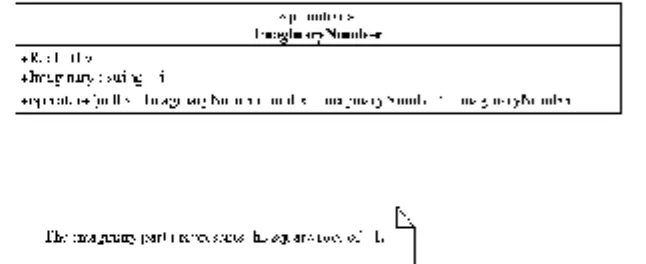
Every modeling tool that I have used—Together, Rose, Rose XDE, Visio, Poseidon for UML, and the one from Cayenne Software—supports model documentation. This documentation usually takes two forms: text that is stored in the model and Uniform Resource Locators (URLs) referencing external documents (Figure 2-8). Exploring the features of your particular tool will uncover these capabilities.
More important is what kind of documentation you should provide. Subjectively, the answer is as little as you can get away with, but use case diagrams generally seem to need the most.
Use case diagrams are pretty basic with their stick figures but are pretty impor-tant because they record the capabilities your system will have. Good information to include with your use case diagrams is
• A pithy paragraph describing how the use begins, including any preconditions • A short paragraph for each of the primary functions
• A short paragraph for each of the secondary functions
• A short paragraph for each of the primary and secondary scenarios, which helps to place the need for the functions in a context
• A paragraph for nonfunctional requirements
• Insertion points where any other dependent use cases are used
Figure 2-8 By double clicking on a model element in Visio, you can add documentation that is stored in the model.
All these elements sound like a lot of work and can be. Remember, though, that use cases are the foundations of analysis, and it is important to document them as care-fully and as thoroughly as you can. It is equally important to note that I used the words pithy and short intentionally. By short, I mean that it is acceptable to have one-sentence paragraphs.
You can use any format you like for documenting your use cases. If you are comfortable with the outline format, it is very easy to create a template outline from the bulleted list. A good practice is to choose a style for your documentation and stick with it.
Let's take a moment to elaborate on the elements—as described in the preceding bulleted list—of use case documentation. Keep in mind that this is not an exact sci-ence, and your use case documentation doesn't have to be perfect.
Documenting a Use Case Using an Outline
You can use free-form text to document a use case, but I find that an outline template suggests the extent of the information and acts as a reminder of the elements needed to document each use case adequately. Here is a template; the
noting that this style of documentation is not part of the UML but is a useful part of modeling.
1. Title
a. Description: Use the use case name here, making it very easy to match use case diagrams with their respective documentation.
b. Example: Maintain Job Listing 2. Use case starts
a. Description: Briefly describe the circumstances leading up to the use case, including preconditions. Leave out implementation details, such as "User Clicks a Hyperlink" or references to forms, controls, or specific implementation details.
b. Example: This use case starts when an employer, employer's agent, or the system wants to create, modify, or remove a job listing.
3. Primary functions
a. Description: Use cases are not necessarily singular. For example, "Manage Job Listing" is a reasonable use case and may include primary functions such as reading and writing to a repository. The key here is to avoid having too few or too many primary functions. If you need a good yardstick, it might be two or three primary functions per use case.
b. Example: "CRUD Job Listing." The primary functions of "Maintain Job Listing" are to create, read, update, and delete the job listing.
4. Secondary functions
a. Description: Secondary functions are like a supporting cast in a play. For example, given a use case "Manage Job Listing," updating, inserting, creating, and deleting a job listing—called CRUD, for create, read, update, and delete—are excellent secondary functions, part of a bigger use case. If you need a yardstick, then two times as many secondary functions as primary functions is good.
b. Examples:
(1) "Expire Job Listing." Thirty days after the listing is made available for viewing, the listing is said to expire. An expired listing is not deleted, but users, with the exception of the listing owner, may no longer view the listing.
(2) "Renew Job Listing." A listing may be extended for an additional
(3) "Make Job Listing a Priority Listing." Any time during the life of a listing, the owner of that listing may elect to promote the listing to a priority listing for a fee prorated by the exhausted portion of the listing period.
(4) "Log Viewed Listing." Each time a listing is viewed, a log entry will be written, recording the date and time the listing was viewed and the Internet Protocol (IP) address of the viewer.
(5) "Examine View Logs." At any time the owner of a listing may view the logged information for his or her listings.
(6) "Automatic Viewed-Log Notification." The owner of a job listing may elect to have view logs sent by e-mail at an interval specified by the owner.
(7) "Pay for Listing." The owner of the listing is required to pay for every listing unless the listing is offered as a promotional giveaway.
5. Primary scenarios
a. Description and example: A scenario is a short story that describes the functions in a context. For instance, given a primary function "Create Job Listing," we might write a scenario such as this: "Mr. Jones' secretary is retiring, and he needs to hire a replacement. Mr. Jones would like a secretary who types 100 words per minute, is willing to work only four hours per day, and is willing to work for $10 per hour. He needs the replacement secretary to start no later than January 15." Consider at least as many primary scenarios as you have primary functions. Also consider a couple of scenario variations for important functions. This will help you to think about your problem in creative ways. It is a useful practice to list the scenarios in approximately the same order as the functions that the scenario describes.
6. Secondary scenarios
7. Nonfunctional requirements
a. Description: Nonfunctional requirements address implicit behaviors, such as how fast something happens or how much data can be transmitted. b. Example: An employer's payment is to be processed while he or she waits
in a period of time no longer than 60 seconds. 8. Use case ends
a. Description: This part describes what it means for the use case to be finished.
b. Example: The use case is over when changes made to the job listing are persisted and the payment has been collected.
How much information you include in the written part of your use cases is really up to you. The UML is silent on this matter, but a process such as the RUP may of-fer you some guidance on content, quantity, and style of text documentation.
As a final note, it is useful to record ideas about functions and scenarios even if you ultimately elect to discard them. For example, we could add a secondary func-tion that states that "The system shall support a semiautomatic renewal of an expiring job listing" supported by the scenario "Mr. Jones' listing for a new secre-tary is about to expire. Mr. Jones is notified by e-mail of the impending expiration. By clicking on a link in the e-mail, Mr. Jones' listing is automatically renewed us-ing the same billus-ing and payment information used with the original listus-ing."
By recording and keeping considered ideas, it is possible to make a record of ideas that were considered but may or may not ever be realized. Keeping a record of possibilities prevents you from rehashing ideas as team members come and go.
Finally, it is useful to insert references to depended-on use cases. Rather than repeating an inclusion use case, for example, simply make a reference to the inclu-sion use case at the point at which it is needed. For example, suppose that paying for a job listing requires an employer to log in. Instead of repeating the "Log-In" use case, we simply make a reference to the "Log-In" use case where it is needed; in this instance we can make a reference to "Log-In" when we talk about paying for the job listing.
Creating Use Case Diagrams
As I mentioned earlier, use cases are design to-do lists. Since another holiday is always just around the corner, a good comparative analogy is that defining use
visit from relatives. For example, you might write down, "Dust living room." Then you decide that your 10-year-old daughter did a good job the last time, so you as-sign the dusting to her. The level of detail is important here because you know—if you have ever dusted—that different kinds of things need different kinds of dusting. Small knickknacks can be dusted with a feather duster. Coffee tables and end tables might need Pledge® and a clean, dry, cloth, and ceiling fans might need the wand and brush on a vacuum cleaner. The key here is the difference between what we
diagram and what we write as part of our use case.zyxwvutsrqponmlkjihgfedcbaZYXWVUTSRQPONMLKJIHGFEDCBA
NOTE You might wonder what dusting has to do with use cases and software.
The first answer is that use case models can be used for things that aren't software, and the second part is that software is found in an increasingly larger number of devices. Suppose that we were defining use cases for a house-cleaning robot; then our dusting rules might be useful. And if you are wondering how probable software for robots might be, then consider the Roomba* cleaner. Roomba is a small robot
that wanders around a room vacuuming up debris, and according to its marketing material, it even knows when to recharge itself. Someone had to define and implement those capabilities.
The use case for dusting in the preceding paragraph would consist of an actor, "Child," an association connector, and a use case "Dust Living Room" (Figure 2-9). The use case diagram itself need not depict all the necessary micro tasks that "Dust Living Room" consists of. For example, "Find Pledge and clean, dry cloth" is a necessary subtask but not really a use case in and of itself. Good use cases mean finding good actors and the right level of detail without convoluting the diagrams.
After we have the use case diagram, we can add supporting information in the model documentation for our use case. Primary functions would include dusting key areas, and secondary functions would include preparation, such as getting the vacu-um cleaner out and finding the Pledge. Adequate scenarios would include addressing specific problem areas, such as dusting picture frames and collectible items. Non-functional requirements might include "Finish dusting before grandparents arrive."
Don't worry about perfect use case diagrams and use case documentation. Use the outline to help you consider the details and use case diagrams to provide you with a good picture of your objectives.
How Many Diagrams Is Enough?
Sufficiency is a tricky problem. If you provide too many use cases, your modeling can go on for months or even years. You can run into the same problem with use
case documentation, too.zyxwvutsrqponmlkjihgfedcbaZYXWVUTSRQPONMLKJIHGFEDCBA
NOTE I consulted on a project for a large department of defense agency. The
agency literally had been working on use cases for almost 2 years with no end in sight. Aside from what seemed like a never-ending project, the domain experts felt that the wrong use cases were being captured or that the use cases had little or no explanatory, practical value. The models were missing the mark. The objective is to capture the essential characteristics of your objective, and use case models are an excellent low-tech way to get nontechnical domain experts involved. Skipping the dialogue-provoking value of use case diagrams is missing half the value of the use case diagrams.
A reasonable baseline is that medium-complexity applications might have be-tween 20 and 50 good use cases. If you know that your problem is moderately complex and you have five use cases, then you may be missing critical functionality. On the other hand, if you have hundreds of use cases, then you may be subdividing practical macro use cases into micro use cases.
Unfortunately, there are no hard and fast rules. Defining the right use cases takes practice and requires good judgment that is acquired over time. To help you begin acquiring some experience, the next subsection demonstrates some actual use case diagrams for www.motown-jobs.com.
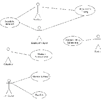
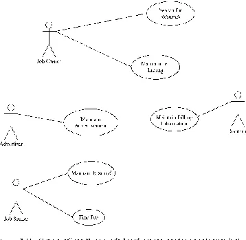
Example Use Case Diagrams
This book is about the UML. Specific text documentation is not part of the UML, so I will limit the examples in this section to creating the use case diagrams. You can use your imagination and the outline in the section entitled "Documenting a Use Case Using an Outline" to practice writing use case descriptions.
Motown-jobs.com is a product of my company, Software Conceptions, Inc. Motown-jobs is a Web site for matching people looking for jobs with people offering
and is implemented in ASP.NET. All this aside, Motown-jobs.com started as an idea whose features were captured as a group of use cases. Because I was building the software for my company, I had to play the role of domain expert—the domain being what it takes to match employers with employees. Since I have been looking for and finding customers for my company for 15 years, I have some experience in this area.
Finding use cases can start with an interview with your domain expert or by making a list. Since I was playing the role of interviewer and interviewee, I simply began with a list of the things I thought Motown-jobs.com would need to offer to be useful. Here is my list:
• Employers or employers' agents will want to post information about jobs being offered.
• Those looking for jobs may want to post a resume that can be viewed by potential employers.
• Employers or employers' agents will want to actively search the Web site for resumes that match the skills needed to fill job openings.
• Those looking for jobs will want to search through jobs listed. • Employers and employers' agents will have to pay for listings and for
<