M Sayuti,Malikussaleh University, Lhokseumawe, Aceh, Indonesia
S Sulaiman, BTHT Baharudin, and MKA Arifin,Universiti Putra Malaysia, Serdang, Selangor, Malaysia r2016 Elsevier Inc. All rights reserved.
1 Background 1
2 Metal Matrix Composites (MMCs) 3
2.1 General 3
2.2 Classification of Composites 5
2.3 Significance of Composites 6
2.4 Preparation of MMCs 6
3 Matrix or Matrices 7
4 Reinforcing Phase/Materials 7
4.1 Factors Affecting Reinforcement 9
4.2 Matrix Interface/Interphase of Matric 9
4.3 Chemical Reaction 10
4.4 Particulate Reinforcement 11
5 Properties of Composites Relevant to Aluminum-Based MMCs 11
5.1 Material Selected for Processing Composites 12
5.1.1 Aluminum−11.8% silicon eutectic alloy 12
5.1.2 Titanium carbide 13
6 Vibrations 13
6.1 Ultrasonic Vibrations 13
6.2 Electro-Magnetic Vibrations 15
6.3 Mechanical Vibration 15
6.4 Mechanical Vibrations Moulding in Casting 16
7 Research Methodology 17
7.1 Preparation of Specimens 19
7.2 Production Methods of Metal Matrix Composite Materials 19
7.2.1 Particulate reinforced metal matrix composite casting fabrication by mechanical vibration 19
7.2.2 Characterization of particulates selected for this research work 19
7.2.3 Melting and casting of particulate reinforced metal matrix composites 19
7.2.4 Preparation of particulate samples and preheating procedure 20
7.3 Testing 20
7.3.1 Tensile testing 20
7.3.2 Hardness test 20
7.3.3 Impact test 20
7.3.4 Metallograpy (optical metallurgical microscopy) 20
7.3.5 Scanning Electron Microscopy 21
7.3.6 Density measurement 21
7.3.7 Thermal properties 21
8 Result and Discussion 21
8.1 Mechanical Properties 21
8.1.1 Tensile test 22
8.1.2 Hardness measurement 23
8.1.3 Fractography 23
8.2 Thermal Conductivity and Diffusivity 23
9 Conclusions 25
References 26
Further Reading 29
Reference Module in Materials Science and Materials Engineering doi:10.1016/B978-0-12-803581-8.04082-0 1
1 Background
Industrial technology is growing at a very rapid rate and consequently there is an increasing demand for new materials. The metal/
non-metal composites represent a class of materials which can withstand high temperature and pressure besides its resistance to radiation effects and chemical reactivity. Metal matrix composites can be produced by many different techniques. One of the most simplest technique is the casting process. Melting metallurgy for the production of metal matrix composite is at present of greater technical importance than powder metallurgy. It is more economical and has the advantage of being able to use well proven casting processes for the production of metal matrix composites. Metal matrix composites (MMCs) are composed of an element of alloy matrix in which a second phase is embedded and distributed to achieve some improvement in its properties. Based on the size, shape and amount of the second phase, the properties of the composite varies. Particulate reinforced composites, often called as discontinuously reinforced metal matrix composites, constitute 5–20% of these new advanced materials. The microstructure of the processed composites influences and has a great effect on the mechanical properties. Generally, increasing the volume or weight fraction of the second phase (reinforcement phase) in the matrix leads to an increased stiffness, yield strength, ultimate tensile strength and other mechanical and physical properties. But the low ductility of particulate reinforced MMCs is the major drawback that prevents their usage as structural components in some applications (Hamoudaet al., 1996;Rizkalla and Abdul- wahed, 1996). Miller and Humphreys (1991a) have carried out a detailed investigation on the strengthening mechanism of composites. They have found that the particle size and its volume fraction in metal matrix composites influence the generation of dislocations due to thermal mismatch as well as the effect influenced by the developed residual and internal stresses. The researchers have predicted that the dislocation density is directly proportional to the volume fraction and also due to the amount of mismatch. The resulting strengthening effect (quench strength) is proportional to the square root of the dislocation density.
Consequently, this effect would be significant forfine particles and for higher volume fractions. Recent studies have shown that the matrix microstructure has a clear effect on the fracture details of the tested specimen.
The mechanical properties and microstructure of aluminum/TiC MMCs have been compared between three processes namely powder processing (PM),flux-casting process, and melting PM material. In cast, particle clustering is more prevalent than PM composites, but in cast MMCs, the degree of clustering reduced by the grain-refining nature of TiC particles while oxidefilms in melting PM material trawled the particles into large clusters. Cast and PM composites have the similarity in stiffness and ductility but strength and ductility significantly reduced when melting the PM material and for all cases, removal of porosity and the break- up of particle clusters by extrusion will enhance composite ductility. Indication by modulus measurements as a function of plastic strain in cast composites consequently of the attainment of intimate contact and strong chemical bonding between the two phases show rate of damage accumulation are lowest thus interfacial bonding is strongest (Kennedy and Wyatt, 2000).
Limmaneevichitr et al. (2009) investigated the effects of mechanical vibration during solidification on the metallurgical structure of hypoeutectic aluminum–silicon A356. Emphasis was placed on the morphological changes of the primary aluminum phase of the as-cast alloy, which was subjected to different levels of mechanical vibration at various values of pouring temperature and solid fraction. They found that the average grain size of the primary phase became relativelyfiner and more globular as the degree of vibration were increased. This suggested that during the solidification process, dendrites that formed normally in the liquid alloy were subsequently disturbed and fragmented by the mechanical vibration applied into the melt. This effect was enhanced when the vibration was applied into an alloy with a larger solid fraction, as was observed with solidification at lower pouring temperatures. In addition to the macrostructure examination, semi-solid properties were also assessed and reported using the Rheocasting Quality Index (RQI). It was shown that the application of mechanical vibration into the A356 melt with adequate solid fraction prior to complete solidification successfully resulted in an as-cast structure featuring semi-solid morphology.
Vibration of a solidifying metal is an old process that was developed early in the last century to assist the casting of aluminum alloys (Mohanty and Gruzleski, 1995). Vibration has been used to help in the promotion of nucleation and thus reducing as-cast grain size, lower susceptibility to cracking and reducing shrinkage porosities which leads to improved features and thereby improved mechanical properties (Shuklaet al., 1980;Sayutiet al., 2014). Usually, a known frequency and amplitude of sinusoidal vibration is applied using a vibration mould during the solidification process. The various types of vibration such as mechanical, ultrasonic or electromagnetic vibration may be applied to the metal through different means. The mechanical vibration may be introduced to the entire mold with the solidifying metal inside of it or it may be limited to the solidifying metal only, while the use electromagnetic vibration can only be applied to the solidifying metal (Numanet al., 2005).
Applying mechanical mould vibration during the solidification process is a very simple technique that does not require complicated procedure neither needs expensive set-up (Sayutiet al., 2012a,b,c). It can be applied for the current existing processes and does not require extensive modifications on the design of the used equipments. It requires less energy as compared to ultrasonic vibration, electromagnetic vibration and semisolid processes and also less expensive. The low energy requirement during the chemical-process made it the most environmentally-friendly process than any other grain refinement technique. There are three practicable methods for application of vibration, namely, mechanical vibration of the whole of the mould, vibration of the liquid solidifying metal, and electromagnetic induction (Kocatepe and Burdett, 2000).
Electromagnetic vibration technique is one of the non-contact methods used to induce vibration inside the solidifying metal.
The vibration is induced by applying an orthogonal static magnet and alternating electricfields. It was reported that the collapse of
the cavities generated by this method was responsible for the grain refinement of the microstructure for Al–7%Si, Al–17%Si, and gray cast iron (Vives, 1988). However, it was also reported that this method is costly and requires tremendous amount of current to be effective (Radjai and Miwa, 2000). On the other hand, application of mechanical vibration during solidification is more commonly used than electromagnetic vibration and another vibration technique due to its simplicity and low cost (Maltaiset al., 2003).
Application of the electromagnetic vibration during the casting led to significant grain refinement that greatly reduced segre- gation in the billet. There was a significant increase in mechanical properties such as the tensile strength, hardness, and fracture elongation of the as-cast AZ80 billet relative to that cast in the absence of the electromagnetic vibration. Microchemical analysis revealed that the application of electromagnetic vibration can be increased concentration of Al and Zn in the Mg matrix (Guoet al., 2006).
However, a review of the literature reveals that the application of mechanical, electromagnetic and ultrasonic vibration has a number of notable effects such as grain refinement, increased density, hardness, ultimate tensile strength, percent elongation, degassing, shrinkage, and the shape, size and distribution of the second phase (Alireza and Miwa, 2000;Eskin, 2001;Swamyet al., 2008). Vibration energy has been applied in many processes within the metallurgical and engineeringfields (Kocatepe, 2007;
Sayuti et al., 2012a,b,c). According to the review by Feng-Wuan and Xiao-Ling (2000), the application of vibration during solidification wasfirst studied in 1800s.
2 Metal Matrix Composites (MMCs)
2.1 General
Metal matrix composites are classified under advanced engineering materials which consists of two or more materials, where tailored properties can be attained by systematic combination of different metallic or non-metallic constituents (Kalpakjian, 1995). Wide varieties of methods are available for metal matrix composites processing including the conventional metal casting process (Amsteadet al., 1987;Sayutiet al., 2012a,b,c). The advantages of composite preparation by casting technology are its near- net shape manufacturing which is a cost-effective and simple method (Chadwick, 1990;Ibrahimet al., 1991). Addition to this, casting processes are employed to manufacture large number of complicated composite casting components at a faster rate required by the aerospace, automobile, transportation, sports and consumer-oriented industries.
Fabrication of discontinuously reinforced Al-based MMCs can be achieved by standardized metallurgical processing methods like powder metallurgy, direct casting, rolling, forging and extrusion. Furthermore the products can be shaped, machined and drilled by using conventional machining facilities. Thus, they can be made available in suitable quantities particularly for auto- motive applications (Seahet al., 2003).
According toEjiofor and Reddy (1999)andHashimet al.(2002a), metal matrix composites (MMC) represent a new generation of engineering materials in which a strong ceramic reinforcement is incorporated into a metal matrix to improve its properties including elastic modulus, specific strength, specific stiffness, wear resistance and corrosion resistance. MMCs combine metallic properties of matrix alloys (ductility and toughness) with ceramic properties of reinforcements (high strength and high modulus), hence leading to a greater strength in shear and compression and higher service-temperature capabilities. Thus, they have sig- nificant scientific, technological and commercial importance. During the last decade, as a result of their improved properties, MMCs are being used extensively for high performance applications such as in automotive industries and more recently in the aircraft engines (Pank and Jackson, 1993;Taufiket al., 2011a).
Aluminum oxide and silicon carbide powders in the form offibers and particulates are commonly used as reinforcements in MMCs and the addition of these reinforcements to aluminum alloys has been subjected to an extensive amount of research work.
Aluminum oxide and silicon carbide reinforced aluminum alloy matrix composites are applied in aircraft industries as engine pistons, cylinder heads and automotives, where the tribological properties of these materials are considered important (Kimet al., 2005;Ponzi, 1992). Incorporation of hard second phase particles in the alloy matrices to produce MMCs has also been reported to be more beneficial and economical due to its high specific strength and corrosion resistance properties. Metal matrix composites are materials that are attractive for a large range of engineering applications (Kok, 2005;Sayutiet al., 2011a,b,c,d,e).
Premkumar and Chu (1995)used an situ process to producefine TiC particulates in a molten aluminum alloy. Introducing carbonaceous gas into an Al melt containing Ti formed TiC particulates. The determination of the carbide volume fraction is by the initial Ti content. For microstructure and property evaluation, the melt containing the carbides was cast and then extruded the microstructure of the in situ processed composites reveals a relatively uniform distribution of TiC particles with an average size of a few microns. The effect of the particles in increasing the yield strength of the composites is more clearly illustrated by comparing the composites (Vf¼0.064) with the unreinforced control sample; the particle-containing alloy has a higher yield strength despite having no stretch prior to ageing. The sub-micron sizedfine particles of TiC that are present in these composites are believed to contribute to strengthening factor, the elastic modulus of the base alloy will increase the by 14%. However, the higher density of TiC results in a 4.5% increase in density of the composite over the base alloy. Thus, on a specific modulus basis (elastic modulus or density), there is an increase ofB9% with the addition of TiC (Vf¼0.064).
Thein situfabrications by SHS reaction of the Al–Ti–C system during aluminum melt casting cause TiC particulates locally reinforced Al–matrix composites (Tong and Fang, 1998). The adiabatic temperature was lowered and ignition delay time was prolonged due to the increasing of Al contents in the green compacts. For 20–40 wt% Al contents in the blends, there are only two phases, TiC anda-Al, can be observed. But in the case of 10 or 50 wt% Al content, the self-heat-sustained (SHS) reaction cannot be initiated. Further X-ray diffraction (XRD) and Differential scanning calorimetric (DSC) studies revealed that the aluminum acts as an intermediate reactant participating in the reaction and not only as diluents. When adding 10 wt% of Al content in the compact, the heat released from the intermediate reaction of Ti–Al is too low to induce the further reaction to form TiC. The interfaces between the Al–matrix and the locally reinforced region with the in-situ formed TiC particulates uniformly distributed showed excellent gradient and bonding. The size of TiC particulates decreased sharply from about 1.0 to 0.2mm with increasing Al contents from 20 to 40 wt% (Songet al., 2008;Taufiket al., 2011b).
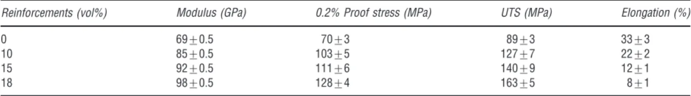
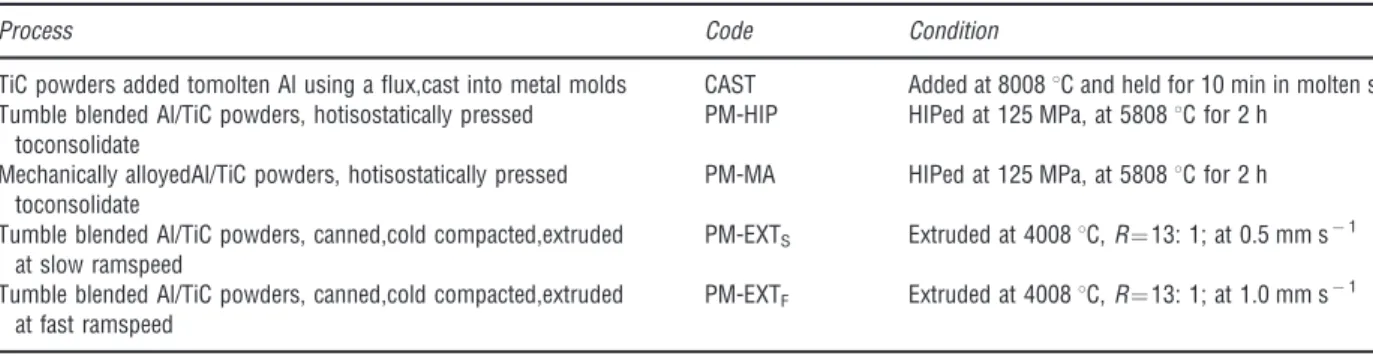
Al–TiC metal matrix composites have been produced by a novel route which enables the nucleation of solid Al on the TiC reinforcing phase to occur and results in line as-cast grain sizes (Tong and Fang, 1998;Taufiket al., 2011c). Solid nucleation results in extensive grain refinement and the engulfment of more particles into the growing primary Al grains during solidification. The 0.2% proof and UTS of CP Al–TiC composites consistently increased as more particles of TiC are added (Table 1). Large proof stress increase suggest that the TiC particles contribute significant strengthening to the composite beyond that due to grain size reduction. The fractional decrease in ductility increases as the strength of the matrix is increased, suggesting that the debonding behavior is stress dominated. Stiffness increases per volume percent of reinforcement added are higher for TiC than that of SiC and Al2O3despite TiC being the least stiffness reinforcing phase. The nucleation of solid on the reinforcing phase results in strong particle–matrix bonding and efficient load transfer thereby maximizing modulus improvements and minimizing decreases in ductility (Kaftelenet al., 2011;Karantzaliset al., 1997). The tensile strength and yield strength increased up to 18% after the formation of TiC in the Al alloy matrix while the hardness increased by up to 20% (Table 2). Thein situformation of TiC particles increases the abrasive and sliding wear resistance (Shyu and Ho, 2006). Methods used for manufacturing the Al–10 vol% TiC composites are summarized in (Table 3;Kennedy and Wyatt, 2001).
Table 1 Mechanical properties of CP Al–TiC extruded composite with various particle additions
Reinforcements (vol%) Modulus (GPa) 0.2% Proof stress (MPa) UTS (MPa) Elongation (%)
0 6970.5 7073 8973 3373
10 8570.5 10375 12777 2272
15 9270.5 11176 14079 1271
18 9870.5 12874 16375 871
Source:Karantzaliset al., 1997.
Table 2 Samples of tensile strength and hardness data
Sample UTS (MPa) YS (MPa) Hardness (HB) Modulus (GPA)
Al–5.1Cu–6.2Ti (alloy) 330712 26276 9474 7874
Composite 400715 29678 11475 9475
Source:Shyu and Ho, 2006.
Table 3 Processing of the Al–10 vol% TiC composites
Process Code Condition
TiC powders added tomolten Al using aflux,cast into metal molds CAST Added at 80081C and held for 10 min in molten state Tumble blended Al/TiC powders, hotisostatically pressed
toconsolidate
PM-HIP HIPed at 125 MPa, at 58081C for 2 h Mechanically alloyedAl/TiC powders, hotisostatically pressed
toconsolidate
PM-MA HIPed at 125 MPa, at 58081C for 2 h Tumble blended Al/TiC powders, canned,cold compacted,extruded
at slow ramspeed
PM-EXTS Extruded at 40081C,R¼13: 1; at 0.5 mm s1 Tumble blended Al/TiC powders, canned,cold compacted,extruded
at fast ramspeed
PM-EXTF Extruded at 40081C,R¼13: 1; at 1.0 mm s1
Source:Kennedy and Wyatt, 2001.
2.2 Classification of Composites
Among the major developments in materials in recent years are composite materials. In fact, composites are now one of the most important classes of engineered materials, because they offer several outstanding properties as compared to conventional mate- rials. The matrix material in a composite may be ceramic based, polymer or metal. Depending on the matrix, composite materials are classified as follows:
a) Metal matrix composites (MMCs) b) Polymer matrix composites (PMCs)
c) Ceramic matrix composites (CMCs)
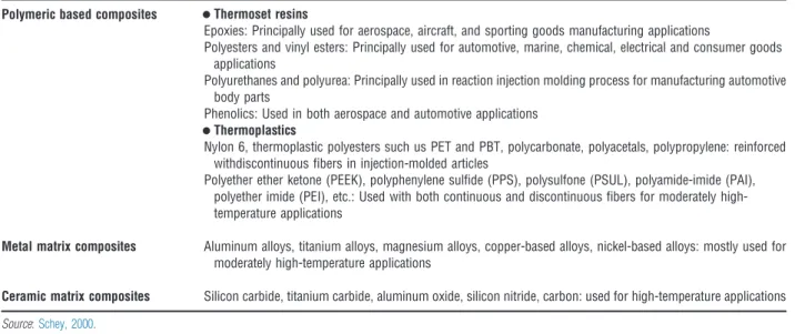
Majority of the composites used commercially are polymer-based matrices. However, metal matrix composites and ceramic matrix composites are attracting great interest in high temperature applications (Feest, 1986). Another class of composite material is based on the cement matrix. Because of their importance in civil engineering structures, considerable effort is being made to develop cement matrix composite with high resistance to cracking (Schey, 2000). The common matrix materials used in composite are listed inTable 4.
Metal matrix composites (MMCs) are composites with a metal or alloy matrix. It has resistance to elevated temperatures, higher elastic modulus, ductility and higher toughness. The limitations are higher density and greater difficulty in processing parts. Matrix materials used in these composites are usually aluminum, magnesium, aluminum–lithium, titanium, copper and super alloys.
Fiber materials used in MMCs are aluminum oxide, graphite, titanium carbide, silicon carbide, boron, tungsten and molybdenum.
The tensile strengths of non-metallicfibers between 2000 and 3000 MPa, with elastic modulus being in the range from 200 to 400 GPa. Because of their lightweight, high specific stiffness and high thermal conductivity, boronfibers in an aluminum matrix have been used for structural tubular supports in the space shuttle orbiter. Metal matrix composites having silicon carbidefibers and a titanium matrix are being used for the skin, stiffeners, beams and frames of the hypersonic aircraft under development.
Other applications are in bicycle frames and sporting goods (Wanget al., 2006). Graphitefibers reinforced in aluminum and magnesium matrices are applied in satellites, missiles and in helicopter structures. Lead matrix composites having graphitefibers are used to make storage-battery plates. Graphitefibers embedded in copper matrix are used to fabricate electrical contacts and bearings. Boronfibers in aluminum are used as compressor blades and structural supports. The samefibers in magnesium are used to make antenna structures. Titanium-boronfiber composites are used as jet-engine fan blades. Molybdenum and tungstenfibers are dispersed in cobalt-base superalloy matrices to make high temperature engine components. Squeeze cast MMCs generally have much better reinforcement distribution than compocast materials. This is due to the fact that a ceramic preform is used contains the desired weight fraction of reinforcement rigidly attached to one another so that movement is inhibited. Consequently, clumping and dendritic segregation are eliminated. Porosity is also minimized, since pressure is used to force the metal into interfiber channels, displacing the gases. Grain size and shape can vary throughout the infiltrated preform because of heatflow patterns. Secondary phases typically form at thefiber-matrix interface, since the lower freezing solute-rich regions diffuse toward thefiber ahead of the solidifying matrix (Surappa, 2003;Sayutiet al., 2011a,b,c,d,e).
Ceramic matrix composites (CMCs) are composites with a ceramic matrix are another important development in engineered materials because of their resistance to corrosive environments and high temperatures. Ceramics are strong and stiff, and they resist high temperatures, but they generally lack toughness. Matrix materials that retain their strength up to 17001C are silicon nitride,
Table 4 List of common matrix materials used in composites application Polymeric based composites
•
Thermoset resinsEpoxies: Principally used for aerospace, aircraft, and sporting goods manufacturing applications
Polyesters and vinyl esters: Principally used for automotive, marine, chemical, electrical and consumer goods applications
Polyurethanes and polyurea: Principally used in reaction injection molding process for manufacturing automotive body parts
Phenolics: Used in both aerospace and automotive applications
•
ThermoplasticsNylon 6, thermoplastic polyesters such us PET and PBT, polycarbonate, polyacetals, polypropylene: reinforced withdiscontinuousfibers in injection-molded articles
Polyether ether ketone (PEEK), polyphenylene sulfide (PPS), polysulfone (PSUL), polyamide-imide (PAI), polyether imide (PEI), etc.: Used with both continuous and discontinuousfibers for moderately high- temperature applications
Metal matrix composites Aluminum alloys, titanium alloys, magnesium alloys, copper-based alloys, nickel-based alloys: mostly used for moderately high-temperature applications
Ceramic matrix composites Silicon carbide, titanium carbide, aluminum oxide, silicon nitride, carbon: used for high-temperature applications Source:Schey, 2000.
silicon carbide, aluminum oxide, and mullite (a compound of aluminum, silicon, and oxygen). Carbon–carbon matrix com- posites retain much of their strength up to 25001C, although they lack oxidation resistance at high temperatures. Carbon–carbon fiber composites are probably the most highly developed of the ceramic matrix composites. These materials are developed mainly used as brake materials for the aerospace industry. Such composites are produced by impregnating shaped carbon or graphite fibers with a carbonized precursor which is subsequently pyrolized, or by chemical vapor decomposition of carbon or graphite.
The resulting materials are strong and light weight, and have excellent high temperature properties, good corrosion resistance, and good thermal shock, electrical, and wear characteristics (Windhorst and Blount, 1997). Their ease of forming makes them useful for wide spread applications. Carbon–carbonfiber CMCs are used as thermal insulation materials, as electrodes, bearings, disks, brake linings, screws and gaskets, nuclear reactor parts, seals, foundry molds, gas turbines, and in pistons for engines. Aerospace applications of such composites are as brakes, rocket nozzles, re-entry systems, turbine blades, rocket exhaust systems, and as heat shields (Kalpakjian, 1995). Fiber materials are usually carbon and aluminum oxide. Various techniques for improving the mechanical properties of ceramic–matrix composites, particularly their toughness, are being investigated. Applications are in jet and automotive engines, deep-sea mining equipment, pressure vessels, structural components, cutting tools, and dies for the extrusion and the drawing of metals (Humphreys, 1987).
2.3 Significance of Composites
Composites technology and science requires loose interaction of various disciplines such as structural analysis and design, mechanics of materials, materials science and process engineering. The tasks of composites research are to investigate the basic characteristics of the constituents and composite materials, develop effective and efficient fabrication procedures, optimize the material for service conditions and understanding their effect on material properties and to determine material properties and predict the structural behavior by analytical procedures and hence to develop effective experimental technique for material characterization, failure analysis and stress analysis (Daniel and Ishai, 1994;Sayutiet al., 2011a,b,c,d,e). An important task is the non-destructive evaluation of material integrity, durability assessment, structural reliability,flaw criticality and life prediction. New types of carbonfibers are being introduced with higher ultimate strains (Ganesh and Chawla, 2005). Thermoplastic matrices are used under certain circumstances because they are tough and have low sensitivity to moisture effects and are more easily amenable to mass production and repair. The use of woven fabric and shortfiber reinforcement is receiving more attention. The structures design and systems capable of operating at elevated temperatures has spurred intensive research in high temperature composites, such as ceramic/matrix, metal/ceramic and carbon/carbon composites. The utilization of conventional and new composite materials is intimately related to fabrication methods development. The manufacturing process is one of the most important stages in controlling the properties and ensuring the quality of the finished product. The technology of composites, although still developing has reached a state of maturity. Prospects for the future are bright for a variety of reasons. Newer high volume applications, such as in the automotive industry, will expand the use of composites greatly.
2.4 Preparation of MMCs
Metal matrix composite materials can be produced by various methods. The focus on the selection of suitable engineering process is to achieve the desired kind, distribution and quantity of the reinforcement components (fibers and particles), the matrix alloy and the applications. By altering the manufacturing method, the processing and the finishing, as well as by the form of the reinforcement components, it is possible to obtain different characteristic profiles, although the same composition and amounts of the components are involved (Girotet al., 2003). The production of a suitable precursor material, the processing to a construction unit or a semi-finished material (profile) and thefinishing treatment must be separated. For cost effective reasons prototypes, reforming procedures are used and with dimensions close to thefinal product which can minimize the mechanicalfinishing of the construction units (Kainer, 2006). In general the following engineering process types are possible:
a) Melting metallurgical processes
b) Hot isostatic pressing of powder mixtures andfiber clutches c) Powder metallurgical processes
d) Further processing of precursor material from the melting metallurgy by thixocasting or -forming, extrusion, forging, cold massive forming or super plastic forming
e) Joining and welding of semi-manufactured products
f) Combined deformation of metal wires (group superconductors).
g) Finishing by machining techniques.
Melting metallurgy for the production of MMCs is at present of greater technical importance than powder metallurgy (Hashim et al., 2001;Kainer, 2006). It is more economical and has the advantage of being able to use well proven casting processes for the production of MMCs. For melting metallurgical processing of composite materials three procedures are mainly used (Kainer, 2006):
a) Compo-casting or melt stirring: Both the terms compo-casting and melt stirring are used for stirring particles into a light alloy melt.
b) Squeeze casting or pressure casting: Squeeze casting is a process by which molten metal solidifies under pressure within closed dies positioned between the plates of a hydraulic press.
c) Gas pressure infiltration: In gas pressure infiltration the melt infiltrates the preform with a gas applied from the outside. A gas that is inert with respect to the matrix is used.
3 Matrix or Matrices
Matrix is the percolating alloy/metal/polymer/plastic/resin/ceramic forming the constituent of a composite in which other con- stituents are embedded. If the matrix is a metal, then it is called as a metal matrix and consecutively polymer matrix, if the matrix is a polymer and so on. In composites, the matrix or matrices have two important functions (Weetonet al., 1988). Firstly, it holds the reinforcement phase in the place. Then, under an applied force, it deforms and distributes the stress to the reinforcement constituents. Sometimes the matrix itself is a key strengthening element. This occurs in certain metal matrix composites. In other cases, a matrix may have to stand up to heat and cold. It may conduct or resist electricity, keep out moisture, or protect against corrosion. It may be chosen for its weight, ease of handling, or any of many other applications. Any solid that can be processed to embed and adherently grip a reinforcing phase is a potential matrix material. Polymers and metals have been very successful in the role and inorganic materials such as glass, Portland cement, plaster, carbon, and silicon have been used as matrix materials with varying success. These later materials remain elastic up to their points of failure and characteristically exhibit low failure strains under tensile loading, but are strong under compression. One important consideration of matrix in composite production is how the constituents of a composite interact during fabrication and/or use (Sulaimanet al., 2008). They should not react chemically or metallurgically in a way that harms. In general, they should not have greatly different coefficients of linear thermal expansion. The area of contiguous contact between the matrix and the reinforcing material is called the interface, which in some ways is analogous to the grain boundaries in monolithic materials. In certain cases, however, the contiguous region is a distinct added phase, called an interphase. Examples are the coating on the glassfibers in reinforced plastics, and the adhesive that bonds the layers of a laminate together. When such an interphase is present, there are two interfaces–one between each surface of the interphase and its adjoining constituent. In still other composites, the surfaces of the dissimilar constituents interact to produce an interphase.
Fabrication methods depend to a great degree on the matrix properties, and how the matrix affects the properties of the rein- forcements. Some of the important matrices used normally in composites processing are metal, polymer, ceramic, glass, and carbon/graphite.
In a composite, matrix is an important phase, which is defined as a continuous one. The important function of a matrix is to hold the reinforcement phase in its embedded place, which act as stress transfer points between the reinforcement and matrix and protect the reinforcement from adverse conditions (Clyne, 1996). It influences the mechanical properties, shear modulus and shear strength and its processing characteristics. Reinforcement phase is the principal load-carrying member in a composite.
Therefore, the orientation, of the reinforcement phase decides the properties of the composite.
4 Reinforcing Phase/Materials
Reinforcement materials must be available in quantity and at an economical rate. Recent researches are directed towards a wider variety of reinforcements for the range of matrix materials being considered, since different reinforcement types and shapes have specific advantages in different matrices (Basavarajappaet al., 2004). It is to be noted that the composite properties depend not only on the properties of the constituents, but also on the chemical interaction between them and on the difference in their thermal expansion coefficients, which both depend on the processing route. In high temperature composites, the problem is more complicated due to enhanced chemical reactions and phase instability at both processing and application temperature. Rein- forcement phases in MMCs are embedded in the form of continuous reinforcement or discontinuous reinforcement in the matrix material. Continuous reinforcement phase is continuous in at least one direction through the composite. Continuousfibers or percolating open-celled foam is suitable examples of the continuous reinforcement phase type. Continuousfibers are cylindrical ingredient material produced continuously to form an essentially endless reinforcement in the composite, usually delivered on bobbins of multifilament tows, each tow consisting of many individualfibers of diameters typically in the range of 3–30mm.
According to the production process, suchfibers are usually coated by a polymeric sizing and the tows may be slightly twisted.
They are typically designated by a brand name, the number offibers per tow and a symbol of the applied sizing. Monofilaments are endless reinforcement as continuousfibers, except for a larger diameter, typically greater than 100mm. Monofilaments are generally produced by deposition onto a corefiber and are delivered as individualfibers instead of tows. Discontinuous rein- forcement is a non-percolating constituent of a composite, taking the form of individual elements embedded in the matrix constituent as particulates, shortfibers, and whiskers. Preforms produced from discontinuous reinforcements that are mechanically
stabilized by a binder or by cold compaction are still considered discontinuous reinforcements (Attia, 2001). Particulates are roughly equiaxed reinforcement, usually of aspect ratio less than about 5. They can be both mono- and polycrystalline, can take various shapes like spherical, angular, and plate-like and are typically greater than 1mm in diameter. Dispersoids are the same as particulates, except that the diameter is less than 1mm, hence, being capable of providing strengthening. Platelets areflat rein- forcements of an aspect ratio (diameter to thickness) greater than two. Platelets of an aspect ratio less than 5 can be considered as a type of particulate. Shortfibers are cylindrical reinforcements with a ratio of length to diameter greater than 5, but typically greater than 100, and with a diameter typically greater than 1mm. Whiskers are elongated single crystals, typically produced with a length to diameter ratio greater than 10 and with a diameter typically less than 1mm. Several refractory reinforcing phases are used in composites processing. They are refractory metals, carbides, nitrides, borides, oxides, sulfides, intermetallics, silicides, and silicates.
Since refractory metal compounds such as carbides, nitrides, borides, silicide and oxides are known to be extremely hard and to keep their strength at elevated temperatures (Ibrahimet al., 1991). There are different considerations in choosing reinforcement.
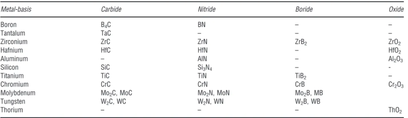
The selecting criteria must be set up based on their properties, which are mainly influenced by the chemical composition, melting point, density, volume shrinkage, shape and size, crystal structure, free energy of formation, Young’s modulus, diffusivity and finally, availability, ease of production and use. A large number of different oxides, carbides, nitrides and borides are suitable for reinforcement; an overview is given inTable 5(Kainer, 2006). The following have proved technically and economically interesting:
silicon and boron carbides, aluminum oxide, aluminum and boron nitrides and titanium boride. A summary of the properties of these hard materials is given inTable 6.
The reinforcing phase may be a particulate or afiber, continuous type or discontinuous type. Some of the important parti- culates normally reinforced in composite materials are titanium carbide, tungsten carbide, silicon nitride, aluminum silicate, quartz, silicon carbide, graphite,fly ash, alumina, glassfibers, titanium boride, etc. The reinforcement second phase material is selected depending on the application during the processing of composites (Clyne, 1996). The reinforcement phase is in the form of particulates andfibers generally. The size of the particulate is expressed in microns, micrometer. However, the discontinuous fiber is defined by a term called as‘Aspect Ratio’. It is expressed as the ratio of length to the diameter of thefiber. To improve the wettabilty with the liquid alloy or metal matrix material, the reinforcement phase is always preheated (Adamset al., 2003;Sayuti et al., 2011a,b,c,d,e). Some potential composite-reinforcement materials and their applications are listed inTable 7.
Table 5 Potential particle for metal reinforcement
Metal-basis Carbide Nitride Boride Oxide
Boron B4C BN – –
Tantalum TaC – – –
Zirconium ZrC ZrN ZrB2 ZrO2
Hafnium HfC HfN – HfO2
Aluminum – AlN – Al2O3
Silicon SiC Si3N4 – -
Titanium TiC TiN TiB2 –
Chromium CrC CrN CrB Cr2O3
Molybdenum Mo2C, MoC Mo2N, MoN Mo2B, MB
Tungsten W2C, WC W2N, WN W2B, WB
Thorium – – – ThO2
Source:Kainer, 2006.
Table 6 Properties of various particles for reinforcement of metals
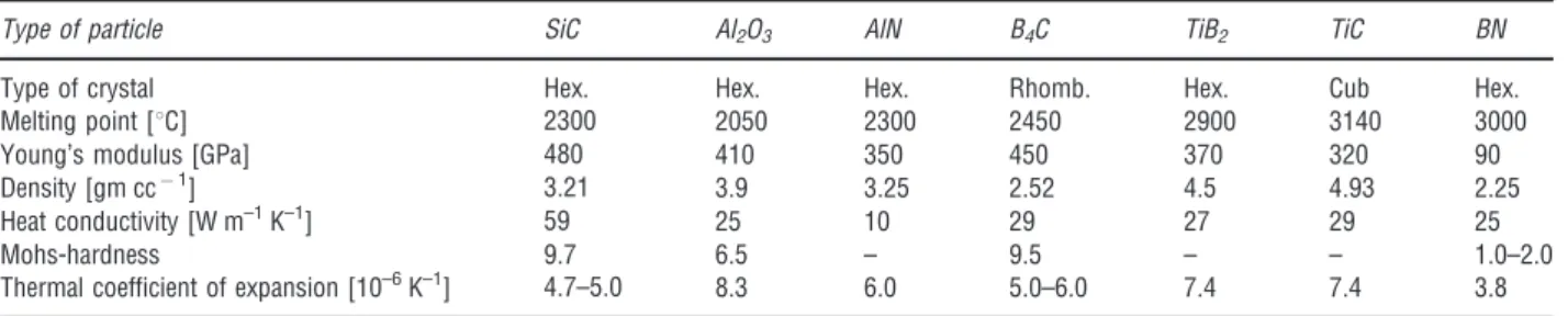
Type of particle SiC Al2O3 AlN B4C TiB2 TiC BN
Type of crystal Hex. Hex. Hex. Rhomb. Hex. Cub Hex.
Melting point [1C] 2300 2050 2300 2450 2900 3140 3000
Young’s modulus [GPa] 480 410 350 450 370 320 90
Density [gm cc1] 3.21 3.9 3.25 2.52 4.5 4.93 2.25
Heat conductivity [W m–1K–1] 59 25 10 29 27 29 25
Mohs-hardness 9.7 6.5 – 9.5 – – 1.0–2.0
Thermal coefficient of expansion [10–6K–1] 4.7–5.0 8.3 6.0 5.0–6.0 7.4 7.4 3.8
Source:Kainer, 2006.
4.1 Factors Affecting Reinforcement
The interface between the matrix and the reinforcement plays an important role for deciding and explaining the toughening mechanism in the metal matrix composites. The interface between the matrix and the reinforcement should be organized in such a way that the bond in between the interface and the matrix should not be either strong or weak (Singhet al., 2001).
4.2 Matrix Interface/Interphase of Matric
Interfaces are considered particularly important in the mechanical behavior of MMCs since they control the load transfer between the matrix and the reinforcement. Their nature depends on the matrix composition, the nature of the reinforcement, the fabrication method and the thermal treatments of the composite. For particular matrix/reinforcement associations and especially with liquid processing routes, reactions can occur which change the composition of the matrix and lead to interfacial reaction products, thus changing the mechanical behavior of the composites. The interfacial phenomena in MMC have been surveyed by several authors.
Considering physical and chemical properties of both the matrix and the reinforcing material, the actual strength and toughness desired for thefinal MMCs, a compromise has to be achieved balancing often several conflicting requirements. A weak interface will lead to crack propagation following the interface, while a strong matrix associated with a strong interface will reveal cracks across both the matrix and the reinforcements. If however the matrix is weak in comparison with the interface and the particle strength, the failure will propagate through the matrix itself. The wettability of the reinforcement material by the liquid metallic matrix plays a major role in the bond formation. It mainly depends on heat of formation, electronic structure of the reinforcement and the molten metal temperature, time, atmosphere, roughness and crystallography of the reinforcement. Similarity between metallic bond and covalent bond is reflected in some metal, like titanium carbide and zirconium carbide which are more easily wetted than strong ionic bonds found in ceramics such as alumina that remains poorly wetted. Surface roughness of the reinforced material improves the mechanical interlocking at the interface, though the contribution of the resulting interfacial shear strength is secondary com- pared to chemical bonding. Large differences in thermal expansion coefficient between the matrix and the reinforcement should be avoided as they can include internal matrix stresses and ultimately give rise to interfacial failures. From a purely thermo dynamical point of view, a comparison of free enthalpy of formation at various temperatures shows that many metals in the liquid state are reactive toward the reinforcing materials in particular oxides or carbides. Though thermodynamically favoured, some reactions are however not observed and practically the kinetics of these reactions has to be considered in conjunction with thermodynamic data in order to evaluate the real potential of the reactions. The consequences of such interfacial reactions are the chemical degradation of the reinforcing material associated with a decrease of its mechanical properties, the formation of brittle reaction products at the interface, as well as the release of elements initially part of the reinforcing material toward the matrix may generate inopportune metallurgical phases at the vicinity of the reinforcing materials. Moreover in the case of alloyed matrices, the selective reactivity and depletion of given elements from the alloy can generate compositional gradients in the matrix and may therefore alter its properties close to the interface. Though a moderate reaction may improve the composite bonding, extended reactions usually ruin the reinforcing material. The relation between interfacial reactions and interface strength depends on the materials. The elaboration of MMC requires often a very short solidification time to avoid excess interfacial reaction. During the cooling process, differences in thermal capacity and thermal conductivity between the reinforcing material and the matrix induce localized temperature gradients.
Solidification of the metallic matrix is believed to be generally a directional outward process, starting from the inside of the metallic matrix while ending at the reinforcing material surface. Finally, the processing type and the parameters have to be selected and adjusted to a particular MMC system. Metals are generally more reactive in the liquid rather than in the solid state. Consequently, shorter processing time, that is, short contact time between the liquid metal and the reinforcement can limit the extent of interfacial reactions. The study of reinforcement and matrix bonding is important in composite matrix structure, which has been described by Gregolinet al.(2002). While the load is acting on the composite, it has been distributed to the matrix and the reinforcement phase Table 7 Some potential composite-reinforcement phase/materials and applications
Metal base Carbides Nitrides Borides Oxides Applications
Boron B4C BN _ _ Aerospace, nuclear
Tantalum TaC TaN TaB2 _ Aerospace
Zirconium ZrC ZrN ZrB2 ZrO2 Aerospace, automotive, nuclear
Hafnium HfC HfN HfB HfO2 Aerospace, nuclear
Aluminum _ AlN _ Al2O3 Automotive, metal working
Silicon SiC Si3N4 _ _ Automotive, aerospace, metal working
Titanium TiC TiN TiB2 _ Aerospace
Chromium CrC _ CrB2 CrO2 Aerospace, Automotive
Molybdenum MoC _ MoB _ Aerospace, automotive
Tungsten WC – WB – Metal working
Thorium ThC2 ThN – ThO2 Aerospace
Source:El-Mahallawy and Taha, 1993.
through the matrix interface. The reinforcement is effective in strengthening the matrix only if a strong interfacial bond exists between them. The interfacial properties also influence the resistance to crack propagation in a composite and therefore its fracture toughness (Dusza and Sajgalik, 1995). The two most important energy-absorbing failure mechanisms in a composite are debonding and particle pull out at the particle matrix interface. If the interface between the matrix and reinforcement debonds, then the crack propagation is interrupted by the debonding process and instead of moving through the particle, the crack move along the particle surface allowing the particle to carry higher load (El-Mahallawy and Taha, 1993).
4.3 Chemical Reaction
The Al and TiC reaction has not yet been clearly established. Because of two materials are not in equilibrium when in contact Al between TiC. There are three reactions of Al and TiC have been proposed (Daniel and Ishai, 1994;Sahoo and Koczak, 1991).
4Al 1ð Þ þ3TiC sð Þ ¼Al4C3ð Þ þs 3Ti 1ð Þ ½1
or; AlTiþCH4¼Al4C3ðsÞ þAlþTiC ½2
7Alþ3TiC¼Al4C3þ3TiAl ½3
13Alþ3TiC¼Al4C3þ3TiAl3 ½4
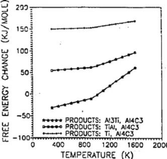
The free energy change at different temperatures for these three reactions between Al and TiC are shown inFigure 1. Note that only the reaction of Al4C3 form and TiAl3 (Reaction [4]) is feasible and this is only true for temperatures below 7501C, approximately. Other has quote similar free energies for these reactions.
During Al/TiC composites processing, a number of phases have been reported. The Al4C3 and TiAl3 is a most common presence, which would be understandable according to eqn [4]. This include TiAl (probably through the reaction eqn [3] to be thermodynamically unstable) and ternary compounds such as Ti2AlC (H phase) and the Perovskite phase Ti3AlC. These latter two may form through secondary reaction (Daniel and Ishai, 1994):
TiAlþTiC¼Ti2AlC ½5
Ti3Al þ TiC ¼Ti3AlC þ Ti ½6
The formation of these phases, especially at room temperature, is not yet fully understood since thermodynamic data is not available for such compounds. Therefore eqns [5] and [6] are only speculative.
Figure 1 The free energy vs. temperature (Daniel and Ishai, 1994).
4.4 Particulate Reinforcement
The improvement in toughness due to the particulate reinforcement depends on the residual stresses surrounding the particles, the weight fraction of the particles, size and shape of the particles (Hudaet al., 1993;Suery and Esperance, 1993). Particles can be spherical, disk-shaped, rod shaped, and plate shaped. Each particle forces the crack to go out of plane, and can force the crack to deflect in more than one direction and thus increase the fracture surface energy (Gogopsi, 1994). Plate and rod shaped particles can increase the composite toughness by another mechanism called as‘pullout’and‘bridging’. The residual stress around the particles results from thermal expansion mismatch between the particles and the matrix, which helps to resist the crack propa- gation. The term‘particulates’is used to distinguish these materials from particle and referred as a large, diverge group of materials that consists of minute particles. The second phase particle can produce small but significant increase in toughness and conse- quently increases its strength through crack deflection processes. The particles, sometimes given a proprietary coating can be used for improving strength. When compared to whiskers-reinforcement systems, particle reinforcement systems have less processing difficulties and should permit to add higher weight fractions of the reinforcing phase. The orientation of particles appears asflat plates (Matthew and Rawlings, 1999;Pardoet al., 2005).
Reinforcements for metal matrix composites have a manifold demand profile, which is determined by production and pro- cessing and by the matrix system of the composite material. The following demands are generally applicable (Hashimet al., 1999;
Kainer, 2006):
i. Low density
ii. Mechanical compatibility (a thermal expansion coefficient which is low but adapted to the matrix) iii. Chemical compatibility
iv. Thermal stability v. High Young’s modulus
vi. High compression and tensile strength vii. Good processability and
viii. Economic efficienncy.
5 Properties of Composites Relevant to Aluminum-Based MMCs
Aluminum is the most popular matrix for the metal matrix composites (MMCs). The aluminum alloys are quite attractive due to their low density, their good corrosion resistance, their capability to be strengthened by precipitation, their high vibration damping capacity and high thermal and electrical conductivity (Sayutiet al., 2011a,b,c,d,e; Surayaet al., 2011). Aluminum matrix com- posites have been used since the 1920s and are now used in electronic packaging, sporting goods, armors and automotive industries. They offer a large variety of mechanical properties depending on the chemical composition of the aluminum matrix.
They are usually reinforced by aluminum oxide, silicon dioxide, silicon carbide, carbon, boron nitride, graphite, boron, boron carbide etc. and aluminum nitride is also dispersed in the matrix. In the 1980s, transportation industries began to develop discontinuously reinforced aluminum matrix composites. They are very attractive for their isotropic mechanical properties and their low costs. The properties of composites of MMCs are inevitably a compromise between the properties of the matrix and reinforcement phases (Doel and Bowen, 1996). It is clear that the composition and properties of the matrix phase affect the properties of the composite both directly, by normal strengthening mechanisms, and indirectly, by chemical interactions at the reinforcement/matrix interface (Kalpakjian, 1995). Aluminum based composites, reinforced with ceramic particles, offer improvements over the matrix alloy: an elastic modulus higher than that of aluminum has a value of 70 GPa, a coefficient of thermal expansion which is closer to that of steel or of cast iron, a greater resistance to wear and an improvement in rupture stress especially at higher temperatures and possibly improved resistance to thermal fatigue (Ejiofor and Reddy, 1997). In addition to the benefits listed above, there are decreases in elongation to failure and fracture toughness. Fortunately, the introduction of alu- minum–silicon/ceramic composites seems to provide a good basis for manufacturing pistons which may be expected to meet the demands to withstand higher cylinder pressures, increased fuel injection rates and higher operating temperatures. Increasing the weight fraction percentage of silicon carbide particulates addition in the LM6 alloy matrix has increased ultimate tensile stresses, modulus, yield but a reduced strain to fracture (Chawla and Shen, 2001). However, it is seen that that silicon content of the matrix has a dominant effect in reducing the fracture strain more than the increase in silicon carbide particulate addition.
The strength of particulate MMCs has been addressed by both a continuum mechanics, based upon shear-lag-type models, Eshelby’s equivalent inclusion technique,finite elements methods and a dislocation mechanics approach. However, the alumi- num–12% silicon materials have relatively higher fatigue strength compared with those contained 5% silicon. Endurance limit based on 107cycles decreases with silicon carbide addition in the LM6 alloy–silicon carbide particulate composites. In the case of sillimanite particulate reinforced aluminum matrix composites, the hardness of the matrix alloy has increased from 57 to 85 HV due to the dispersion of the sillimanite particles in the matrix. This may be attributed to the significantly higher hardness value, 650 HV of the sillimanite particles, and the matrix becomes plastically constrained due to thermal residual stress in the presence of the sillimanite particles (Singhet al., 2001). Many of the properties of particulate reinforced metal matrix composites like strength,
ductility, stiffness, etc. fall below the predicted values by the rule of mixtures. For 10% weight fraction addition of sillimanite particles in the aluminum–silicon alloy, the ultimate tensile strength has decreased marginally from 132 to 121 MPa and per- centage elongation has decreased significantly from 2.25 to 1.42%. Same properties results are found and similar to those of other aluminum–silicon alloy composites dispersed with other hard particles. This is primarily due to the mechanical type of bonding and ineffective load transfer from the matrix to the reinforcement (Daiet al., 2001).
Boron-reinforced aluminum MMC combines the outstanding strength, low density and stiffness of the boron fiber with fabrication and engineering reliability of an aluminum alloy. The overall improvement in modulus to density ratio of the boron fiber is almost six times that of any of the standard engineering materials, including steel, molybdenum, aluminum and mag- nesium. This is advantageous in the prevention of micro buckling offibers in the matrix under compression. Other important physical and mechanical properties of boron/aluminum composites include ductility, high electrical and thermal conductivity, toughness, non-flammability and ability to be coated, formable and joinable through heat treatment (Hu and Yan, 2011).
The graphite/aluminum composites are very attractive because the composite can be designed with the coefficient of thermal expansion approaching zero. The extremely high stiffness of the graphitefibers makes possible a composite that is ideal for applications where precise pointing and tracking are required. These are well suited for start strut assemblies, especially in space structures that are subject to a wide range of temperature across them. Graphite/aluminum is also applicable for stable instrument platforms, electronics, and thermal control devices such as heat pipes. Stiffness to weight ratio is high since the material is 30 percent stiffer than aluminum with no thermal expansion. Dispersion of graphite particles in aluminum–silicon alloy provides the alloy with antifriction properties, good wear properties such as wear rate, P–V limits, seizure resistance, high damping char- acteristics, and good machinability. As a result, most developmental activities on this class of composites have focused more on their microstructure and tribological characteristics than on mechanical properties (Vijayaram, 2006;Sayutiet al., 2011a,b,c,d,e;
Taufiket al., 2011d).
The alumina dispersoid is thermodynamically stable in molten aluminum alloy containing no magnesium. As a result, wetting and bonding is achieved by changing the surface chemistry of the dispersoids or by alloy additions such as magnesium and nickel to the matrix melt. Additions of 3% weight fraction of alumina having a size of 100mm to the aluminum alloy matrix has increased the hardness from 27BHN to 37BHN and the ultimate tensile strength from 75 to 93 MPa, it reduced the ultimate tensile strength of aluminum–8% silicon alloy from 157 to 123 MPa. Zircon, which is relatively heavier than many ceramic particles, requires little or no vortex before introduction into the alloy melt. Hardness and abrasive wear resistance, ultimate tensile strength, and yield strength are increased with the amount of zircon addition in the aluminum matrix while the percentage of elongation is decreased (Warren and Hunt, 2000).
Fly ash reinforced aluminum alloy matrix composites processed by casting vortex-mixing process showed better abrasion resistance and wear resistance than the monolithic aluminum and aluminum alloys. Specific abrasive wear rate of aluminum alloy with 3% weight fraction offly ash is decreased with increasing load and increasing sliding velocity. The aluminum–alloy with 3%
weight fraction offly ash showed better resistance than the base alloy up to 24 N. Specific abrasive wear rates of the composite containing 3%fly ash decreased with the decreasing size of the abraded particles. Friction coefficients of thefly ash composites decreased with increasing time, load and size of the abrading particles. Fly ash alloy aluminum composites are significantly lighter when compared to steel (Jamasriet al., 2010).
5.1 Material Selected for Processing Composites
Materials used in this research project are aluminum–11.8% silicon alloy, and titanium carbide particulate. They are added in different percentages on weight fraction basis and hence to produce different types of particulate reinforced metal matrix com- posites. Mechanical vibration moulding is used during solidification of cast-composites. The economics of the composite slurry casting process is strongly influenced by the viscosity of the molten matrix (Mortensenet al., 1989). Sand mould are used to pour the composite slurry mixture in the slab shape molded cavities to make the composite castings.
5.1.1 Aluminum–11.8% silicon eutectic alloy
The matrix material used in this research work is aluminum–silicon alloy (Metals Handbook, ASM, 1973). It is based on British specifications that conforms to BS 1490–1988 as Aluminum–11.8% silicon alloy. It is actually a eutectic alloy having the lowest melting point that can be seen from the Aluminum–Silicon phase diagram. Aluminum–11.8% silicon alloy is corrosion resistant with average durability and strength, and possess high impact strength and ductility (Hells and Brandes, 1976; Pio,2005). The chemical composition of the melted alloy is analyzed by a spectrometer and the various constituents present is shown inTable 8 (Woodward, 1989).
The chemical composition of aluminum–11.8% silicon alloy is about 85.95% of aluminum, 11–13% of silicon. The mechanical, thermal and electrical property of aluminum–11.8% silicon alloy is shown inTable 9(Kaye and Laby, 1996).
The common composite material candidates are aluminum, lithium, magnesium, magnesium and titanium alloy composites.
They are processed as different component parts aimed from improving the limited properties of conventional aluminum
properties like weight reduction, elevated temperature for engine components and highly loaded engines, wear resistance for brake disks, drums, and cylinder blocks and modulus of elasticity for calipers (Ejiofor and Reddy, 1997).
5.1.2 Titanium carbide
Titanium carbide is a ceramic material normally used for aerospace applications. The molecular weight of titanium carbide is 59.89, its melting point is 31401C, and boiling point is 48201C. The density of tungsten carbide is 4.93 gm cc1and Mohs hardness at 201C is 3200 kg m2. The crystal structure of tungsten carbide is of cubic type. The electrical resistivity of titanium carbide ranges from 180 to 250mOcm (Neeley and Bertone, 2000).
6 Vibrations
In general, vibration is the motion of the particles of an elastic body or medium in alternately opposite direction of equilibrium, periodically in time. Pillai et al. (2004)have published an extensive survey of different techniques of vibration used during solidification and their effect on thefinal structure.
6.1 Ultrasonic Vibrations
Eskin (1994) summarized the effect of ultrasonic vibration treatment on light alloy materials. Work of various researchers demonstrated that ultrasonic vibrations method can be used for cavitations,finefiltration of melts (the USFIRALS process), melt Table 8 Composition of Aluminum–11.8% silicon alloy expressed in percentage
Al Cu Mg Si Fe Mn Ni Zn Lead Tin Titanium Others
85.95 0.2 0.1 11.8 0.5 0.5 0.1 0.1 0.1 0.05 0.2 0.2
Source:Woodward, 1989.
Table 9 Mechanical, thermal and electrical properties of Aluminum–11.8% silicon alloy
Values Physical properties
Density (gm cc1) 2.66
Mechanical properties
Tensile strength, ultimate (MPa) 290
Tensile strength, yield (MPa) 131
%Elongation break (%) 3.5
Poisson’s ratio 0.33
Fatigue strength (MPa) 130
Machinability 30
Shear strength (MPa) 170
Hardness (BHN) 50
Modulus of elasticity,E(N mm2) 71 000 Thermal properties
CTE, linear 201C (mm m11C1) 20.4 CTE, linear 2501C (mm m11C1) 22.4
Heat capacity (J g11C1) 0.963
Heat of fusion (J g1) 389
Thermal conductivity (W m1K1) 155
Melting point (1C) 574
Solidus (1C) 574
Liquidus (1C) 582
Electrical properties
Electrical resistivity (Ocm1) 0.000 004 4 Source:Kaye and Laby, 1996.
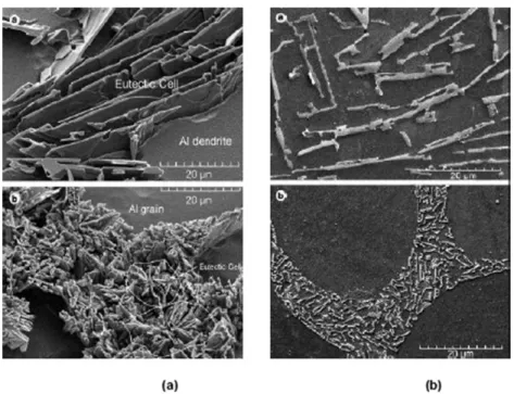
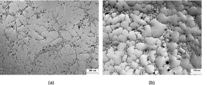
degassing, spatial solidification, non-dendritic solidification, improved semi-solid deformation and for the production of alu- minum alloys with low-solubility component (Eskin and Eskin, 2003). The ultrasonic treatment is an effective method for degassing aluminum melts (Xinbaoet al., 2008;Xuet al., 2004). Also the ultrasonic vibrations could be used to refine eutectic silicon in hypoeutectic Al–Si alloys (Jianet al., 2006).Figure 2shows the effect of ultrasonic vibrations on the morphology of eutectic Si (Jianet al., 2006) andFigure 3shows the effect of ultrasonic vibration on the grain structure of A356 alloy (Jianet al., 2005).
Although ultrasonic vibrations technique have shown favorable effects on the solidification characteristics of aluminum alloy, its commercial applications are constrained mainly because of the difficulties to use of ultrasonic instruments on the foundryfloor (Jianet al., 2005).
Gaoet al.(2009)investigated the effects of ultrasonic vibration on solidification process of AZ91 alloy with different powers from 0 to 700 W. Without subject to ultrasonic vibration (0 W of ultrasonic power), the dendrites were coarse and large. Globular grains were obtained in AZ91 alloy subjected to high intensity ultrasonic vibration. The grain size of AZ91 was decreased gradually from 202 to 146mm with increasing ultrasonic vibration power. The ultimate tensile strength was increased from 145 to 195 MPa and elongation to fracture from 2.3 to 5.2% correspondingly with increasing ultrasonic vibration power.
Hiedemann (1954)studied three different techniques to induce mechanical vibration such as mechanical vibrator, electro- mechanical transducers and electrodynamical excitation. The researcher found that sonic and ultrasonic treatment has a clear effect on variety of metallurgical properties such as reduction of degassing of melts, grain size and dispersion of substances in melts.
Summary of the influence of vibration is listed inTable 10.
Figure 2 Eutectic Si Morphology (a) without ultrasonic vibration and (b) with ultrasonic vibration (Jianet al., 2006).
Figure 3 Effect of ultrasonic vibrations on microstructure of A356 alloy, without ultrasonic vibration (a) and (b) with ultrasonic vibrations (Jian et al., 2005).
6.2 Electro-Magnetic Vibrations
As the name suggests, electromagnetic vibrations typically involve two different forcefields, namely an alternating electricfield and a stationary magneticfield. If a stationary magneticfield with a magneticflux density‘B’and an alternating electricalfield with a frequency‘f’and current density‘J’is applied to a melt, then an electromagnetic vibrating body force with a density‘F’is induced inside the melt, where F¼JB. This force‘F’sets the particles inside the melt into vibration motion with a frequency equal to the frequency of the alternating electricalfield, and the particlesvibrating perpendicular to the plane of vector J and B (Alireza and Miwa, 2000). An effect of this electromagnetic force is formed inside the melt due to the applied magnetic force and the induced force. This force is partly rotational and stirs the melt.Figure 4illustrates the relationship between these forces.
Applied low frequency electromagnetic vibration could be used to grain refinement, to avoid cracks, to eliminate micro segregation and improve the as-cast surface quality of alloys.Paket al. (2005, 2007) studied that electromagnetic vibrations reduced the grain size of primary silicon. They attributed this phenomenon to the collision of primary Si particles with one another. Yoshikiet al.(2004)imposed electromagnetic vibrations on an Al–7 wt% Si alloy and found that with an increasing frequency of the vibrations, the primary a-Al dendrites approached a globular shape of about 25mm in size.Mizutaniet al.(2006) also found that in Al–17 wt% Si, the primary Si particles were refined to 5mm at a frequency nearing 1 kHz. The level of grain refinement increases with the frequency of vibration. They attributed this phenomenon to collapsed dendrite arms due to micro- explosion and stirring that took place in the melt. Various researchers includingHernández and Sokolowski (2005)andVives (1996)reported that electromagnetic vibrations can improve the surface quality of the castings, refined primary and eutectic Si, refined and uniform grain structure.
6.3 Mechanical Vibration
In this technique, the molding is set into vibration by means of a vibration source that is mechanically operated. Although the use of mechanical vibrations allows limited degrees of freedom to the operator, it is the most promising technique of applying vibrations to solidifying melts. This technique is very simple and a rugged equipment that is needed for inducing vibrations.
Vibrations: A periodic motion of the particles of an elastic body or medium in alternately opposite directions from the equilibrium position when that equilibrium is disturbed.
Amplitude: The severity of vibration.
– Peak-to-peak – Zero-to-zero
Table 10 Summary of the effect of vibration on metallurgical properties of materials
Alloy Vibration condition Metallurgical properties Mechanical properties Other remark
Sn–Zn eutectic Sonic Finer zinc needles – –
Sn, Zn and Al 600–4500 kHz Dendritic structure – –
Fe–zinc 9 kHz Increased Fe solution in Zn – –
Sb, Cd, Silumin, Duralumin
10 kHz Smaller grain size Increase hardness, Sb 52%,
Duralmin 23%
Reduced brittleness of Sn Mg–45AlMg–12%Al 50 Hz, 280 kHz True eutectic instead of irregular
structure.
– 50 Hz give more
refinement Wood’s alloys 50 Hz, 9 kHz, 284 kHz
(1.4 W cm2)
Shortening of needles – More efficient with high
intensity Source:Hiedemann, 1954.
Figure 4 Force vibration direction F developed by the alternating electricfield J and the stationary magneticfield B interaction (Alireza and Miwa, 2000).
– Average value
– Root means square value
For the purposes of this work, all values of amplitude are represented in the form of Root Mean Square Value (RMS).
Frequency:The number of cycles that a system will perform in a unit time. It is usually measured in Hertz (Hz).
6.4 Mechanical Vibrations Moulding in Casting
Campbell (1981)reported that the mechanical vibration during solidification causes improvement in mechanical, physical and corrosion properties of alloys. Mechanical vibrations have also been linked to the reduction of complete removal of the tendency for pipe formation in ingots of pure metals (Fisher, 1973). Figure 5 shows fragmentation of the dendrites caused by applied mechanical vibration moulding during solidification of NH4CL-H20.
Bastet al.(2004)reported that the effect of mechanical vibrations on pure Aluminum, Al 12 wt%Si alloys and Al7 wt%SiMg along with other non-ferrous alloys. Their research focused on the influence of mechanical vibrations on grain refinement and mechanical properties. They observed that the cooling rate and the degree of grain refinement improve with the frequency of vibrations and the grain size becomes more homogenous. The influence of mechanical vibrations on the solidification behavior of pure Aluminum is shown inFigure 6. The dependence of the castings wall thickness on casting characteristic could be minimized with the use of mechanical vibrations during solidification.
Pillaiet al.(2004)used vibration during solidification with low frequency (100 and 200 cycles min1) to study its influence on A356 and Al–12Si alloy. They summarized that mechanical vibrations can increase the Ultimate Tensile Strength (UTS), hardness, elongation, and density of the cast materials. They attributed these improvements to the increased coagulation of hydrogen bubbles and their escape from the melt brought about by the vibration of the molding. Thus, porosity was decreased and wetting of the mould walls by the melt was improved, this in turn promoted faster heat transfer and fragmentation of the solid formed on the mould wall (Kocatepe, 2007). However, the technique used byPillaiet al.(2004)for generating the low frequency vibrating (mould tilting and hand tapping) is highly impractical in a production foundry environment. The vibrations of 15–41.7 Hz
Figure 5 Fragmentation of Dendrite while solidification of NH4CL–H2O with vibrations (Numanet al., 2005).
Figure 6 Influence of mechanical vibrations on the cooling curve of pure aluminum (Bastet al., 2004).