MEDICINE/WATER DELIVERY SYSTEM WITH RESPONSE TO CHANGES IN PATIENT'S BODY
By
AIDA NURNAZIFA BT ABDUL GHANI
FINAL REPORT
Bachelor of Engineering (Hons) (Electrical & Electronics Engineering)
Universiti Teknologi Petronas
Bandar Seri Iskandar 31750 Tronoh Perak Darul Ridzuan
© Copyright 2005 by
Aida Nurnazifa bt Abdul Ghani, 2005
CERTIFICATION OF APPROVAL
MEDICINEAVATER DELIVERY SYSTEM WITH RESPONSE TO
CHANGES IN PATIENT'S BODY
Approved:
by
AidaNurnazifa bt Abdul Ghani
A project dissertation submitted to the
Electrical & Electronics Engineering ProgrammeUniversiti Teknologi PETRONAS
in partial fulfilment of the requirement for the
Bachelor of Engineering (Hons)
(Electrical & Electronics Engineering)
Pn S^oa^Shmad Dr Nazir Ahmed
Project Supervisor Project Supervisor
UNIVERSITI TEKNOLOGI PETRONAS TRONOH, PERAK
December 2005
CERTIFICATION OF ORIGINALITY
This is to certify that I am responsible for the work submitted in this project, that the original work is my own except as specified in the references and acknowledgements, and that the original work contained herein have not been undertaken or done by
unspecified sources or persons.
Aida Nurnazifa bt Abdul Ghani
IV
ABSTRACT
In many medical applications, the medicine or water needs to be infused over a period of time. The systems also need fully involvement from the physician to monitor the delivery rate and control the amount of rate by adjusting the device manually. Most of the delivery system is an open loop system where the rate is set basis of the past experience, mathematical computation and trial and error. This might lead to the human error with wrong collected data such as mistake in decimal place dose. Based on the problems, this project is done to replace and enhance the open loop systems by using the automated closed loop system. Basically, this project is to create a medicine delivery system with response to changes in patient's body. The change in patient's body is referred to the temperature. Basically, a thermistor sensor is used to detect the changes in the temperature by placing it at the human skin. Then, the signal from the
sensor is sent to the PIC microcontroller to control the medicine delivery by
automatically adjusting the pump movement. The microcontroller evaluates the received signal and displays the value in degree Celsius on the LCD display. The overall delivery system is fully automated controlled by the controller which
depends on the human body temperature changes.
ACKNOWLEDGEMENT
First and foremost, thanks to The Most Gracious and The Most Merciful, as without His guidance and blessings, the author would not be able to finish this project. I wish to express my profound gratitude and appreciation to my supervisor, Pn Salina bt Mohmad for patiently guiding me throughout the process of completing this project.
The kindness and cooperation given for two semesters in completing this project are highly appreciated. I would also like to thanks Dr Nazir, who has been very kind to
share his immense knowledge with me. I also wish to acknowledge appreciation to Ms Nasreen as the coordinator of Final Year Project and other lecturers for their
management and coordination.In this little moment, the author would also to convey my deepest appreciation
towards Miss Siti Hawa Tahir, En Azhar, and other technicians, in sharing numeroustechnical supports which has helped me to accomplish my final year project. I equally wish to extend my appreciation and thanks to my friends, who has helped me beyond the expression of words by generating many ideas for the projects and also for the
programming skills.
Last but not least, I would like to thanks my family which have been supportive during the period ofthis project were held. I also would like to record special thanks to my sister, Dr. Aida Rahayu Abd Ghani who has help me in giving the medical information. I truly indebted to many individuals who, with their effort and help either directly or indirectly to accomplish this final year project. The support and encouragement from the people above will always be a pleasant memory.
VI
TABLE OF CONTENTS
LIST OF TABLES - ix
LIST OF FIGURES x
LIST OF ABBREVIATIONS xi
CHAPTER 1 INTRODUCTION 12
1.1 Background of Study 12
1.2 Problem Statement 14
1.2.1 Problem Identification 14
1.2.2 Significant of the project 14
1.3 Objectives 15
1.3.1 FeasibilityoftheProject within Scope and Time Frame 15
CHAPTER 2 LITERATURE REVIEW 16
2.1 Temperature Sensors 19
2.1.1 Thermocouple 19
2.1.2 Resistance Thermometer (RTDs) 20
2.1.3 Thermistors 21
2.2 Applications 23
CHAPTER 3 METHODOLOGY 24
3.1 Project Methodology 24
3.1.1 Methodology Medicine/Water Delivery System 25
3.2 Tools 26
CHAPTER 4 DISCUSSION 27
4.1 Findings 27
4.1.1 Thermistors Sensor 27
4.1.2 Wheatstone Bridge Circuit 29
4.1.3 Calibration of Thermistor Sensor 30
4.2 Discussion 32
4.2.1 Microcontroller System 33
4.2.2 Monitoring Device 35
CHAPTER 5 CONCLUSION AND RECOMMENDATION 37
5.1 Relevancy to the Objectives 37
5.2 Suggested Future Work for Expansion and Continuation 38
5.2.1 Thermistor Sensor 38
5.2.2 Motor System 38
5.2.3 Delivery and Monitoring Systems 39
5.2.4 Fabrication on PCB 39
REFERENCES 40
APPENDICES 42
Appendix A PROJECT GANTT CHART 43
Appendix B NTC THERMISTOR DATASHEET 44
Appendix C P1C16F877 DATASHEET 45
v m
LIST OF TABLES
Table 1 : Reported Stability for glass-coated disks for continuous operating
temperature [7] 22
Table 2 : Comparison of temperature sensors [17] 22
Table 3 : Lists of Components and software 26
Table 4 : Thermistor Specification 28
Table 5 : Output voltage (Voul) related to temperature 30
Table 6: Pin description of PIC16F877 34
Table 7 : Pin Configuration for LCD 36
LIST OF FIGURES
Figure 1 : Conventional method 13
Figure 2 : Computer assisted therapy 13
Figure 3 : Closed loop control 13
Figure 4 : Basic Administration Set [3] 17
Figure 5 : Principle ofSyringe Pump [4] 18
Figure 6 : Bridge type reference junction compensator [4] 20 Figure 7 : Circuit arrangement of a metal resistance thermometer [4] 20 Figure 8 : Elementary Voltage Divider with Thermistor [7] 21
Figure 9 : Digital Thermometer [15] 23
Figure 10 : Project methodology 24
Figure 11 : Temperature sensor with controller system flow diagram 25 Figure 12 : Bride Circuit Simulation using PSpice (thermistor is replaced by normal
resistor, T) 30
Figure 13 : Graph temperature versus voltage output 31 Figure 14 : Illustration of the Medicine/Water Delivery System 33
Figure 15 : LCD Circuit 36
Figure 16 : Application of Syringe Pump and Motor 39
LIST OF ABBREVIATIONS
RTD Resistance Temperature Device EMF Electromagnetic Force
PTC Positive Temperature Coefficient NTC Negative temperature Coefficient PIC Programmable Integrated Circuit LCD Liquid Crystal Display
PCB Printed Circuit Board
CHAPTER 1 INTRODUCTION
1.1 Background of Study
A medicine or water delivery system is used to maintain appropriate fluid levels
provided to patients. It can prevent fluid and electrolyte or nutritional imbalances in the patient by using the infusion devices. It is also commonly used to supply nutrients to maintain growth and in treating dehydration in pediatric patients. Basically, the
water or fluid is delivered based on the measurement of vitals sign such as thetemperature, blood pressure and also the pulse rate. The infusion devices is involved
with the traditional intravenous infusion systems consist of a fluid container,
administration set, and a clamp to control the flow from the set to the patient. The intravenous infusion therapy itself is a simple procedure which relies on gravity.
The existence systems need fully involvement of nurses and doctors to monitor the volume delivery and to ensure the actual volume being delivered with an accurate flow rate over period of time, which could be several minutes, hours and days.
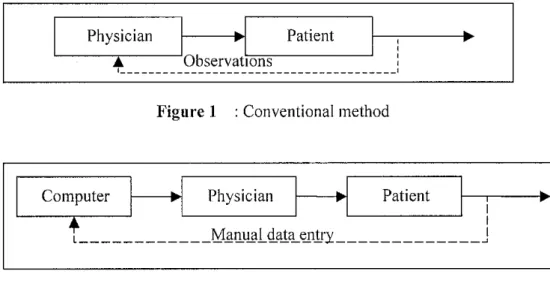
Usually, the rate of delivery is set by nurse or physician according to the past experience and observation, mathematical computation, or by trial and error as illustrate in Figure 1. The control action is taken manually either by adjusting the rate of infusion or by injecting the desired amount of the drug. Recently, the system was enhanced by using a computer to compute a recommended drug dosage and the infusion is done manually (Figure 2). However, the system was improved by the introduction of electronic drop counter that can determine the drip rate of IV delivery.
12
Physician Patient
• Observations
Figure 1 : Conventional method
Computer Physician Patient
I I
L Manual data entry I
Figure 2 : Computer assisted therapy
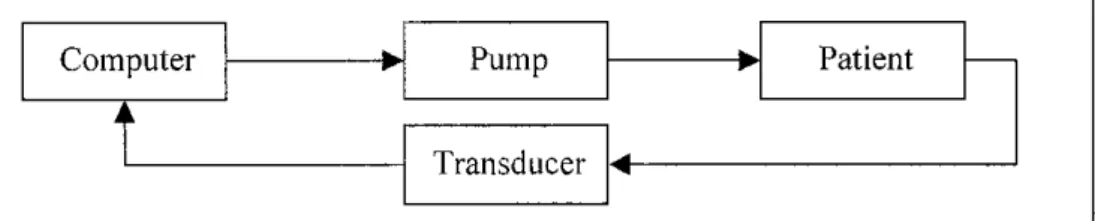
Basically, the infusions systems consist of two components, which is a mechanism that delivers the drug and a means of controlling the rate of delivery. Overall, the most current systems or devices operate in open loop system with continuous infusion and limited control of input. The delivery is said to be open loop if the rate of infusion is set a-prior and it is not automatically altered by the patient's response. Due to the limitation of open loop systems, the closed loop systems are among of developing systems designed to automate the control of physiological variable. In the closed loop, the desired delivery rate is computed and set automatically according to the condition of patient monitored by appropriate transducers or sensors (Figure 3).
For example in measuring temperature, a mercury-in-glass thermometer is the most popular method which are slow, difficult to read and susceptible to contamination.
Therefore, the electronic thermometers has become widely use for medical application due to its reliability and accuracy. The electronic thermometers might have various types of sensors for measuring. The accuracy must be addressed for patient safety concerns such as excessive delivery to avoid side effects occurs.
Computer Pump Patient
t
TransducerFigure 3 : Closed loop control
1.2 Problem Statement
1.2.1 Problem Identification
The current drug delivery apply the open loop system that requires frequent patient monitoring by the nurses and doctors to ensure an accurate flow rate with the current devices. Nurses and doctors need to gather the information during the monitoring to
determine the correct amount of volume and also the timing for medicine/water to bedelivered to the patient. Even with high tech pump systems, the patient still has to collect the data in order to adjust the pump rate and usually done manually by nurses or doctors. Therefore, the costs of medical care increase due to undivided attention from physician and nurse to manually control the infusion rate.
The calculations also are made based on the physician past experience, mathematical
computation, or by trial and error. For most of the cases, due to the human error might lead to wrong collected data such as mistake in decimal place dose. Thus, it can
affect the dose rate either to be excessive or insufficient. Besides that, the flow rate
using the traditional intravenous systems cannot be accurately controlled as it is counted in drops rather than in volumetrically. The rate also is difficult to adjust and
might change with time
1.2.2 Significant of theproject
The development of the water delivery system with response to changes in patient's temperature body will require less monitoring from nurses or doctors. This is due to
the device itself which can monitor and automatically react according to patient
body's behavior changes or needs. Besides that, through the development of this project, the human error in collecting the data can be reduced as the measurement and
calculation is done by the controller.
14
1.3 Objectives
The main purpose of the project is to introduce a delivery system that can supply medicine or water to patient with response to changes in the patient's body. The change described is in terms of body temperature of the patient. Another reason of this project implementation is to introduce the application of the closed loop system
in delivery system.
The second objectives is to study the relationship between the human body changes;
temperature with specific devices such as a sensor and to determine how the sensor can respond with human changes in controlling the medicine/water delivery system.
1.3.1 Feasibility of the Project within Scope and Time Frame
This project is categorized into two major phases. The first phase of the project
concentrates more on research on the related topic while the second phase is more on
the implementation of the project into a prototype. All the information about this
project can be obtained from books in the library and journals from the Internet. The
project is considered to be feasible within the time frame.
CHAPTER 2
LITERATURE REVIEW
In traditional drug delivery methods, drugs were delivered to the human body exclusively via oral and intravenous means [1]. Administration of intravenous infusion therapy has developed over the past 40 years from a comparatively simple procedure, relying on gravity, to the use of sophisticated multi-channel electronic pumps. These devices can calculate and administer multi-drug regimes and replace large volumes of fluid almost automatically [2].
Many hospital patients are likely to experience IV therapy, particularly following surgical procedures and during acute illness. It has been suggested that 63 per cent of surgical patients in Europe have an IV cannula inserted (Nystrom 1983) and at least 70 per cent of patients in acute care will receive IV therapy for at least part of their hospitalization (Feldstein 1986). A study conducted in a hospital in Wales indicated that approximately 16 per cent of all adult patients had IV therapy (Griffiths Jones 1990). This evidence clearly emphasizes the importance of IV maintenance
(Bostrom-Ezrati 1990) [2].
Basically, the administration of intravenous infusion therapy must involve with the control of flow rate as for the safety factors. IV running too fast 'Over infusion' is one of the greatest risks that healthcare professionals will encounter when administering IV medication. Circulatory overload and speed shock may occur if an infusion is
given too rapidly [2],16
The existence flow-control devices are used to regulate the infusion at the prescribed administration. Basically, there are two types of flow control devices; manual flow-
control devices and electronic infusion devices. The manual flow-control devices
include roller, screw, slide or regulator clamps and also volume control devices such as Buretrol [3].
The administration set contains a manual-flow device such as a slide clamp, a roller (regulator) clamp or a screw to regulate a prescribed infusion rate as showed in Figure 4. In other words, these devices are used to controls drip rate. The number of drops falling per minute is determined manually by nurses or doctors. The level of drip rate depends on the adjustment of the regulator clamp.
~m
10 drops/im
• Sude clamp
T . '
Regulating clamp
injection site
i , J.uRs ioc*. adapter
Vf Le-iVft? lODK C3s51Hb£S<
Figure 4 : Basic Administration Set [3]
Another type of manual-flow control is the Dial-a-Flo Regulation that uses a Dial-a- Flo regulator to regulate infusion of fluid at the desired rate. Like the previous method, the number of drip rate per minute is counted to ensure the accurate level of fluid being transferred. Gravitation is important to facilitate the drip rate. For the electronic infusion pumps such as controller infusion device is used to generate flow by gravity. The nurse sets the flow rate with the specific gravity with and the height of the bag to determine the maximum delivery pressure.
Electronic infusion devices are operated either by electricity or battery and are used to administer IV fluids and medications. There are two types of electronic infusion devices that are controllers and pumps. The controller infusion devices generate flow by gravity and are capable of maintaining a constant preset flow rate either by drop counting or volumetric delivery [3]. The flow rate and the specific gravity of the solution are set by physicians and the height of the bag determines the maximum delivery pressure.
Infusion pumps maintain the flow rate under positive pressure. Pump counter the effects of resistance in the delivery system and pressure fluctuations at the infusion site. Volumetric pumps use either pumping cassette or chamber to delivery a fixed volume over a specified period of time. Syringe infusion pumps rely on a syringe or cartridge to deliver the fluid at a specific set rate that is shown in Figure 5.
i . . „l. t:d'.i mm
T ,' |! hli!|l ,1.(1! jl |JilHIIIjHIIjMtf
-J mir
brM rave
per (9.4'nrs tiay
Figure 5 : Principle of Syringe Pump [4]
Most of the devices used are an open loop system and need frequent monitoring from nurses to collect the data in order to control the flow rate by adjusting the devices.
This might lead to the human error in tracking the patient's data. Besides that, the major difficulty with traditional intravenous infusion systems is the flow rate cannot be controlled accurately (Crass and Vance, 1985). The flow rate is counted in drops rather than measured volumetrically. The rate is difficult to adjust and will change with time [4].
Many incidents associated with IV devices - of which there has been a significant number - have been attributed to 'user error1 rather than 'machine failure' (Barker 1992, MDA 1995a). The fact that user error has been cited as the main problem has made it difficult to obtain reliable data regarding the causes of these incidents, perhaps because of the legal consequences which could result from the action or inaction of the staff involved [2].
2.1 Temperature Sensors
The stand-alone mercury-in-glass clinical thermometer was introduced from the early
20th century until recently [5]. It is accurate, stable enough, easy to use and
inexpensive. However, it has slow response, difficult to read and susceptible to contamination. Therefore, it has been replaced by the electronic thermometers, widely used due to its reliability, accuracy and rapid response. The electronic thermometers have various types of sensors for measuring used for medical application such as the thermocouples, electrical resistance thermometer, RTD andthermistor.
2.1.1 Thermocouple
A thermocouple is made of two dissimilar metals are joined together at either end, forming two junctions. The junction at the higher temperature is termed the hot or measuring junction while at the lower temperature (0°C), is the cold or reference junction (Figure 6). The thermocouple works by generating a small thermoelectric potential (emf) signal proportional to the temperature difference between the junctions of two metals. The thermocouple-based systems are simpler and are widely
available.
However, in designing them into systems is complicated by the need for special extension wires and reference junction compensation. They are often difficult and time-consuming to set up. The systems also demand users who are experienced and knowledgeable with both thermocouple technology (and its eccentricities),
temperature calibration methods and procedures. The thermocouples are normally used for measurements of surface skin temperature but generally measure relative temperature.
Measure junction
Cold junction
--« -t V Output
Figure 6 : Bridge type reference junction compensator [4]
2.1.2 Resistance Thermometer (RTDs)
Resistance thermometers or known as resistance temperature devices (RTDs), rely on the principle that the resistance of a metal varies with temperature. The metal normally used is either platinum or nickel, depends upon the linearity and sensitivity.
Thermometers are constructed from a coil of these metals (Figure 7). Resistance temperature detector probes tend to be larger and to require more peripheral equipment [6]. Resistance thermometer is used for rectal and body temperature while small thermistor probes is suitable for oesophageal, rectal and intravenous
measurements.
Compensating
leads
Figure 7 : Circuit arrangement of a metal resistance thermometer [4]
20
2.1.3 Thermistors
A thermistor is a resistive device made up of metal oxides that are formed into a bead and encapsulated in epoxy or glass. It is built by a high negative temperature coefficient (NTC) or positive temperature coefficient (PTC). NTC device decrease the resistance with increasing temperature and vice versa for the PTC device, causing a large voltage drop. NTC chip thermistor is one ofthe temperature sensors with high sensitivity response to temperature. The simplest circuit employing thermistors for temperature measurement is shown in Figure 8. Commercial thermistors are
available with 25°C resistance oflOOfi, 300^, lOkQ until 1MH.
Figure 8 : Elementary Voltage Divider with Thermistor [7]
Typically, the thermistor has various packages types, from a normal size until the
smallest size. The better choice of thermistor types is based on the application and the
properties required from the sensor. However, all choices involve trade-offs.
Basically, there are two common types of thermistor that are bead thermistors and
disk thermistors.
In terms of size, the bead thermistors are made much smaller that discs. Besides, the bead thermistors are more stable result from the customary glass encapsulation.
However, the stability of any thermistor depends upon the maximum temperature to which the sensor is exposed. Recently, the disks thermistors have been shown to
approach the stability of the best beads with the advantage of interchangeability,
which beads do not [7]. Reported stability for glass-coated disks is shown in Table 1.
Table 1 : Reported Stability for glass-coated disks for continuous operating temperature [7]
OP TEMP 1 MONTH 10 MONTH 100 MONTH
25°C <0.01°C <0.01C <0.01°C
70°C <0.01°C <0.01C <0.01°C
100°C 0.01°C 0.02C 0.01°C
150°C 0.03°C 0.05C 0.08°C
200°C 0.08°C 0.22C 0.60°C
The comparisons between these sensors are showed in Table 2 below. These sensors have their own advantages and disadvantages. The perfect choice for the temperature sensor types is based on the application, properties required from the sensor and also
involve with trade-off.
Table 2 : Comparison of temperature sensors [17]
RTD Thermocouple Thermistor
Temperature
range -260to850°C -270 to 1800°C -80tol50°C
(typical)
Sensor Cost Moderate Low Low
System Cost Moderate High Moderate
Stability Best Low Moderate
Sensitivity Moderate Low Best
Linearity Best Moderate Poor
Specify for:
General purpose sensing
Highest accuracy Temperature averaging
Highest temperatures
Best sensitivity Narrow ranges(e.g.
medical) Point sensing
22
2.2 Applications
The most common application of the thermistor is used in digital thermometer. It can be easily accomplished by interfacing a Wheatstone bridge, thermistor network and a digital voltmeter integrated circuit as illustrated in Figure 9. The IC consists of A/D converter and built-in LCD driver providing resolution 0.1°C. It can be interfaced with additional circuitry to provide a temperature control and digital display.
a s
MX.
^ ] T IX39 as 1 2£i 28 a*
-.ih-.tj~.-S>
Figure 9 : Digital Thermometer [15]
CHAPTER 3 METHODOLOGY
3.1 Project Methodology
The first phase of this project involves a lot of researches regarding the existence drug delivery devices. The purpose is to understand the operation of these devices for drug delivery and problems related. Hence, the improvement of the system can be made based on the information of the existence devices. The second stage is to develop a details mechanism of the drug delivery system with diagram to illustrate the mechanism of the system effectively. The final stage is to identify the components or gadgets that will be used to construct the sensor, monitoring device, delivery device and the also controlling device. Figure 10 below describes the summarization of the whole project methodology.
Researches
- existence drug delivery devices and problems occur
1
Study and research
-physiology of fluid, sensors and circuit
I
Development
details mechanism for drug delivery system (flow diagram)
I
Design - circuit for sensor
I
Identify
eadeets and comnonents for the several circuits
Figure 10 : Project methodology
24
3.1.1 Methodology Medicine/WaterDelivery System
The project is focused more on the temperature sensors with the microcontroller system. The first step is to decide the type of temperature sensor that is suitable to use for the project as well as for medical application. Through some research from the Internet and books, thermistor provides the most suitable characteristic for patient's body temperature sensor.
Then, suitable circuit of the sensor is determined such as the Wheatstone bridge circuit. At this stage, all the components involve must be decided including the types of controller. This circuit will simulate using the Electronic Workbench (EWB) or the PSpice software to ensure the functionality of the circuit as well to get the exact result of the circuit. The sensor is calibrated with the bridge circuit to prove the linearity of this sensor circuit and to obtain the output voltage value correspond to the
temperature.
Then, the sensor circuit (bridge circuit) is combined with the microcontroller to control the operation of the circuit. This step will involve some C programming of the microcontroller to control the whole system. Again, the process of simulation is done
to prove the whole circuit is well function before testing it on circuit board.
Study Build circuit Simulation
-temperature sensor
w
-Wheatstone Bridge -EWB
Simulation complete circuit
~4 Circuit + Microcontroller
-PIC programming 4 1
Figure 11 : Temperature sensor with controller system flow diagram
3.2 Tools
The main component, thermistor sensor that is needed for the project is not provided in the Lab and it is difficult to obtain. The components that are available in the Laboratory are PIC16F877, resistors, operational amplifier, LCD and the motor.
Below (Table 3) is the list of the components and software that are used for this
project.Table 3 : Lists of Components and Software
Component Thermistor
Resistors PIC16F877 LCD Board
Voltage Regulator 7508
Oscillator 4MHz
Software Electronic Workbench (EWB)
PSpice
PICC Compiler (CSS)
Hardware WRAP-13 board
26
4.1 Findings
CHAPTER 4 DISCUSSION
4.1.1 Thermistors Sensor
Thermistor sensor is selected due to the low cost and by using this sensor it will provide moderate cost for the whole system. For medical applications, thermistor are frequently taped to a patient's skin and used to control sensor for the temperature regulating system. Thermistors are electrically conductive elements that are designed to change electrical resistance in a predictable manner with changes in applied temperature. The quality of performance varies widely, in terms of interchangeability, stability, temperature range and others characteristics.
The NTC thermistor can be categorized into two major groups depending upon the method by which electrodes are attached to the ceramic body. The first group consists of bead types that include various types of glass beads and bare beads. The second group is thermistor that has metallized surface contacts such as disks and chips. The most suitable thermistor for medical application is the glass beads which is the most stable with higher accuracy and faster response compared to the second group.
Besides, thermistor or the sensor must have higher sensitivity for at least one decimal place which can be obtained from the glass bead.
Usually, a normal range for body temperature is always remains in a range 35 to 40DC. While for skin temperature, it may vary much more widely when the skin is cooled or warmed externally. Therefore, a thermometer for skin measurement must have wider range for example 0 to 50°C. A temperature resolution of O.TC is required in body temperature measurement and absolute accuracy of O.TC is acceptable for most medical purpose. For medical requirement, thermistor has the accuracy of +0.1°C and 4% change in resistance per degree centigrade. It is also has wider tolerance values range from +0.05°C to +0.2°C with high sensitivity of temperature changes.
However, the thermistor sensor obtained for this project does not meet the entire medical requirement. This NTC thermistor (Glass Bead) is a GM type that has resistance value of 4.7kH under reference temperature, 25°C. The lowest temperature of the thermistor is 25°C and the highest temperature is up to 125°C. Besides that, the resistance tolerances are quite large for medical application which is +20%.
Therefore, it is not suitable and practical for medical application. The thermistor datasheet is attached together in the Appendix B.
Table 4 : Thermistor Specification
Characteristic Description
Type Glass Bead NTC thermistor
Temperature range 25°Ctol25°C
Resistance 4.7kQat25°C
Tolerance + 20%
Voltage Supply lVto6V
28
Most of the glass bead thermistor sensors provided is for the industrial consumer application with too low and too high operating temperature. These thermistors are manufactured for general temperature measurement and control purpose such as fluid level detection and flow measurement and control. Besides that, most of the sensors also are made from metal and alloy such as aluminums which is not suited for medical especially for skin temperature measurement. A table of resistance and its temperature can be referred to the graph nominal resistance versus temperature that is attached in the thermistor datasheet (Appendix B).
4.1.2 Wheatstone Bridge Circuit
The basic circuit applied for the sensor measurement is the Wheatstone bridge circuit where the sensor is connected in a voltage divider network (Figure 12). The thermistor sensor is placed with another three resistors. The circuit produces a voltage output that varies linearly with temperature as the thermistor is a nonlinear device.
The value of thermistor resistance is usually depends on the environment temperature.
However, for this circuit, the resistance of the thermistor is A.lkQ, under the reference temperature which is 25°C. The output voltage for the circuit is the difference between the voltage drop across Rj and i?2.
The voltage output of the voltage dividers can be very small (close to zero) if Rj and R2 are both small compared to the other resistors. While the voltage output of the voltage dividers can be very close to the supply voltage if Rj and R2 are both large compared to the other resistors. The value of the R3 must be equal with the thermistor value,7\ while the Rj must equal with the R2 in order to obtain a bridge output of zero volts. When the Ri and R2 values are larger, the voltage output is increase.
R.R2-TR3-0
Figure 12 : Bride Circuit Simulation using PSpice (thermistor is replaced by normal resistor, T)
4.1.3 Calibration of Thermistor Sensor
According to the thermistor data sheet, the voltage supply can varies between IV up to 6V. However, this circuit works fine with supplier of 5V. The resistors used for the circuit is Rj= R2 =10kQ and T=R3= 4.7kQ. In the circuit, the NTC thermistor is utilized as the active legs. As the temperature increases, the voltage output also will
be increased.
This circuit is designed to produce 191mV at 30°C and 656mV at 45°C with the
application of 4.7k ohm thermistor. For this project, the temperature ranges that will
be considered are from 32°C to 40°C, suitable range for skin thermometer. The output from the bridge circuit is listed in the Table 5 which is in a milivolts.Table 5 : Output voltage (V0Ut) related to temperature
Resistance* Temp Simulation Experiment Graph,
kO (°C) (mV) (mV) (mV)
3.9 30 196 191.5 191.7
3.4 35 330 361.6 345
2.8 40 505 512.8 510
2.2 45 697 656.7 670
*Refer to the nominal resistance v temperature characteristic given in datasheet
30
The output values obtained are plotted in the Microsoft Excel to attain the linearity of the output voltage (Figure 13). The purpose of this plotted graph is to figure out the Vout at certain temperature. The Voui must be determined correctly for microcontroller input for other controlling purpose. The graphs plotted showed that thermistor circuit is linear to the output voltage. As the temperature increase, Vou( also increases.
However, the output voltages at certain temperature between plotted graphs and measured from circuit are slightly different.
100
Temperature vs Voltage Output
200 300 400
Vout(mV)
500 600
Figure 13 : Graph temperature versus voltage output
700
4.2 Discussion
Basically, this delivery system applies the closed loop systems where the patient's response is used to automatically adjust the infusion rate. The advantages of the closed loop are to improve patient care by delivering the right amount of agent for maximum effectiveness. The effectiveness is something that can be measured such as the body temperature. The second reason for using automated closed loop control is to reduce cost of medical care as the traditional system needs the physician attention and to manually control the infusion rate.
In fully automated system, the transducer or the sensor senses the control variable while the controller determines the infusion rate based on the discrepancy between the actual and desired variables and automatically computed infusion rate delivered by a pump. As a result, the system operates without human intervention until the delivery is completed or until malfunction of the system is detected.
The project is done for delivery system that has the feedback loop between the patients and the sensor. Basically the whole system is controlled by a microcontroller to control the mechanism of the pump according to the human body's temperature changes. The transducer or thermistor sensor is used to detect or to measure the changes of the patient's body temperature is connected by holding or wearing on wrist or attached to finger tips.
Thermistors are passive semiconductors which produce resistance values depend on temperature. The characteristics of this chip fulfill the requirement as the sensor device to detect the human physiology temperature. This sensor provides a narrow range of temperature which is between -80 to 150°C compared to other sensors.
The temperature of the human body will affect the thermistor and increase its temperature. The thermistor decrease in resistance as its temperature increase. By applying the Wheatstone bridge circuit, it will produce the equivalent output voltage according to the degree of temperature. The voltage produce is considered as the
32
input for the microcontroller. The microcontroller is used to monitor the rate of medicine/water delivery by controlling the movement of the pump. The illustration of
this closed loop delivery system is showed in Figure 14.Temperature Sensor
-thermistor sensor
Microcontroller PIC16F877
Monitor devices -LCD
Pump system -syringe pump
Patient
Figure 14 : Illustration of the Medicine/Water Delivery System
However, due to time constraint and limitation of the component, student only
completed for the monitoring part which consist of microcontroller, LCD together
with sensor circuit. For the pump system, the student managed to do the research partwhich will be discussed in the recommendation section.
4.2.1 Microcontroller System
In order to have a circuit that can monitor the temperature and control the delivery
system, the Wheatstone bridge circuit is enhanced by adding it to the microcontroller
system. Basically, the microcontroller will receive the input from the Wheatstone
bridge circuit and the outputs are used to control the mechanism of the pump system
and to display the current temperature value on the LCD.The Wheatstone circuit will send the data or information in analogue to the controller
which may involve some the calculation process. Then, this signal is sent to the pump system to control the mechanism that is operating in analogue system. The digital output of the microcontroller is connected to the LCD segments to display the
temperature value.The PICF877 that is chosen for this project has five ports of I/O; A, B, C, D and E.
The pin description of this PIC is given in Table 6. This chip provides large data memory that is 368 bytes and has a large space for programming. The features and
the information about PIC16F877 microcontroller is attached in Appendix C.Table 6 : Pin description of PIC16F877
Pin Description >
1 Reset inputand Vpp programming voltage of a microcontroller
2-7 PORT A pins
8-10 PORT B pins
11,32 Positive power supply 12,31 Ground of power supply
13-14 Pin assigned for oscillator 15-18,23-26 PORT C pins
19-22,27-30 PORT D pins
33-40 PORT B pins
This PIC16F877 provide built in successive-approximation A/D converter with 10 bit
multi-channel where the conversation time faster than digital-ramp ADC. There will be 1023 possible steps for this converter. This A/D module has high and low voltage reference input in the software selectable to some combination of Vdd, Vss, RA2 orRA3.
34
The A/D converter is assumed to have full scale (F.S) output of 5V. Therefore, the step size is 5mV.
Step size- F.S = 5V_-5mV 210-1 1023
Resolution of A/D converter is the smallest unit of measure. The resolution is always
equal to the weight of the LSB and also referred to as step size. The resolution
percentage is 0.1%.Step size x 100% -0.1%
F.S
4.2.2 Monitoring Device
The monitoring device is used to display the values or displays graph of the parameter such as human body's temperature. Liquid crystal displays (LCD) are preferred devices for display as they require very low current to operate with large screen size.
It has 14-pin access with eight data lines, three control lines and three power lines.
Pin 4, Register Select bit is used to select whether data or an instruction is being transferred between the controller and the LCD. If the bit is high, character data can be transferred to and from the module. When the line is low, data bytes transferred to the display and treated as commands.
For pin 5, this line is set to low in order to write commands and set to high to read status information from its register. Pin 6 is the Enable line, is used to initiate the actual transfer of commands between the module and the data lines. Pin 7-14 are the
eight data bus lines. Data can be transferred to or from the display either by a single
8-bit byte or two 4-bit "nibbles". Only the upper four data lines are used for the lattercase. The pin configuration for the LCD is given in Table 7.The LCD circuit is shown in Figure 15.
Table 7 : Pin Configuration for LCD
PIN Description
1 Ground
2 VCC
3 Contrast Voltage
4 "R/S" Instruction/Register Select
5 "R/W" Read/Write LCD register
6 "E" Enable 7-14 Data I/O Pins
VREG
T R3
/ Y _ _ _ _ / \
t
PIC16F877
R1 R2
Figure 15 : LCD Circuit
36
CHAPTER 5
CONCLUSION AND RECOMMENDATION
5.1 Relevancy to the Objectives
The main objectives in producing a delivery system that can supply medicine or water
to patient with response to changes in their body have not been achieved yet. At this
moment, the second objective regarding the relationship between the bodytemperature changes temperature with a sensor has been accomplished. Through
some research, the thermistor is chosen as temperature sensor due to the low cost andthe acceptable characteristic for medical application. However, the components itself
is hard to find either from the lab or the electronic shops. The thermistor that is available is the PTC type, which is different in application and requirement of theproject. The overall idea of the whole system has strongly established but the
components are hard to obtain.In overall, this project involves two major phases. The first phase of the project
concentrates more on research on the related topic such as selection of temperature sensor as well as designing the whole system which has been completed. The secondphase is focused more on the implementation of the project into a prototype.
However, due to time constraint and limitation of the components, the second phase of the project is not fully completed. The main component, thermistor sensor is obtained in the middle of the semester. The student managed to complete this project until the LCD part. Therefore, the result of this project is only for the monitoring part that is used to monitor skin temperature and display the value on the LCD.
In order for this project to be possible, the knowledge of programming in both C and assembly language is crucial as to program the microcontroller and to control the overall operation of the circuit. However, the knowledge in the programming can be
enhanced by reading materials and tutorials available on the microcontroller websites.
5.2 Suggested Future Work for Expansion and Continuation
5.2.1 Thermistor Sensor
The temperature sensor that is used for this project is not recommended and not practical for medical application. The sensor does not meet the medical requirement
in terms of tolerance and accuracy. Therefore, for this project to be more practical for real medical application, the thermistor sensor that is used must meet the entirerequirement and specification needed for the patient safety. The accuracy and higher
resolution is the most major consideration in selecting the right sensor.5.2.2 Motor System
As mentioned earlier, the project only completed until the LCD part. Therefore, for
the future work suggestion, this project should be enhanced with motor circuitry in order to produce a complete closed loop delivery system. A stepper motor is suitable for the project application with rating voltage around 12 Volts. Basically, a stepper
motor moves one step at a time. If the stepper motor is command to move some specific number of steps, it rotates incrementally that many number of steps and stops which is suitable to control the movement of the pump. Usually, the motor is connected to the worm gear which is used to control the pump movement. The infusion may be continuous or pulsatile. Besides that, several important factors are crucial in order to produce better performance such as the accuracy, speed, torque,and also execution time
5.2.3 Delivery and Monitoring Systems
The devices that are suitable to use for the medicine/water delivering is the syringe pump that has a worm gear mechanism and a holder for the syringe. A precision step motor will turn the worm gear and moving a push plate against the back of the
syringe (Figure 16). The device is mainly for the applications that require the delivery of volumes limited by the syringe size. Control is achieved by varying the stroke length or the stroke rate. However, the system also can be implemented to other delivery devices instead of using the syringe pump for example controlling the
valve opening for the administration of intravenous infusion therapy set.f-
MOTOR WO«M
.J.X
PUSH H.ATE
LSNCAft POieNTIOMETFR
\
SYSMJE
U
OLTC^lOW
FIXED M'XMT
Figure 16 : Application of Syringe Pump and Motor
For the monitoring systems, other feature can be added by monitoring from the computer through serial communication port.
5.2.4 Fabrication on PCB
The circuitry can be enhanced by proper fabrication of the circuit and wiring system on the circuit board. The circuit can be improved by using PCB as to make the circuit more systematic. The trouble shooting problem will be easier if the PCB were utilized for this project.
REFERENCES
[1] Alireza Khademhosseini, Controlled-release Microchip Drug Delivery Systems: Past, Present and Future (2000)
[2] Wilkinson R, Nurses' concerns about IV therapy and devices: Nurses' concerns about IV therapy and devices. Nursing Standard. 10 (1996) 35-37.
[3] S. C. Delaune, P. K. Ladner, Fundamentals ofNursing: Standard& Practice,
2002.
[4] RS Khandpur, "Handbook ofBiomedical Instrumentation", 2n Edition,
Tata McGraw-Hill.
[5] J. Hesse, J. W. Gardner and W. Gopel: Sensors in Medicine and Health Care, Volume 3, WILEY-VCH, 2004
[6] R. J. Moffat, Instrumentation and Control: Fundamental and Application, Temperature and Flow Transducer, WILEY-INTERSCIENCE, 1990.
[7] Henry E. Sostmann and Philip D. Metz, Fundamentals of Thermometry Part VI: Thermistor Thermometers, http://www.its-90.com/fp8-sig.pdf
[8] H. W. Trolander, Thermistor Development: At the Yellow Springs instrument Co., Inc, Volume 8, NO. 2,1997
[9] Daan J A Crommelin and Robert D Sindelar: PharmaceuticalBiotechnology,
2nd edition, Taylor & Francis, 2002.
[10] T. Togawa, Sensors in Medicine and Health Care: Home Health Care and Telecare, Volume 3, WILEY-VCH, 2004.
[11] Vadim Gerasimov and Walter Bender, Hand-held Doctor for Children,1999.
40
[13] J. J. Carr: Electronic Circuit Guidebook: Sensors, Volume 1, PROMPT Publications, 1997.
[14] Tatsuo Togawa, Toshiyo Tamura: Biomedical Transducers & Instruments, P.Ake Oberg, CRC Press
[15] www.veriteq.com/thermistor/index.htm [16] www.AlphaSensors.com
[17] www.chipdocs.com/pndecoder/number/710.html [18] www.microdaq.com
[19] www.farnell.com
APPENDICES
APPENDIX A PROJECT GANTT CHART
APPENDIX B NTC THERMISTOR DATASHEET
APPENDIX C PIC16F877 DATASHEET
42
APPENDIX A
PROJECT GANTT CHART
oannv^nau.nisioeniesieivreuiutny^uuj-iviaywjv) NoDescriptionW1W2W3W4W5W8W7W8W9W10W11W12W13W14W15 1BriefingonFYPBackground 2Topicassignedtostudents 3Researchexistance drugdeliverysystem/devices/problems 4Preliminaryreport 5Research/Study Temperaturesensors 6Developmentdeliverysystem/mechanism 7ProgressReport 8Research/designcircuitfordevice/sensor 9Identifycomponents 10InterimReport 11Oralpresentation
Chart:FirstSemester(July2005-Nov2005) W2W3W4W5W6W7W8W9W10W11W12W13W14W15W16 temperaturesensor Component
- Report1 Sensor Design Report1
_—=— Design Design Report
~—-
--—-~.
—- Report(softcopy) Report presentation Report
APPENDIX B
NTC THERMISTOR DATASHEET
44
BOWTHORPE THERMISTORS
Description
• Small size, fast response Typical applications include:
Q Temperature compensation of crystal oscillators Q Control of industrial boiler temperature
Q Monitor of machine lubricant flow
• Approved to CECC 43 000
• Resistance tolerances ±20%, ±10%, ± 5% at reference temperature.
• B value tolerance ±3%
a Time constant (cooling) = 5s
• Dissipation factor = 0.75mW/°C
• Typical resistance change after 10,000 hours at 25°C <1%
• Weight = 0.1g
• Pack quantity = 25
US
Jma>
Resistance Code Reference B Value ocat Reference rmax at
Group Resistance K 2S°C Temperature °C 25"C
O %/'C °C mW
GM221 220 25-85
-2.99 2655 331 330 2725 -3.07 471 470 2780 -3.13 681 680 2845 -3.20
LOW 102 1k 2910 -3.27 25 126 75
152 1.5k 3010 -3.39 222 2.2k 3125 -3.52 332 3.3k 3240 -3.64 472 4.7k 3340 -3.76 682 6.8k 3445 -3.88
103 10k 25-85
-4.00 3555 153 15k 3670 -4.13 223 22k 3780 -4.25 333 33k 3895 -4.38
MEDIUM 473 47k 3940 -4.43 25 200 130
683 68k 3995 -4.49 104 100k 4045 -4.55 154 150k 4100 -4.61 224 220k 4145 -4.66 334 330k 4200 -4.72
HIGH 474
684 25k 35k
10O-20C -4.86
-4.93 100 300 205
4320 4-'"M 105 50k 4« JO -5.04
Derating
AMBIENT TEMPERATURE
O NTC Thermistors
INDUSTRIAL/CONSUMER
PROFESSIONAL
TYPE QM
5.0
1 (•
max , . .
• ,
<h
25,4
cunila 0.350
*
Actual Size
Highly sensitive bead in solid glass pellet Temperature Measurement &Control
Fluid Level Detection Flow Measurement & Control
Coding Example
GM 47
GM TYPE
BASE RESISTANCE FACTOR AT 25°C
RESISTANCE MULTIPLIER 1 = 10' 2 = 10' 3= 10' 4 = 10' 5 = 10'
RESISTANCE TOLERANCE AT REFERENCE TEMPERATURE W= ±20%
Y = ± 10%
Z = ± 5%
eg.GM473Y=47xl0'O
= 47Kn±10%AT25°C
TYPICAL VOLTAGE - CURRENT CHARACTERISTICS IN FREE AIR AT 25°C
LOW RESISTANCE TYPES
TYPICAL VOLTAGE- CURRENT CHARACTERISTICS IN FREE AIR AT 25°C
MEOIUM RESISTANCE TYPES
CURRENT <m*|
TYPICAL VOLTAGE - CURRENT CHARACTERISTICS IN FREE AIR AT25'C
HIGH RESISTANCE TYPES
CURRENT(mA)
NG:
•s are designed to be intrinsically safe components provided aerated within the rated voltages or currents and inside the
ded temperature range.
il care required for electronic components should be exer-
L :
hazards are involved in disposal. Incineration of thermis- recommended due to the emission ol toxic fumes from led devices or the shattering of glass and/or ceramic with azard from hot jagged material.
PHYSICAL FORM :
The wireends should not be bent nearer than 3mm to the glass body
of the thermistor
PRODUCT SAFETY NOTES :
Although these devices are glass encapsulated no insulation proper ties are implied.
Some of the thermistors in this range, when operated at or near maximum rated dissipation in a self-heat mode, may require applied voltages capable of causing dangerous electric shock.
flammable fluids :
These devices attain high surface temperatures when used as liquid sensors. This precludes their direct use in flammable fluids; please contact the Technical Sales Department for further information.
i figures and data quoted In this docu- ical and must be specifically confirmed 1 BOWTHORPE THERMISTORS be-
;ome applicable to any particular order The company reserves the right to lions or amendments to the detailed at its discretion. The publication of n this document does noi imply free-
>atent or other protective rights of 'hermistors or others.
THORPE COMPONENTS LTD.
May 1989
D12-3
BOWTHORPE THERMISTORS CROWN INDUSTRIAL ESTATE PRIORSWOOD ROAD
TAUNTON
SOMERSET TA2 8QY
TELEPHONE 0823 335200 TELEX 46748
FAX 0823 332637
GM474
NOMINAL RESISTANCE v TEMPERATURE CHARACTERISTICS
APPENDIX C
PIC16F877 DATASHEET
45
M i c r o c h i p
© PIC16F87X
28/40-pin 8-Bit CMOS FLASH Microcontrollers
Devices Included In this Data Sheet:
PIC16F873 • PIC16F876
P1C16F874 • PIC16F877
Microcontroller Core Features:
High-performanceRISC CPU
Only 35 single word instructions to learn All single cycle instructions except for program branches which are two cycle
Operating speed: DC - 20 MHz clock input DC - 200 ns instruction cycle Up to 8K x 14 words of FLASH Program Memory, Up to 368 x 8 bytes of Data Memory (RAM) Up to 256 x 8 bytes of EEPROM data memory Pinout compatible to the PIC16C73B/74B/76/77 Interrupt capability (up to 14 sources)
Eight level deep hardware stack
Direct, indirect and relative addressing modes Power-on Reset (POR)
Power-up Timer (PWRT) and Oscillator Start-up Timer (OST)
Watchdog Timer (WDT) with its own on-chip RC oscillator for reliable operation
Programmable code-protection Power saving SLEEP mode Selectable oscillator options
Low-power, high-speed CMOS FLASH/EEPROM technology
Fully static design
In-Circuit Serial Programming™ (ICSP) via two pins
Single 5V In-Circuit Serial Programming capability In-CircuitDebugging via two pins
Processor read/write access to program memory Wide operating voltage range: 2.0V to 5.5V High Sink/Source Current: 25 mA
Commercial and Industrial temperature ranges Low-power consumption:
- < 2 mA typical @ 5V, 4 MHz - 20 uA typical @3V, 32 kHz - < 1 uA typical standby current
Pin Diagram
PDIP
HCLRWpp/THV- RAWAN0 RA1/AN1 RA2/AN2/VREF- RA3/AN3A/REF+
RA4/T0CKI RA5/AN4/SS RECURD/AN5 RE1/WR/AN6 RE2/C&AN7 VDO.
Vss.
OSC1/CLKIN OSC2/CLKOUT RCO/riOSC/TICKI RC1/T10SI/CCP2 RC2/CCP1 RC3/SCK/SCL RD0/PSP0 RD1/PSP1
c 1 VJ 403
L" 2 39 3
C 3 383
c 4 373
L" 5 36 1
c 6 35 2
c
8
34 1
r 8 33 3
c 9 oo
32 1
c 10 k 31 1
11 12
00
u. 30
29 1 3 c 13
O—
28 3
c 14 27 3
L 15 26 J
d 16 25 3
c 17 24 3
c 18 23 3
C 19 22 3
L 20 21 3
RB7/PG0 RB6/PGC RB5 RB4 RB3/PGM RB2 RB1 RB0/INT VOD Vss RD7/PSP7 RD6/PSP6 RD5/PSP5 RD4/PSP4 RC7/RWDT RC6/TWCK RC5/SDO RC4/SDI/SDA RD3/PSP3 RD2/PSP2
Peripheral Features:
• TimerO: 8-bit timer/counter with 8-bit prescaler
• Timerl: 16-bit timer/counter with prescaler, can be incremented during sleep via external crystal/clock
- Timer2:8-bit timer/counter with 8-bit period register, prescaler and postscaler
• Two Capture, Compare, PWM modules - Capture is 16-bit, max. resolution is 12.5 ns - Compare is 16-bit max. resolution is 200 ns
- PWM max. resolution is 10-bit
• 10-bit multi-channel Anatog-to-Digital converter
• Synchronous Serial Port (SSP) with SPI™ (Master Mode) and l2C™ (Master/Slave)
• Universal Synchronous Asynchronous Receiver Transmitter (USART/SCI) with 9-bit address detection
• Parallel Slave Port (PSP) 8-bits wide, with external RD, WR and CS controls (40/44-pin only)
• Brown-out detection circuitry for Brown-out Reset (BOR)
PIC16F87X
11.0 ANALOG-TO-DIGITAL
CONVERTER (A/D) MODULE The Analog-to-Digital (A/D) Converter module has five inputs for the 28-pin devices and eight for the other
devices.
Theanalog input chargesa sampleand hold capacitor.
The output of the sample and hold capacitor is the input intothe converter. The converter then generates a digital result of this analog level via successive approximation. TheA/D conversion oftheanalog input signal results in a corresponding 10-bit digital number.
The A/D module has high and low voltage reference input that is software selectable to some combination
of Vdd, Vss, RA2 or RA3.
The A/Dconverter has a unique feature of being able to operate while the device is inSLEEP mode. To operate in sleep,the A/D clock mustbe derived from the A/D's
internal RC oscillator.
The A/D module has four registers. These registers
are:
• A/D Result High Register (ADRESH)
• A/D Result Low Register (ADRESL)
• A/DControl Register*) (ADCONO)
• A/DControl Registerl (ADCON1)
The ADCONO register, shown in Register 11-1, con trols the operation of the A/D module. The ADCON1 register, shown in Register 11-2, configures the func tionsof the portpins. The port pinscan be configured as analog inputs (RA3 can also be the vottage refer ence) or as digital I/O.
Additional information on using the A/D modulecan be found in the PICmicro™ Mid-Range MCU Family Ref erence Manual (DS33023).
REGISTER 11-1: ADCONO REGISTER (ADDRESS: 1Fh)
R/W-0 RAV-0 R/W-0 R/W-0 R/W-0 R/W-0 U-0 R/W-0
ADON |
ADCS1 bit7
bit 7-6:
bit 2:
bit 1:
bitO:
ADCSO CHS2 CHS1 CHSO GO/DORI
bitO
R ~ Readable bit W = Writable bit U = Unimplemented bit,
![Figure 4 : Basic Administration Set [3]](https://thumb-ap.123doks.com/thumbv2/azpdforg/11088789.0/16.829.303.555.460.743/figure-4-basic-administration-set-3.webp)
![Figure 5 : Principle of Syringe Pump [4]](https://thumb-ap.123doks.com/thumbv2/azpdforg/11088789.0/17.829.218.638.542.718/figure-5-principle-of-syringe-pump-4.webp)
![Figure 7 : Circuit arrangement of a metal resistance thermometer [4]](https://thumb-ap.123doks.com/thumbv2/azpdforg/11088789.0/19.829.198.594.769.1014/figure-7-circuit-arrangement-metal-resistance-thermometer-4.webp)
![Figure 6 : Bridge type reference junction compensator [4]](https://thumb-ap.123doks.com/thumbv2/azpdforg/11088789.0/19.829.175.628.184.378/figure-6-bridge-type-reference-junction-compensator-4.webp)
![Figure 8 : Elementary Voltage Divider with Thermistor [7]](https://thumb-ap.123doks.com/thumbv2/azpdforg/11088789.0/20.829.344.542.384.576/figure-8-elementary-voltage-divider-thermistor-7.webp)
![Table 2 : Comparison of temperature sensors [17]](https://thumb-ap.123doks.com/thumbv2/azpdforg/11088789.0/21.829.77.700.591.868/table-2-comparison-of-temperature-sensors-17.webp)
![Table 1 : Reported Stability for glass-coated disks for continuous operating temperature [7]](https://thumb-ap.123doks.com/thumbv2/azpdforg/11088789.0/21.829.98.700.156.337/table-reported-stability-glass-coated-continuous-operating-temperature.webp)
![Figure 9 : Digital Thermometer [15]](https://thumb-ap.123doks.com/thumbv2/azpdforg/11088789.0/22.829.222.580.313.516/figure-9-digital-thermometer-15.webp)
