A project thesis submitted to the Civil Engineering Program Universiti Teknologi PETRONAS in partial fulfillment of the requirement for the. I hereby certify that I am responsible for the work submitted in this project, that the original work is mine except as specified in the references and acknowledgments, and that the original work contained herein was not performed or performed by -specified sources and persons. . This project essentially aims to investigate the motion responses caused by the over-exaggerated installation vessel that will be conducted in the Caspian Sea, Turkmenistan.
The model test is developed to predict the movement responses of the installation barge, the load distribution between the barge and the undercarriage during installation and the tension of the mooring lines. The model test is exposed to regular and random waves with variations in draft value and wave directions to explore the barge's 6 degrees of freedom (slltge, heave, sway, pitch, roll and yaw). The total number of six experiments conducted consists of regular and random waves; wave height; 0.01 m and 0.0372 rn; and wave period; 0.99 sec for both waves.
Ntinerical analysis of the vessel responses is subjected to surge and surge motions based on vessel prototype conditions. 34; The ingredients of an achievement lie in the dedication, patience, determination, good cooperation and the very good combination of all of us.
INTRODUCTION
Background of Study
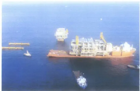
Integrated deck weight: Crane vessels are available with a lifting capacity of up to 14,000 tons, while float-overs are available up to 18,000 tons.
Problem Statement
The purpose of this project is to investigate the motion responses (the 6 degrees of freedom: lift, surge, pitch, roll, yaw and yaw) of the overdrive installation barge based on theoretical study using numerical analysis and model testing. The oceanographic data used for the numerical analysis and model test are based on Caspian Sea oceanographic data.
Scope of Study
- Shell's Malampaya Platform, Malaysia
- Float-over Stand-off
- Docking of Installation Vessel
- Pre-mating Position of the Installation Vessel
- Mating oflntegrated Deck to Jacket
- Post-Mating Position oflnstaDation Vessel
- Un-Docking of InstaDation Vessel
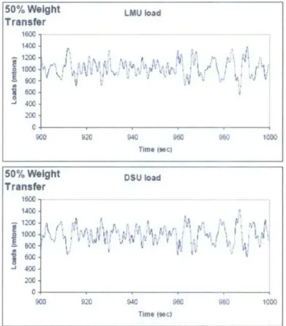
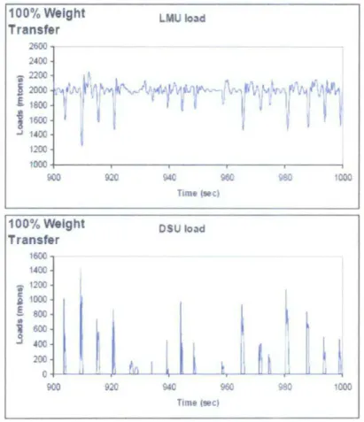
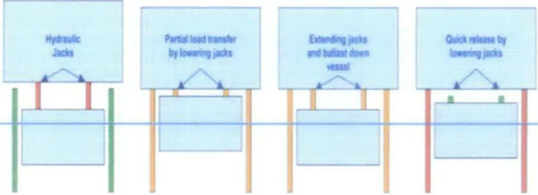
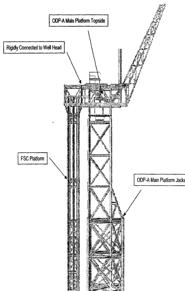
A typical float-over operation should basically experience the ballast and de-ballast stage of the ship, the alignment stage, the load transfer stage and the separation stage. PCTSB also engaged with Aker Offshore Oy to carry out a detailed design of the installation barge for the float installation of ODP·A Topside over the four·. The analysis tools developed produced reliable and repeatable results in the selection and design of components critical to the success of the switch.
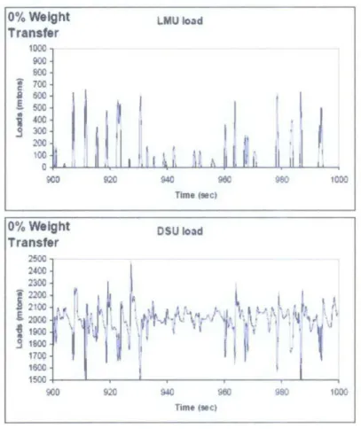
The upper side is connected to the barge using rigid connection simulation that is the stiffness of the DSUs. By locking these hydraulic jacks when the installation vessel is on top of the wave, a smooth initial load transfer from the vessel to the casing is achieved. After the completion of unloading, the integrated deck must be sea-secured on board the installation vessel before the sea voyage commences.
One aspect of the transport that is always crucial for a float-over transport is the stability of the vessel. The mooring spread for the vessel will depend on the field layout and the design environmental conditions for this phase of the operation. Control over the movement of the vessel in longitudinal and lateral directions, as well as control over the alignment of the vessel.
Limited lateral movement of the vessel in relation to the undercarriage to ensure adjustment of deck legs and jacket legs. In this phase, the installation of the integrated deck on the jacket will be carried out. The transfer of the deck weight can be achieved by a variety of methods, such as ballasting the installation vessel or active hydraulics in the deck supports.
As long as these shock loads occur, uncoupling the ship is not feasible. Therefore, the clearance between the module and the deck support must be increased by continuing to ballast the installation vessel. Limited lateral movement of the vessel relative to the jacket to ensure alignment of the integrated deck and supports on the vessel;
After the completion of the ballasting operations to increase the distance between the deck supports and the integral deck, the vessel can be detached from the undercarriage. Control over the movement of the vessel in longitudinal and transverse directions as well as control over the alignment of the vessel.
Studies of Float-over Installation
- Frequency Domain Analysis
- Hydrodynamic Added Mass and Damping Coefficients
- Froude-Krylov Force
X is the distance from the windward shore called fetch, or the distance at which the wind blows at a constant speed. If the barge is free to move in waves, its motion may be critically close to the resonance of the structure. Therefore, it is important to study the overall response of the barge due to the design wave spectrum.
In this case, the response amplitude operators are written that relate the dynamic motion of the barge to the wave forcing function on the vessel. Note that the motion of the bowl in the direction, x, is decoupled and can be modeled by a simple linearly damped spring-mass system. If m is the total mass of the van, K is its stiffness coefficient and Cis the damping coefficient, then its equation of motion is: [6].
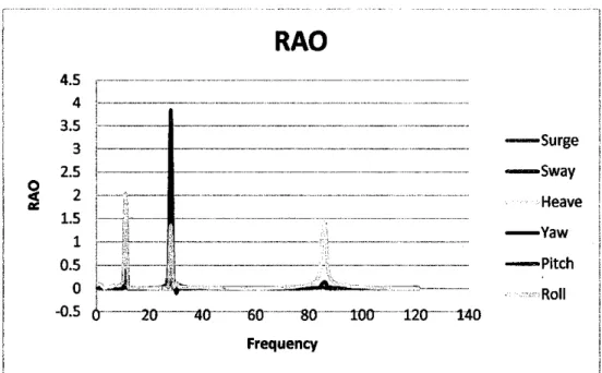
This relationship can be transformed to obtain the motion spectrum in terms of the wave spectrum and a RAO. The responses can be motion (displacement, speed and acceleration), loads (force and moment), and stress. The movements of a floating structure are influenced by the added mass effect in the water and the damping introduced by the movement of the structure in the water.
For small members of the structure these values are obtained from experiments, while when the size of the structure is large these quantities can be obtained analytically. The motions of a large floating structure are obtained with the help of the complete linear potential flow theory. It compares the Froude-Krylov force, the diffraction force on the structure at its equilibrium position, and the radiation force due to the movement of the structure about its equilibrium position.
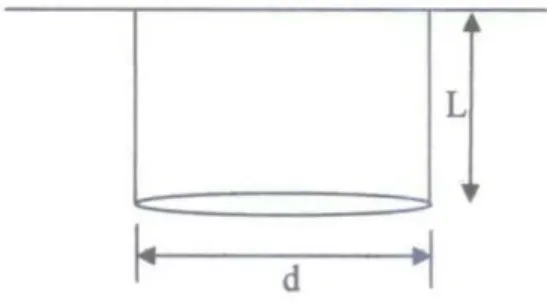
The last component gives the hydrodynamic coefficients of the structure in its six degrees of motion in terms of the added mass and damping coefficients. The Krylov force is the force introduced by the unsteady pressure field generated by undisturbed waves. The volume of the block is noted as V=h 1213• However, some adjustments must be made, as the barge is not quite a rectangular block and the dimensions also vary from bow to bow.
CHAPTER3
Numerical Analysis by using Microsoft Excel .1 Froude-Krylov Force
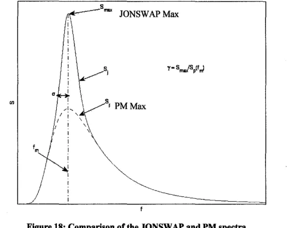
- JONSW AP Spectrum
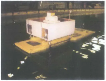
Model Fabrication
Experimental Programs
- Static Offset Test
GM is the distance between the ship's center of gravity and its metacenter. The test is performed by moving known weights on the deck and measuring the distance moved and heel or trim angle. The results of these tests are presented in Table 3 and Table 4 for pitch and roll respectively.
Displacement, initial end change Weight distance GM W(k:N) angle of angle of moved into angle offset. Based on the Bifiliar Pendulum method, the mass moment of inertia can be determined by suspending the subject from two ropes stretched from one side of the subject to the other. The mass moment of inertia of this ship varies between yaw, roll and pitch conditions.
Time is taken along the period from when the ship begins to rotate about the axis, until the ship remains static. The first phase of the physical modeling study involves determining the ship's dynamic response and RAOs. After the ship's moment of inertia has been determined, the wave test can be performed.
For the regular wave the test is performed in 2 minutes while for the random wave it is 25 minutes. Three optical tracking cameras are used to record the barge's 6-degree-of-freedom motion by detecting the reflection of the lamps. Load cells are attached to each anchor line to measure the voltage on each anchor line.
Four mooring lines are used and each of them is hooked to the edge of the barge; two at the fork, while the other two at the bow.
CHAPTER4 RESULT & DISCUSSION
RAO for Heave
RAOforSway
RAO for Surge
RAOfor Roll
RAOforYaw
Therefore, the RAO will be identical for all wave conditions with the same peak frequency. For rotation, the maximum RAO lies in the frequency range of l 0 Hz. b) The maximum RAO is reached when the barge has experienced deceleration while when it rises, the minimum RAO is reached. Based on a water current, single-wave headings, with a single condition for both regular and random waves, this project succeeds in achieving its objective.
The incomplete equipment available at the laboratory is one of the limited time factors as a lot of time is needed to search and manufacture the equipment. Lack of expertise to handle the laboratory equipment especially the wave generator also drained the precious time. In general, the float-over installation method has been and will be the important role in the oil and gas industry.
The method will be continuously improved to achieve perfection in offshore installations. The important factor in choosing float-over installation as the preferred installation method is that float-over operation requires only one asset for both transportation and installation. The number of assets exceeds the number of available crane vessels and the assets are easier to mobilize.
As a result, the cost of the overdrive installation is lower compared to an installation by crane vessel and makes it the attractive alternative for offshore installation. In the future, the model test can be completed and the goal achieved as the equipment for the model test is completely available. With more time available, all the variation of wave headings and draft can be performed to achieve the accurate results for the ODP-A Topside float-over installation.
So this project is a very good introduction for the student to understand the mechanism of float-over installation.