Experimental Studies on the Effect of the Particle Shape and Distributor Blade Overlap Angle on the Bed Pressure Drop in a
Swirling Fluidized Bed
by
Jeevaneswary AlP Marimuthu
Dissertation submitted in partial fulfillment of the requirement for the
Bachelor ofEngineering (Hons) (Mechanical Engineering)
MAY2011
Universiti Teknologi PETRONAS Bandar Seri Iskandar
31750 Tronoh Perak Dam! Ridzuan
CERTIFICATION OF APPROVAL
Experimental Studies on the Effect of the Particle Shape and Distributor Blade Overlap Angle on the Bed Pressure Drop in a Swirling Fluidized Bed
Approved by,
by
Jeevaneswary AfP Marimuthu
A project dissertation submitted to the Mechanical Engineering Programme
Universiti Teknologi PETRONAS in partial fulfillment of the requirement for the
BACHELOR OF ENGINEERING (Hons) (MECHANICAL ENGINEERING)
UNIVERSITI TEKNOLOGI PETRONAS TRONOH, PERAK
May 2011
I
CERTIFICATION OF ORIGINALITY
This is to certify that I am responsible for the work submitted in this project, that the original work is my own except as specified in the references and acknowledgement, and that the original work contained herein have not been undertaken or done by unspecified sources or persons.
JEEVANESWARY AlP MARIMUTHU
ABSTRACT
Swirling Fluidized Bed (SFB) is a newer variant of fluidized bed. Although it's been investigated by many researchers, a good understanding of its hydrodynamics and the effects of different design parameters on it is yet to be established. In fluidized bed processes, bed pressure drop is crucial as it determines the power required. The present work is an effort to investigate the effect of particle shape and distributor blade overlap angle on bed pressure drop in a SFB. In this study, bed particles of different shapes (cylindrical, spherical and oval) were used with different bed weights (500g, 750g and lOOOg). The experiments were conducted with various distributor blade overlap angles (9", 12", 15" and 18") at constant blade inclination of 1 0". The experimental set up used in this research is shown in Figure 12 and Figure 18. Batch experiments were carried out with increasing the bed weight from 500g to 1 OOOg in a step of 250g of bed particle for each shape and each distributor blade overlap angle. The results obtained were tabulated. Graphs were plotted to show the bed pressure drop variation with superficial velocity for each particle shape and distributor overlap angle. Figure 22 until Figure 39 show the results of this experiment. Result analysis confirmed that spherical particle has a higher bed pressure drop among the three shapes. Besides that, distributor blade overlap angle of 9" gives higher bed pressure drop as well. Hence, particle with spherical shape and blade overlap angle of9" influenced the bed pressure drop the most. In the meantime, oval shape particles have lowest minimum fluidization velocity as compared to cylindrical and spherical particle. As a conclusion, the research conducted proves the superiority of SFB over conventional bed.
111
ACKNOWLEDGEMENT
A house is not built from a single brick. It's made up of many bricks joint together.
Similarly, this research would not be completed successfully if there is no guidance or support from many people. Therefore, here, the author would like to express her utmost appreciation and gratefulness for those was the back bone for this research completion.
First of all, the author would like to thank her Final Year Project (FYP) Supervisor, Professor Dr. Vijay R.Raghavan for accepting her as his FYP student. Author would not be able to complete this research without his guidance and assistance throughout this research. His vast knowledge in Swirling Fluidized Bed (SFB) field and also his willingness to lend a helping hand were a great inspiration to author. He had always there for author to guide her. Hence, author truly appreciates his exceptional dedication.
Special thanks to UTP graduate assistant (GA), Mr.Vinod Kumar, for his generosity in helping and guiding author in setting up and conducting the experiment. Without Mr.Vinod's guide, author would not be able to complete this research. Besides that, author also conveys her thanks to Mr.Hazri, UTP Hydraulic Laboratory technician, for allowing her to use laboratory for her experiment.
Last but not least, author also would like to thank her family and also her friends for their continuous support in completing this research. As a conclusion, the author is grateful to all that helped her, guided her and supported her throughout this research and made it a successful research.
TABLE OF CONTENTS
CERTIFICATION OF APPROVAL.
CERTIFICATION OF ORIGINALITY .
ABSTRACT.
ACKNOWLEDGEMENT .
LIST OF FIGURES .
LIST OF TABLES .
ABBREVIATION AND NOMENCLATURES .
CHAPTER!:
CHAPTER2:
CHAPTER3:
INTRODUCTION . 1.1 Background of Project 1.2 Problem Statement
1.3 Objectives and Scope of Study
LITERATURE REVIEW 2.1 Fluidization
2.2 Swirling Fluidized Bed (SFB) 2.2 Distributor Pressure Drop.
2.3 Bed Pressure Drop
METHODOLOGY . 3.1 Experimental Set Up.
3.2 Procedures of the Experiment.
3.3 Project Planning (Gantt chart)
v
II
lll
IV
VII
IX
X
1 1 2 3
4 4 8 11 13
19 19 22 24
CHAPTER4:
CHAPTERS:
REFERENCES
APPENDICES
RESULTS AND DISCUSSIONS 4.1 Results
4.2 Discussion.
CONCLUSION AND RECOMMENDATION.
5.1 Conclusion
5.2 Recommendation .
26 26 33
37 37 38
39
41
List of Figures
Figure 1: Schematic diagram of fluidization process 5
Figure 2: Conventional Fluidized Bed Combustor Boiler 6 Figure 3: Schematic diagram and basic configuration of Swirling Fluidized 8
Bed
Figure 4: Annular spiral distributor 12
Figure 5: Experimentally obtained bed pressure drop, in mm of water 15 Figure 6: Bed pressure drop against superficial velocity for variable bed 16
loading
Figure 7: Bed pressure drop against superficial velocity for different blade 16 overlapping angle
Figure 8: Bed pressure drop against superficial velocity for different bed 16 weight
Figure 9: Bed pressure drop against superficial velocity for different number 17 of blades
Figure 10: Variation of bed pressure drop with superficial velocity for the 17 inclined-blade three-row, inclined-blade single-row and perforated
plate with inclined hole type distributor respectively
Figure 11: Rearrangement process 18
Figure 12: Experimental Test 20
Figure 13: Perspex Cylinder and plenum chamber which make up the bed 20
Figure 14: Shape of blade used in this experiment 20
Figure 15: Blade overlap angle 20
Figure 16: Annular Spiral 21
Figure 17: Digital Manometer 21
Figure 18: Overall Experimental Set up 21
Figure 19: Cylindrical, Oval and Spherical particle respectively 23
Figure 20: Gantt chart for FYP I 24
Figure 21: Gantt chart for FYP II 25
Figure 22: Variation of bed pressure drop with V superficial with blade overlap 26 angle of 9° for different shape of particle with bed weight of 500g
Figure 23: Variation of bed pressure drop with V superficial with blade overlap 27 angle of9° for different shape of particle with bed weight of750g
Vll
Figure 24: Variation of bed pressure drop with Vsuperficial with blade overlap 27 angle of9' for different shape of particle with bed weight of IOOOg
Figure 25: Variation of bed pressure drop with Vsuperficial with blade overlap 27 angle of 12' for different shape of particle with bed weight of500g
Figure 26: Variation of bed pressure drop with Vsuperficial with blade overlap 28 angle of 12' for different shape of particle with bed weight of 750g
Figure 27: Variation of bed pressure drop with Vsuperficial with blade overlap 28 angle of 12' for different shape of particle with bed weight of I OOOg Figure 28: Variation of bed pressure drop with Vsuperficial with blade overlap 28
angle of 12' for different shape of particle with bed weight of 500g
Figure 29: Variation of bed pressure drop with Vsuperficial with blade overlap 29 angle of 15' for different shape of particle with bed weight of 750g
Figure 30: Variation of bed pressure drop with Vsuperficial with blade overlap 29 angle of 15' for different shape of particle with bed weight of
Figure 31: Variation of bed pressure drop with V superficial with blade overlap 29 angle of 18' for different shape of particle with bed weight of 500g
Figure 32: Variation of bed pressure drop with V superficial with blade overlap 30 angle of 18' for different shape of particle with bed weight of 750g
Figure 33: Variation of bed pressure drop with Vsuperf1cial with blade overlap 30 angle of 18' for different shape of particle with bed weight of IOOOg Figure 34: Variation of bed pressure drop with Vsuperficial for cylindrical shape 30
particle for bed weight of750g with different distributor overlap angles
Figure 35: Variation ofbed pressure drop with Vsuperficial for spherical shape 31 particle for bed weight of750g with different distributor overlap
angles
Figure 36: Variation of bed pressure drop with Vsuperficial for Oval shape 31 particle for bed weight of750g with different distributor overlap
angles
Figure 37: Variation of bed pressure drop with Vsuperficial for different bed 31 weights with spherical shape particle and blade overlap angle of 9'
Figure 38: Variation of bed pressure drop with Vsuperficial for different bed 32 weights with cylindrical shape particle and blade overlap angle of 9'
Figure 39: Variation of bed pressure drop with Vsuperficial for different bed 32 weights with oval shape particle and blade overlap angle of 9°
List of Tables
Table 1: Advantages and disadvantages of fluidization
Table 2: Comparison between conventional fluidization bed and SFB
7 11
ABBREVIATION AND NOMENCLATURES
Ar
u
k
(!)
dp
PP Po
g J.lG L'.p (L'.p )b,s
Dp SFB PVC
Mean area (m2)
Archimedes number Velocity
Blade angle
Fractional void volume
Porosity at minimum fluidization
Fraction of the bed weight supported by fluidizing gas Angular velocity (rad s-1)
Particle diameter Particle density Gas density
Gravitational constant Gas viscosity
Pressure drop
Bed pressure drop in swirl mode Reynolds number
Minimum fluidization velocity Drag coefficient
Particle shape dependant Species dependant
Ratio of distributor pressure drop to bed pressure drop Height of bed
Mass of bed (kg) Mass-flow rate of fluid
Effective diameter of particles Swirling Fluidized Bed
Polyvinyl Chloride
1.1 Project Background
CHAPTERl INTRODUCTION
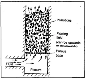
Fluidization is a process whereby a bed of solid particles is transformed into a state where it behaves like a fluid when a gas or liquid is passed through this bed of particles. When the gas or liquid flows through the gaps in between the solid particles, it will exert a drag force on the particles. As the flow increases, the drag force exerted on the particles is large enough to disturb the arrangement of the particles. Then, the upward or vertical motion velocity is raised progressively, which makes the drag force exerted on the particles sufficient to support the particles' entire weight. Hence, the solid particles are said to be fluidized and behave like a fluid. As a result, the particles said to be having many properties and characteristics of a liquid such as the ability to free-flow under gravity.
The advantages of fluidization which is solid-fluid contacting are rapid mixing of solids, high rates of heat transfer as well as mass transfer and finally the containment of well-mixed solid particles at a uniform temperature that resists sharp temperature fluctuations and allows exothermic reactions to be carried out in controlled temperature. Therefore, it is widely used in applications such as heat recovery, treatment of metal surfaces, heat exchangers, gasification, and combustion of solid fuels, waste treatment, endothermic and exothermic reactions.
Limitations in conventional fluidized bed have resulted in development of new beds such as circulating fluidized bed, centrifugal fluidized bed, vibro-fluidized bed, magneto-fluidized bed, tapered fluidized bed, spouted fluidized bed and swirling fluidized bed. Swirling Fluidized Bed (SFB) is still very new in fluidization field.
The gaseous medium in SFB enters at an angle through the inclined opening of the
distributor where the vertical component causes fluidization and the horizontal component caused swirling motion. These features distinguish SFB with conventional fluidized bed.
1.2 Problem Statement
In industrial processes, which involve gas-solid contact, bed pressure drop is crucial in determining the power required. The process can be either diffusion controlled or kinetically controlled. Diffusion controlled process normally dependent on the porosity of the bed material used. The best example of the diffusion controlled process would be the drying of wheat. Meanwhile, kinetically controlled process is dependent upon the velocity of the gas flow. Combustion process is one of the kinetically controlled processes. Besides that, pressure drop also occurs due to the rearrangement of particles during fluidization. Rearrangement of particles occurs when the particle being lifted and fluidized inside the bed. Therefore, experimental studies need to be done in order to indentifY the parameters that influence the bed pressure drop in SFB.
Hence, this project is carried out to study the effect of particle shape and distributor blade overlap angle on the bed pressure drop. Bed pressure drop is one of the hydrodynamic characteristics of Swirling Fluidized Bed (SFB). Therefore, experimental studies on the effect of the particle shape and distributor blade overlap angle will describe about the bed behavior which will affect the hydrodynamic behavior of SFB. Bed pressure drop also will have effect on the various reactions taken place inside the SFB. Thus, by analyzing the influence of the particle shape and distributor overlap angle on the bed pressure drop, one is able to control the kinetics of the different reaction occurring inside the SFB and also able to produce quality fluidization process.
There are numerous research are carried out in SFB field by many researchers from various countries all around the world. However, only few had conducted research on bed pressure drop. Moreover, this experiment is conducted with different particle shapes as well as different distributor blade overlap angles. Besides that, the author
studies the relation between these two parameters, particle shape and distributor blade overlap angle, with bed pressure drop. Once, the author has studied the effect of these two parameters, she is able to know and analyze the behavior of the bed.
Therefore, this project can be a good platform to study about the bed pressure drop.
In a nut shell, the results of this experiment not only will show superiority of SFB over conventional bed but also will establish a relation between the aspects discussed and the bed pressure drop.
1.3 Objectives and Scope of Study
1.3.1 Objectives
This project is regarding the Swirling Fluidized Bed (SFB ). The author will study about the fluidization process and the hydrodynamic behavior of the SFB particularly on the effect of the particle shape and distributor blade overlap angle on the bed pressure drop. Therefore, below are the objectives of this project:
a) to study the effect of the particle shape on the bed pressure drop
b) to study the effect of the distributor blade overlap angle on the bed pressure drop
c) to establish relation between particle shape and distributor blade overlap angle with bed pressure drop
1.3.2 Scope of Study
At the end of this research, the author able to have the followings:
a) Better understanding of hydrodynamics of SFB
b) A new classification for particles in SFB, like Gel dart classification m conventional bed
c) Effectiveness of the slugging regime in SFB
2.1 Fluidization
CHAPTER2
LITERATURE REVIEW
In various technological operations it often requires to bring a granular material into intimate contact with a fluid. The simplest way of doing it is trough fluidization process. Fluidization is the fundamental concept that used to develop different types of fluidization bed and currently used in industrial applications such as circulating fluidized bed, centrifugal fluidized bed, vibro-fluidized bed, magneto-fluidized bed, tapered fluidized bed, spouted fluidized bed, swirling fluidized bed and etc. Since the conventional fluidized bed have certain limitations, therefore it leads to the further development in fluidized bed and as a result these fluidized beds are developed. The common feature shared among these fluidization beds is the fundamental concept, which these beds are based on; although they are differ to each other in certain aspects.
Vanecek C.Sc. et al (1966) says on increasing rate of flow, the pressure drop across the bed will also be increasing until, at a certain rate of flow, the frictional drag on the particles will become equal to the effective weight of the bed and in this state the bed of particles attains properties similar to those of fluids; hence it is called a fluidized bed. He also mentioned that this condition and the velocity corresponding to it are termed incipient fluidization and incipient fluidizing velocity respectively.
Meanwhile, according to Kunii and Levenspiel (1990), at a point where all the particles suspended by the upward-flowing gas or liquid, the frictional force between particle and fluid just counterbalances the weight of the particles, the vertical component of the compressive force between adjacent particles is appears, and the pressure drop through any section of the bed about equals the weight of fluid and particles in that section, thus the bed is said to be fluidized. In other words, fluidization is a phenomenon of imparting the properties of a fluid to a bed of particles by passing a fluid through it at a velocity which brings the fixed bed to its
loosest possible state just before transformed it into a fluidized bed. (Gupta and Sathiamoorthy, 1999, pg 1 ).
Interstices
Flowing fluid
(can be upwards or downwards)
Porous base
Figure 1: Schematic diagram of fluidization
Minimum fluidization velocity, Umf, is important in fluidized bed. It is the velocity at which fluidization start to begin. According to K.S.Lim et a! (1995), minimum fluidization velocity is based on the balance of pressure drops required to support the weight minus buoyancy acting on the particles at the point of minimum fluidization.
Based on the Ergun' s equation, minimum fluidization velocity, Umf, is calculated using the equation below:
Where:
11p = (pp- PG) PP- Particle density PG-Gas density dp -Particle diameter J.lG-Gas viscosity
Remr = (PG dp Umr) I J.lG Ar = (PG 11p g dp3) I f.IG2
Umr-Minimum fluidization velocity
C1, C2 - Particle shape dependant and species dependant
Ar-Archimedes number Remr- Reynolds number
Besides the equation mentioned earlier, Umf, also can be found using Ergun's equation directly by substituting superficial fluid velocity with Umf and the pressure drop across the bed is equal to the effective weight per unit area of the particles at the point of incipient fluidization as per below:
~p = (pp-pg)(l - BM)gL
150~Umr (1-sM)
+
1.75 pg(Umr)2 _I _ _g(pp-pg)(Dp/ (sMi Dp (sMi
Rang r. Pattipati and C.Y. Wen (1981) said that the minimum fluidization velocity is affected by temperature. It decreases with increasing temperature for small particles.
They also mention that for small particles and at high temperature, the viscous forces are dominant. However, for larger particles, kinetic forces are dominant compared to viscous forces.
Particles inside the fluidized bed are called bed particles. A fixed bed is a layer of particles which rest on one another and do not move relative to one another or relative to the walls of the container as said by Vanecek C. Sc. et al ( 1966). On the other hand, moving bed is a layer of particles moving as a whole under the action of gravity. After reach fluidization state, the volume of the bed is somewhat larger than the volume of the fixed layer. Thus, the bed is said to be expanded. If we further increase the velocity of the fluid, the bed continues to expand and the height of the bed increases. However, the concentration of particles per unit volume of the bed decreases.
Figure 2: Conventional Fluidized Bed Combustor Boiler
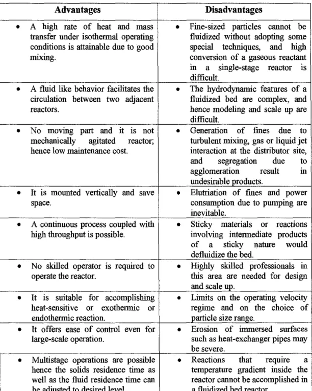
The advantages and disadvantages of fluidized bed are illustrated in the table below based on Gupta eta! (1999):
Table 1: Advantages and disadvantages of fluidization Advantages
• A high rate of heat and mass transfer under isothermal operating conditions is attainable due to good mixing.
• A fluid like behavior facilitates the circulation between two adjacent reactors.
• No moving part and it 1s not mechanically agitated reactor;
hence low maintenance cost.
• It is mounted vertically and save space.
• A continuous process coupled with high throughput is possible.
• No skilled operator is required to operate the reactor.
• It IS suitable for accomplishing heat-sensitive or exothermic or endothermic reaction.
• It offers ease of control even for large-scale operation.
• Multistage operations are possible hence the solids residence time as well as the fluid residence time can be adjusted to desired level.
Disadvantages
• Fine-sized particles caunot be fluidized without adopting some special techniques, and high conversion of a gaseous reactant in a single-stage reactor is difficult.
• The hydrodynamic features of a fluidized bed are complex, and hence modeling and scale up are difficult.
• Generation of fines due to turbulent mixing, gas or liquid jet interaction at the distributor site, and segregation due to agglomeration result m undesirable products.
• Elutriation of fmes and power consumption due to pumping are inevitable.
• Sticky materials or reactions involving intermediate products of a sticky nature wonld defluidize the bed.
• Highly skilled professionals m this area are needed for design and scale up.
• Limits on the operating velocity reglffie and on the choice of particle size range.
• Erosion of inlffiersed surfaces such as heat -exchanger pipes may be severe.
• Reactions that requrre a temperature gradient inside the reactor caunot be accomplished in a fluidized bed reactor.
2.2 Swirling Fluidized Bed (SFB)
Swirling Fluidized Bed (SFB) is the latest development and the new variant in fluidized bed. Although SFB still a new variant, but the concept of SFB is commercially available in industrial applications. However, the published information on SFB behavior is insufficient. Therefore, there are plenty of opportunities in this field to be explored in order to improve the SFB. However, from the past research on SFB, it is known that SFB is more energy efficient compared to other methods of fluidization since in SFB each particle get equal opportunity to fluidize. Besides that, SFB has following advantages compared to conventional fluidized bed. (Vinod et al, 2010).
a) Low distributor pressure drop
b) No bubbling, hence absence of slugging and channeling
c) High quality fluidization with better mixing due to the toroidal motion of particles
370" 370
- ---.. - f - - - 1
Wlndhnx
J
Alrlnlc< .,:110 I
i
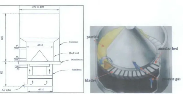
Figure 3: Schematic diagram and basic configuration of Swirling Fluidized Bed
Sreenivasan and Raghavan (2002), pioneers who were involved in developing SFB, said that gas enters the bed at an angle
e
to the horizontal. Hence, velocity of the inclined injection of gas has two components~ (i) a vertical component of, u sine,
which causes fluidization, and (ii) a horizontal component, u cos 9, which is responsible for the swirl motion of the bed particle. As the gas penetrated deeper into the bed, its horizontal momentum is attenuated, and finally dies out at a certain
height above the distributor, if the bed is sufficiently deep. If the bed is shallow enough, the velocity of the gas leaving the bed will still have two components.
Another author Paulose M.M (2006) mentioned in his thesis that SFB featuring an annular bed, where the inclined injection of gas trough the distributor. Therefore, the gas entering into the bed will have two components - horizontal and vertical components. (p.l3 ). Thus, SFB has two significant advantages compared to other fluidized bed. This is because it can fluidize the particles at the same time causes swirling motion of particles on confined circular path.
Raghavan et al. (2004) stated that the swirling in the bed is a result of the transfer of angular momentum from the gas to the bed particles. However, this swirling motion is opposed by the frictional force introduced by the walls of the containing column.
Observation in real bed shows that different region in the bed swirl with different velocities and thus the bed characteristics are functions of both radial and axial distance.
Furthermore, uniform distribution of fluid inside the SFB is very crucial in order to get uniform fluidization. SFB is capable of providing uniform fluidization which makes it useful in industrial applications such as drying, coating and etc. Therefore, distributors are very important components in a fluidized bed since it helps to distribute the air or gas uniformly inside the fluidized bed. It also associates with the pressure drop inside the fluidized bed.
In a conventional fluidized bed, air is admitted vertically upwards to the bed. On the other hand, in a swirling fluidized bed, air enters the bed at an angle and this is achieved by providing inclined holes or inclined slots in the distributor. It is a well accepted fact that high distributor pressure drop is required for good fluidization in conventional beds. On the other hand, quality fluidization can be achieved in a SFB with a comparatively lower distributor pressure drop. (Paulose M.M, 2006).
Kaewklum et al. (2010), cited that the fluid velocity is represented by its axial, radial and tangential components responsible for gas-solid transportation (mixing) in
respective directions. He proved it based on his experimental studies on swirling fluidized bed combustor using an annular spiral air distributor.
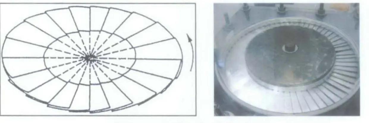
The swirl motion in SFB is caused by the annular spiral distributors whereby there are number of blades arranged in spiral motion. The openings between the blades allow the air to flow from the plenum chamber into bed. The inclined motion of the air causes the swirl of the particles inside the SFB. The concept of annular spiral distributor is inspired from Ouyang and Levenspiel (1986) work where in they proposed a spiral distributor for swirl motion. They found out from their experiment that pressure drop across the spiral distributor is from 1 to 2 orders of magnitude smaller than for the sintered plate tested; however, this pressure drop increases more rapidly with an increase in gas velocity than for the sintered plate. Vinod eta!. (2010) in his paper "Study of the Fluid Dynamic Performance of Distributor Type in Torbed Type Reactors" said that the percentage useful area of the distributor was about 95 in the inclined blade type distributors, while it was 64 in the perforated plate type distributor.
Sreenivasan ( 1995) has conducted experiments in a SFB with a distributor capable of giving swirl motion to the bed particles. In this experiment, the distributor was made of a number of blades that are truncated sectors of a circle with each blade inclined at
0
an angle of 12 to the horizontal. Since hollow metallic cone was placed at the centre of the bed to avoid particle accumulation, the area at the centre of the distributor which was covered by the cone was not utilised. Hence the static bed height will be more for a given weight of the material than in a conventional fluidized bed.
Certain drawbacks in conventional fluidized bed which lead to development of SFB and other fluidization beds are limitation in gas flow rate to avoid elutriation in gas- fluidized beds, and limitations on particles size, size distribution and particle shapes.
However, SFB provides an efficient contact between gas and particles compared to conventional fluidized bed. Conventional bed requires high pressure drop for fluidization as compared to SFB where it emphasize on quality fluidization. Besides that, due to the cross flow of the particles, no stable jet formation occurs in the SFB.
The toroidal motion in the bed mixes the particles in the radial direction. The gas
velocity can be increased to high values with little elutriation. In addition, SFB have distinct advantages in drying of agriculture produce. (Paulose M.M, 2006, pg 2).
These are the advantages of SFB over conventional fluidized bed.
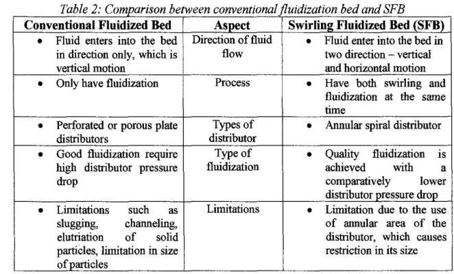
The table below illustrates the comparison between conventional fluidized bed and SFB:
Table 2: Comparison between conventional fluidization bed and SFB
Conventional Fluidized Bed Aspect Swirling Fluidized Bed (SFB)
•
Fluid enters into the bed Direction of fluid•
Fluid enter into the bed in in direction only, which is flow two direction - verticalvertical motion and horizontal motion
•
Only have fluidization Process•
Have both swirling and fluidization at the same time•
Perforated or porous plate Types of•
Annular spiral distributordistributors distributor
•
Good fluidization require Type of•
Quality fluidization IShigh distributor pressure fluidization achieved with a
drop comparatively lower
distributor pressure drop
•
Limitations such as Limitations•
Limitation due to the useslugging, channeling, of annular area of the
elutriation of solid distributor, which causes
partiCles, limitation in size restriction in its size of particles
Therefore, SFB has more advantages and applications compared to conventional fluidized bed. Since it has wider characteristics and applications, it is very much used in the industries.
2.3 Distributor Pressure Drop
Distributors are a series of blades that has been arranged in spiral motion. These distributors' blades are arranged in an inclined angle to allow gas or air to pass trough. As the name applies, it is used to distribute the air or gas uniformly inside the SFB. Therefore, it is one of the crucial components in the fluidized bed and it also influences the process undergoing inside the bed.
Type of distributor used in this experiment is annular spiral distributor, where the blades are arranged in the clockwise direction and hence the air flow is also in clockwise direction. The figure below shows the example of an annular spiral distributor; where the flow is in counter clockwise direction and the annular spiral distributor used in this experiment respectively.
Figure 4: Annular spiral distributor
Paulose M.M (2006) says that a good gas distributor shall possess the following qualities:
1. Have low distributor pressure drop at the operating velocity so as to minimize the power consumption.
2. Be strong enough to withstand both thermal and mechanical stresses.
3. Ability to prevent particle flow back to the plenum chamber at low airflow.
4. Have minimum particle attrition.
5. Ability to prevent distributor attrition.
Distributor pressure drop is very important since it will determine the air flow inside the fluidized bed. If the pressure drop is very low, the air will enter the bed in the zone of lowest pressure drop and it will cause a non-uniform distribution of air flow inside the bed. Therefore, distributor design is very important.
Paulose M.M (2006) says that ratio of the distributor pressure drop to the bed pressure drop (R) is generally considered for the design of distributors in conventional bed. Hiby (1967) mentioned that the minimum ratio of distributor to bed pressure drop, depends not only on the distributor type but also on the fluidized particles, the bed depth, the superficial gas velocity, bed aspect ratio and even the
percentage of uneven distribution which can be tolerated. Few researchers have come out with values for R according to material used and different types of plates used.
Meanwhile, Sathyamurthy et a!. (1977) observed that the number of orifices or percentage open area is determined by the gas flow rate, bed height, bed material and type of distributor. He also observed that a higher bed pressure drop is required to operate all orifices in case of finer size particles. Whitehead (1971) stated that it is dangerous to postulate universal rules for distributor pressure drop in terms of a fixed value for the ratio and to attempt to apply them to all situations.
Thus, distributors are one of the important components in SFB since its pressure drop very crucial in providing a uniform air flow inside the fluidized bed.
2.4 Bed Pressure Drop
In fluidized bed processes bed pressure drop is crucial as it determines the power required. Bed pressure drop is the pressure difference between total pressure drop and distributor pressure drop. Therefore, it is the pressure of the bed particle, which shows the behavior of the bed particles. Ergun (1986) has established that the pressure drop in a fluidized bed is due to the simultaneous kinetic and viscous energy losses. Therefore, he had done experimental and analytical studies and came out with an equation called Ergun's equation. The equation is:
~&
L
Where:
- Pressure loss
Viscous energy losses
- Effective diameter of particles - Gravitational Constant
f! -Absolute viscosity of fluid
Kinetic energy losses
G -Mass-flow rate of fluid L -Height of bed
1§1 -Fractional void volume
Urn -Superficial fluid velocity assured at average pressure
Above equation has been examined from the point of view of its dependence upon flow rate, properties of the fluids, and fractional void volume, orientation, size, shape and surface of the granular solids. However, Ergun considered the following factors in his equation.
a) Rate of fluid flow
b) Viscosity and density of the fluid c) Closeness and orientation of packing d) Size, shape and surface ofthe particles
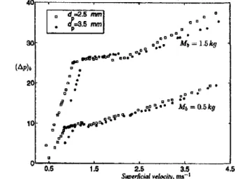
Sreenivasan and Raghavan (2002) said a striking feature that distinguishes the swirling bed from a conventional fluidized bed is that, the bed pressure drop in the swirling mode, (t.p )b,, increases with air velocity. This is because the bed pressure is proportional to the centrifugal weight of the bed. They conducted experiment in swirling bed for two different size of spherical PVC particle. The founding of the experiment is that the pressure drop in the swirling regime is not constant, but increases with gas flow rate and also proposed that the pressure drop increases with centrifugal weight of the bed or the angular velocity of particle. During their experiment, they came across the following regimes in their bed:
a) Bubbling
b) Wave motion with dune formation c) Two-layer fluidization
d) Stable swirling
Both researchers model the pressure drop, (t.p)b,s, m the swirling regime of operation. Their principle assumptions are:
a) The bed is a single swirling mass of uniform angular velocity
b) The angular velocity of the gas at the free surface of the bed IS
approximately equal to the mean angular velocity of the bed
Figure below shows the result of the experiment carried out by Sreenivasan and Raghavan. Their experiment predicts the pressure drop in the packed regime using Ergun equation to within 20% of the experimental values.
··r-::=;;:;::;;;;;_;;;--~----:~
I
o• d ..a.s mm1
<.a.s
mm1(Ap), 20
10
0 0.5 1.5
0 0
2.5 3.5 4.5
S~qUrficial ~l«il)', ms-1
Figure 5: Experimentally obtained bed pressure drop, in mm of water
From their experiment, the pressure drop of fluidization may be expressed as:
Meanwhile, the pressure drop in the swirling region can be predicted using the following equation:
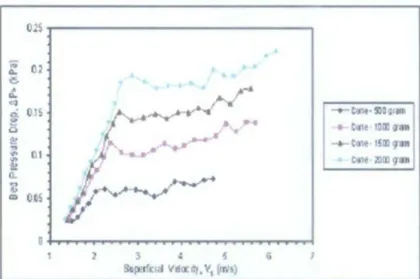
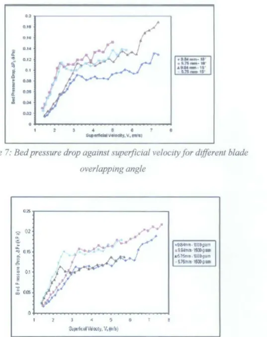
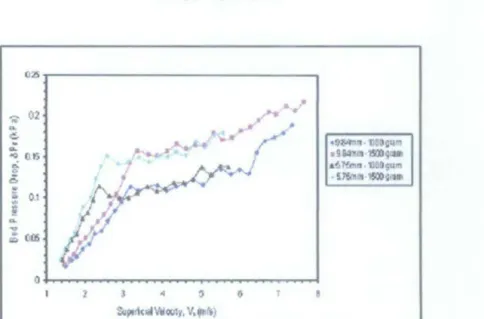
In another research, Mohd Faizal eta! (2010) found that the pressure drop of the bed increased with superficial velocity after minimum fluidization, in contrast with a conventional fluidized bed. They also found that the blade geometry has less effect on bed performance, compared to fraction of open area and particle size. This experiment was carried out to know the influence of the superficial velocity, bed weight, blade overlapping angle and number of blades on the bed pressure drop. The results of the research are shown in the figures followed.
025
.
A; 02
..
• 0'0.
. ••
~ • • • 4 • . . •
"'
......
Cl fr-. ·
0 0.15 -.-tollt·!lG•;<Mr
..
-•-t•Jlt 10000'8a e
..
-+-t•l,t • 1500 •JD"' 01 .. til1~·l!l00g'8
0.. 2t
... .. ~
CD 0.05
D
1 2 l 0 s 6 }
S~p;rf(tcl VIla: !lf, V, (ITJS)
Figure 6: Bed pressure drop against superficral velocity for variable bed loading
0.2 O.tt
o••
i. o ....
4 O.IZ
1
!i 0 Ii
ODel
OMJ 0.0.
O.!U
0
4 G
• ' •
S,...tt11clttll-f. v, tmt81
Figure 7: Bed pressure drop against superficial velocity for different blade overlapping angle
025
02 --.,··
-;;- J , . / _,
....
~ ~ ~
... / /
•0~~·1l:3~q~... . ~~ J
I 9~r.t· :t500g<•ll~
..
Ot;· ~
a!i 7!mn .1)Q~gu"'0 .,. f .... • S1'$11U!t·:l51.:0~1·11
~ 0.1
''"'
.;
;J ~~...
....;, l~
~ CC6
(. .r;t
0
I I 3
.. ,
(i ~ a$.pt1<..,VIG01y, V,~l\)
Figure 8: Bed pressure drop against superficial velocity for different bed weight
OA 035
i OS
e ~ Oll
!
02i
O.UCl. ! 01
l
oos0
2 3 4 s
• • '
~IIIVtloclly. v,cw•>
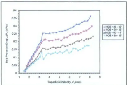
Figure 9: Bed pressure drop against superficial velocity for different number of blades
K.V.Vinod et al (2010) studied about the bed pressure drop as a function of superficial velocity by using three types of distributor, which are inclined blades in a single row, perforated plate with inclined holes and inclined blades on three rows.
Their experiment finding reveals that for each bed weight studied, the bed pressure drop was almost constant after minimum fluidizing velocity of about 1.2m/s. The results of the experiment are shown in the Figure 10.
30
i • J 25
0 E 10 E .!: 1S
! "
e , .
,
Q.cB 5
05 1 15 2 25
Superficial velocity n rmec
L--~~~--=-- I l l
.. "
. •
l! .. J
~
.
.£ •
;; g. !
.
"
..
: ! ..
Q.
'i I
Ill
·~~~~~~~~~~~
0 u u u
Supertlc:lal VelOcity In ni/Sec
U: O.N Ul 1.11 1.1
Superllclll velocity In m/Sec
Figure /0: Variation of bed pressure drop with superficial velocity for the inclined-blade three-row, inclined-blade single-row and perforated plate with
inclined hole type distributor respectively
Raghavan and Vi nod (20 11) in their research on operation of a swirling fluidized bed quoted that the bed pressure drop first show an upward trend and then reaching after a particular peak value it start decreasing. This may be attributed to the fact that the bed pressure drop will fall as the resistance from the bed decreases. Besides that, they said that the peak in the bed pressure drop can also be explained as being due to the additional energy required for rearrangement of the 'locked' particles.
In this research, the variation of bed pressure drop was shown against superficial velocity. In order to find the superficial veloctty, author measures the pressure drop in orifice meter and used the following equations to calculate the flow rate in m3 /s and superficial velocity in mls respectively.
Flow rate = cd X -./ 2 X g X ~p 8lf X Orifice Area
~ 1- (d/D)4
Vsuperficiat =Flow rate (m3/s) Bed area (m2)
In case of SFB, the bed pressure also occurs due to the rearrangement of particles during fluidization. When the gas enters the bed trough the distributor, the packed bed slowly gets fluidized and the bed expands The particles get lifted up and swirl in
the direction of the gas as illustrated in Figure 11. So some extra energy has to be spent to unlock the particles from the packed state in order to get them fluidized.
dJre;o.-
of-· ... -
Figure 1 1: Rearrangement process
Only few researchers had done research on bed pressure drop. However, their research usually will be a part of another research. No one had dedicated a research solely on bed pressure drop. Therefore, the author gets an advantage since her research is fully on the bed pressure drop and the parameters that influence the bed pressure drop.
3.1 Experimental Set Up
CHAPTER3
METHODOLOGY
The schematic diagram of the test set-up for this experiment is shown in the Figure 12. This test set-up consists of a Perspex cylinder, which forms the bed wall. The cylinder is mounted on the distributor. The type of distributor used in this test is flexible version of annular spiral distributor. It is a variant of the spiral distributor developed by Ouyang and Levenspiel (1986). Unlike in case of Ouyang and Levenspiel the blades are not welded at the centre for the sake of flexibility in changing the blades with different overlapping angle during the experiment. The trapezoidal shaped blades are made of lmm Aluminium and there are sixty of them.
The blades are arranged on stepped rings, an outer and inner, with steps machined at an angle of 10° to the horizontal. The blades are held intact by two other rings, an outer and inner, on the top. The inclined overlapping blades direct the fluidizing air as desired. A thin cylindrical shape metal of 5mrn thick is screwed at the centre of the bed above the stepped rings in order to keep the blades in place tightly. The stepped rings and the blades are arranged around the Bakelite. The blades and annular spiral distributor used in this experiment is shown in the Figure 14 and Figure 16 respectively.
Both the Perspex cylinder and distributor are mounted on the plenum chamber by using bolts and nuts. The author did not prefer using permanent joint because it will be easier to use bolts and nuts whenever the author needs to change the distributor blades. The plenum chamber is a hollow cylinder with a hole at one of its side for the air entry. A flange is welded to the plenum chamber at the hole in order to connect the chamber to the pipes. The chamber is connected to the blower with PVC pipes.
There are two paths for the air to flow, which are larger flow and lower flow. This flow is controlled by two butterfly valves. If the air flows from the blower through
the first butterfly valve, the second butterfly valve will be closed and vice versa. Two orifice plates are mounted at middle of the pipe connecting the blower and plenum chamber to measure the air flow rate.
A hollow metal cone is centrally located at the base of the bed. This cone causes the superficial velocity of the air decreases continuously from the distributor to the free surface of the bed. Besides that, it also eliminates the 'dead zone' at the centre of the bed (Sreenivasan and Raghavan, 2002). Then, three pressure tappings, P1, P2 and P1 are provided on the set up to measure the pressure drops using digital manometer. P1, and P 2, are on the Perspex bed wall while P 3 is on the plenum chamber wall below the distributor plane. The complete and overall experimental set up is shown in the Figure 18.
370 )( 370
- ---t---1
----.. -··-··-··--7"1---:-! ---~,
J
Airinlcl i. \1>310 .i
Column
Bedwlll
Diatribouor
Windbox
Figure 12: Experimental Test
Figure 14: Shape of blade used in this experiment
.... ~-Perspex
Cylinder
~~--Plenum
Chamber
Figure 13: Perspex Cylinder and plenum chamber which make up the
bed
.•• t~c.~ ..
Figure 15: Blade overlap angle
Bakelite
nng
Figure 16: Annular Spiral Distributor
Figure 17: Digital Manometer
Figure 18: Overall Experimental Set up
21
Thin cylindrical shape metal
rmg
3.2 Procedures of the Experiment
3.2.1 Flow chart
The experiment was conducted with three different particles with three different weights and four distributor blade overlapping angles. The detailed explained
Research and literature reVlew were
~ conducted to have better understanding of SFB concept. Author read journals published about SFB to know about the development in SFB.
The effect of particle stze and distributor blade overlap angle on bed pressure drop in SFB has not been explored so far. Thus, author chooses these two parameters m her experiment.
ith the help of a PhD student, author design the experiment set up.
uthor procure material needed for her experiment set up such as aluminium sheet, PVC pipes and etc and get endorsed by her supervisor.
Equipment parts such as plenum chamber were fabricated by fabricator and assembly of the set up was done by the author with the help of a PhD experiment procedures are
in the following section.
JL
srudentThe results were tabulated and Trial runs were conducted in order to analyzed using graphs. Detailed results test the experiment set up.
description is shown in result section.
3.2.2 Procedures
1. Blades of overlap angle go are arranged on the mner stepped ring at Bakelite and the outer stepped ring is placed on the blades to keep the blades m place.
2. The thin cylindrical shape metal of 5mm thick is screwed at the centre of the bed above the stepped rings in order to keep the blades in place tightly.
3. Then, the central cone is screwed at the center of the bed.
4. Next, the Perspex cylinder is screwed with bolts and nuts to the plenum chamber.
5 The experiment set up is tested with the blower switched on to confirm the experiment set up works well without any failure or leakage.
6. Blower is switched on again.
7. Then, the distributor pressure drop, (P2- P3) is measured at different air flow rates.
8. The air flow rate is varied progressively using a butterfly valve.
g_ The air flow rate is measured using an orifice flow meter.
10. The bed is loaded with 500g cylindrical particle.
11. The total pressure drop, P 3, IS measured for different air flow rate.
12. Then, the experiment is continued with 750g and IOOOg of cylindrical particle.
13. The experiment is repeated for blade overlap angles of 12°, 15' and 18° with spherical and oval shape particles.
Basically, the experiment was conducted in batch with the following condition:
; Particle shape: Spherical (lrnm), Cylindrical (UO =3.5), Oval (2mm minima dia.) ,. Particle weight (g): 500, 750, 1000
~ Blade overlap angle: go, 12 , 15o & 18°
23
Ftgure 19: Cylmdrical, Oval and Sphencal particle respecttvely
All the readings were inserted in a Microsoft Excel sheet. Finally, the bed pressure drop is the pressure difference between the total pressure drop and distributor pressure drop i.e. (P1 - P3). Graphs were generated to analyze the effect of particle shape and blade overlap angle on bed pressure drop. It will be discussed in results section.
3.3 Project Planning (Gantt chart)
Milestone for Final Year Project I
No Detail/Week 1 Selection of project topic
Confirn of project 2 topic
3 Literature review studies
4 Submission of preliminary report
5 Fabrication &
!::;.,.p.,;imental set up 6 Trial tests
7 Submission of progress report
8 Seminar
9 Initial Experiments on the setup
ll Submission of interim report
12 Oral p~c:.~:a•Lauuu
l l 3 4 ~
•
e
Suggestedmilestone Process
6 7 8 9 10 II ll l3 14
tlll
I~ •
• -= •
During Study Week
Figure 20: Gantt chart of FYP I
Milestone for Final Year Project D
_No Deuailr .. -•-n~~~:~~:a
1 Cylindrical Shape experiment 2 Spherical Shape
experiment
3 Oval Shape""'·""' uuvm
4 Result AnalySIS
5 Progress report Submission
6 Repeat the experiment 7 Result Analysis 8 Poster exhibition
9 Submission of dissertation (soft)
10 Oral .., • .,.,,.mtation
11 Submission of dissertation(hard)
. 1
3 4 5• Suggested milestone Process
6 7 8 9 10 11 ll 13 14
j.
! =c
•
•
•
7 Days after Oral Presentation
Figure 21: Gantt chart of FYP 11
25
4.1 Results
CHAPTER4
RESULTS AND DISCUSSIONS
Although there are many feasible permutations of results are possible from the data acquired from the experiment, only a few are presented here.
4.1.1. Effect of Particle Shape on Bed Pressure Drop
4.1.1.1. Distributor Blade Overlap Angle of 9°
Bed Pressure Drop Variation for bed weight of SOOg 16.00 1
0 14.00
l
2! E 12.00
.§. 10 00
8' .
~ 8.00
~ ~ 6.00
~ 4.00
"0
~ 2.00 0.00
~cv_sooa
-e-sp_SOOg ...,.._Ov_SOOg
0.00 0.01 0.02 0.03 0.04 0.05 0.06 0.07 0.08 0.09 Supertklalvelodty, u (m/s)
Figure 22: Variation of bed pressure drop with Vsuperfic1at wtth blade overlap angle of9 for different shape of particle wtth bed wetght of500g
16.00 014.00
...
I 12.00!. 10.00 0
..
~ 8.00~ 6.00
0.. ~ 4.00
,
~ 2.00 0.00
Bed Pressure Drop Variation for bed weight of 750g
-+-Cy_750g - Sp_750g .,.._ov_750g
0.00 0.01 0.02 0.03 0.04 0.05 0.06 0.07 0.08 0.09 SuperfklaiVeloclty, u(m/s)
Figure 23: Variation of bed pressure drop with Vsuf'<!rficial wlfh blade overlap angle of9ofor different shape of particle with bed weight of750g
22.00 20.00 0 18.00
...
%E 16.00
!. 14.00
Q. e 12.00
0
.. ..
:3 10.00 8.00 ::1 ~ 6.00,
0.. ID..
4.002.00 0.00
1
Bed Pressure Drop Variation for bed weight of 1000g
r
- + -Cy_lOOOg
~Sp_1000g
- r -ov_lOOOg
0.00 0.01 0.02 0.03 0.04 0.05 0.06 0.07 0.08 0.09 Superficial Velocity, u(m/s)
F1gure 24: Vanation of bed pressure drop with Vsuperficial wlfh blade overlap angle of9 for different shape of particle with bed weight of IOOOg
4.1.1.2.
tr
Distributor Blade Overlap Angle16.00 -14.00 • 0
...
I
12.00!.10.00
e Q.
0 8.00
" ~ ::: 600
"
~ 400
~ 2.00
0.00 0.00
Bed Pressure Drop variation for bed weight of SOOg
O.Q2 0.04 0.06 0.08 0.10 0.12
SuperfklaiVelocity, u(m/sl
-+-Cy_SOOg
....,_Sp~SOOg
-..-ov_SOOg
0.14 0.16
Figure 25: Variation of bed pressure drop with Vsuperficial with blade overlap angle of 12 for different shape of particle with bed weight of 500g
27
1800 - 16.00
;! 0 14 00 l
_g E 12.00
~ 1000 Q
~ 8.00
5 6.00
"'0
E
4.00~ 2.00
Bed Pressure Drop Variation for bed weight of 750g
~Cy_750g
- e -5p_750g - -ov_750g
000 ,_..~~~
0.00 0.01 0.02 0.03 0.04 0.05 0.06 0 07 0.08 0.09 SuperflclaiVelocity, u (m/s)
Figure 26: Variation of bed pressure drop wllh Vsupetflc,al wllh blade overlap angle of 12 for different shape of particle wtlh bed weight of750g
22.00
0 20.00
~ 18.00
~ 16.00 -; 14.00
2 12.00
~ 10.00 !
~ 8.00
~ 6.00
0..
"'0 4.00 '
~ 2.00
Bed Pressure Drop Variation for bed weight of lOOOg
~Cy_lOOOg
- Sp_lOOOg ...,_Ov_lOOOg
0.00 ~~~~
0 0.01 0.02 0.03 0.04 0.05 0.06 0.07 0.08 0.09 Superficial Velocity, u (m/s)
Figure 27: Variation of bed pressure drop with Vsupetflcial with blade overlap angle of 12 for different shape of particle with bed weight of I OOOg
4.1.1.3. 15° Distributor Blade Overlap Angle
Bed Pressure Drop Variation for bed weight of SOOg
18.00
0 16.00
'i
N 1400 .§. 12.00e-
10.00Q
~ 8.00
~ 6.00
~ '0.. 4.00
"'0
-+-Cy_SOOg - - -Sp_SOOg
,~ 2.00
0.00
..,._Ov_SOOg
0 0.01 0.02 0.03 0.04 0.05 0.06 0.07 008
Superficial Velocity, u (m/s)
Figure 28: VariatiOn of bed pressure drop with V,1,petflcial wzth blade overlap angle of 12 for different shape of particle with bed weight of 500g
20.00 - 18.00 0 ~ 16.00 E E 14.00
-a:
0 12.00C5 10.00
~ 8.00
::l lll 6.00
..
tl Q.~ tl 4.00
ell 2.00 0.00 0
Bed Pressure Drop Variation for bed weight of 750g
T T
0.01 0.02 0.03 0.04 0 OS 0.06