i
I declare that I have been done reading this report and in my opinion, this report fulfill the condition in all aspect that must be in project writing as need in partial fulfillment
for Bachelor of Mechanical Engineering ( Thermal – Fluid )
Signature : ………
Supervisor Name : En.Safarudin Gazali Herawan
ii
INVESTIGATION OF SHAFT SPEED CAUSE BY TURBO SYSTEM IN VEHICLES
CHE MOHD ELYAS BIN CHE OMAR
This report had been done in partial fulfillment for
Bachelor of Mechanical Engineering (Thermal – Fluid)
Faculty of Mechanical Engineering Universiti Teknikal Malaysia Melaka
iii
“I declare that this report had been done originally from me except some of them where I have been explain each one of them with its sources”
Signature : ………
Name : Che Mohd Elyas Bin Che Omar
iv
Especially to my beloved parents, My respectfully lecturers, Also my faithfully friends,
v
ACKNOWLEDGEMENT
First of all, I would like to thank to our God Allah S.W.T. because with His permission I can finish a “Projek Sarjana Muda” (PSM ) to complete the requirement for graduation.
Secondly, I would like to thank to my supervisor, Mr Safarudin Gazali Herawan, Lecturer of Mechanical Engineering Faculty in UTem (Thermal – Fluid), for giving me the opportunity doing my PSM under his supervision. I also would like to thank to him for teaching me more in mechanical engineering subjects especially works for my topic which is effect of turbo system in the automotive exhaust gas system. He also guided me and given advised based on his experience during my progress of this project. I have learned many new things from him.
I would also like to thank to all of lab assistant that involved in this project. I would appreciate all their effort to make this project happen. Thank also for their cooperation with me since the progress of this project for using any of their lab for my experiments.
I would also like to thank to all my friends especially class of 4 BMCT (G2) for being kind and helpful to me until the project done. They have been helping me doing research for this project.
vi
ABSTRACT
vii
ABSTRAK
x
4.5 Collaboration between throttle angle and resistance 39
xi
REFFERENCE 49
BIBLIOGRAPHY 50
APPENDIX A 51
APPENDIX B 51
APPENDIX C 52
APPENDIX D 52
APPENDIX E 53
APPENDIX F 53
APPENDIX G 54
APPENDIX H 54
xiii
4.3 Graph pressure versus engine speed 32
4.4 Graph temperature versus engine speed 33
4.5 Graph temperature versus engine speed 34
4.6 Graph temperature versus engine speed analysis 35
4.7 Graph shaft speed versus engine speed 37
4.8 Graph shaft speed versus pressure 38
4.9 Graph resistance versus throttle angle 40
4.10 Graph voltage versus torque 42
5.1 Mild steel shaft 45
xiv
LIST OF TABLES
NO. TITLE PAGE
4.1 Pressure data for natural aspirated engine 30
4.2 Pressure data for turbine system engine 31
4.3 Temperature data for natural aspirated engine 33
4.4 Temperature data for turbine system engine 34
4.5 Shaft speed data for turbine system engine 37
4.6 Throttle angle data 39
xv
LIST OF SYMBOLS
T = Temperature, Celsius ºC / Fahrenheit, F
n
= number of revolution per cycleVd = displacement volume (m³)
Wb = brake work of one revolution
N = Engine speed (rev/s)
T = Torque (N.m)
1
CHAPTER I
INTRODUCTION
1.1 Project background
2
1.2 Project significant
The significant of this project is developing a system recovery for the wasted energy in vehicles. This wasted energy has a potential to increase the efficiency of the engine and also get the better performance of the engine. From this recovery system, the electric energy can be produced for the future function such in hybrid car or used for electrical components in the car. The electric energy can be stored in one device such as battery and can be use for multi-function in vehicles that used electric as their energy source. So, it become suffer lose if this wasted energy did not been used for improvement and this project is very significant to the new era of automobile in our country with the increasing of petroleum price.
1.3 Objective
1. To investigate pressure, temperature, and shaft speed from turbo system in vehicle due to recovery of the wasted energy at exhaust manifold.
2. To study sensor contribution of throttle body and load cell.
1.4 Scope
In this research, the experimental for project must be developed and the results of the experiments analyzed. Below are the scopes for this project:
1. Installation of turbo system components.
3
1.5 Problem Statement
4
CHAPTER II
LITERATURE REVIEW
2.1 Turbocharger and Supercharger mechanism
Turbocharger and Supercharger mechanism are the same system, which is to increase the air volume into the combustion chamber.
2.1.1 Supercharger Mechanism
5
Superchargers are mechanically driven directly from the engine crankshaft and the speed of engine will running the compressor with the same speed. It can be powered mechanically by a belt, gear, shaft, or chain connected to the engine's crankshaft. The power to drive the compressor is a parasitic load on the engine output, and this is the major disadvantages compared to the turbocharger system. This is because, if the power output of the engine low, it cannot run the compressor with the optimum speed.
A major advantages of the supercharger us very quick response to throttle changes. Being mechanically linked to the crankshaft, any engine speed change is immediately transferred to the compressor. Nowadays, people have modified this system to be more efficient by running the compressor by using the turbine known as turbocharger system. So, the compressor did not add any load to engine.
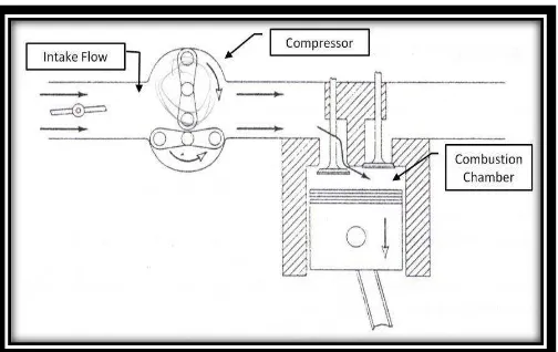
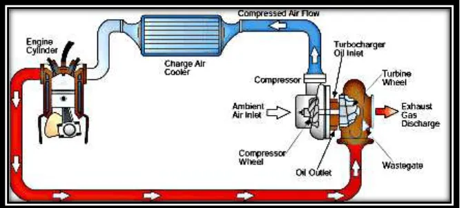
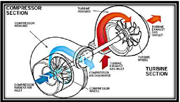
2.1.2 Turbocharger Mechanism
Figure 2.2: Compressor used to increase air pressure to engine. (Source: www.google.com)
6 pumps air into the cylinders. The compressor is a type of centrifugal pump; it draws air in at the center of its blades and flings it outward as it spins. In order to handle speeds of up to 150,000 rpm, the turbine shaft has to be supported very carefully. Most bearings would explode at speeds like this, so most turbochargers use a fluid bearing. This type of bearing supports the shaft on a thin layer of oil that is constantly pumped around the shaft. This serves two purposes: It cools the shaft and some of the other turbocharger parts, and it allows the shaft to spin without much friction. There are many tradeoffs involved in designing a turbocharger for an engine.
7
Figure 2.4: Power and torque curves of 1982 Datsun 280ZX (Source: Pulkrabek, 2004)
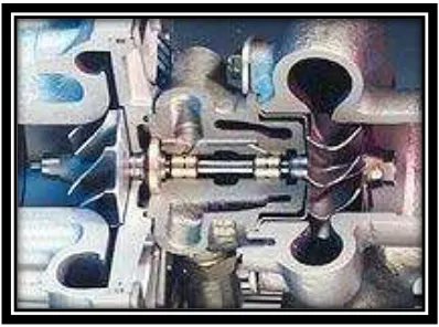
2.1.3 Turbocharger bearing system
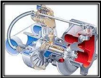
Figure 2.5: Turbocharger bearing system (cut-away model) (Source: www.turbodriven.com)
8
1,000,000 km for a commercial vehicle. Only sleeve bearings specially designed for turbochargers can meet these high requirements at a reasonable cost.
Radial bearing system
With a sleeve bearing, the shaft turns without friction on an oil film in the sleeve bearing bushing. For the turbocharger, the oil supply comes from the engine oil circuit. The bearing system is designed such that brass floating bushings, rotating at about half shaft speed, are situated between the stationary centre housing and the rotating shaft. This allows these high speed bearings to be adapted such that there is no metal contact between shaft and bearings at any of the operating points. Besides the lubricating function, the oil film in the bearing clearances also has a damping function, which contributes to the stability of the shaft and turbine wheel assembly. The hydrodynamic load-carrying capacity and the bearing damping characteristics are optimised by the clearances. The lubricating oil thickness for the inner clearances is therefore selected with respect to the bearing strength, whereas the outer clearances are designed with regard to the bearing damping. The bearing clearances are only a few hundredths of a millimetre.
The one-piece bearing system is a special form of a sleeve bearing system. The shaft turns within a stationary bushing, which is oil scavenged from the outside. The outer bearing clearance can be designed specifically for the bearing damping, as no rotation takes place.
i. Axial-thrust bearing system
9
ii Oil drain
The lubricating oil flows into the turbocharger at a pressure of approximately 4 bar. As the oil drains off at low pressure, the oil drain pipe diameter must be much larger
The centre housing must be sealed against the hot turbine exhaust gas and against oil loss from the centre housing. A piston ring is installed in a groove on the rotor shaft on both the turbine and compressor side. These rings do not rotate, but are firmly clamped in the centre housing. This contactless type of sealing, a form of labyrinth seal, makes oil leakage more difficult due to multiple flow reversals, and ensures that only small quantities of exhaust gas escape into the crankcase.
Figure 2.6: Water-cooled bearing housing (Source: www.turbodriven.com)