UNIVERSITI TEKNIKAL MALAYSIA MELAKA
SINTERING CHARACTERISTICS OF INJECTION MOULDED
COMPONENTS USING WASTE RUBBER BIOPOLYMER
This report submitted in accordance with requirement of the Universiti Teknikal Malaysia Melaka (UTeM) for the Bachelor Degree of Manufacturing Engineering
(Engineering Materials) with Honors.
By
NURHASHIMA BINTI SHAFIEE
DECLARATION
I hereby, declared this report entitled “Sintering Characteristics of Injection Molded Components using Waste Rubber Biopolymer” is the results of my own research except
as cited in references.
Signature : ……….
Author’s Name : NURHASHIMA BINTI SHAFIEE
APPROVAL
This report is submitted to the Faculty of Manufacturing Engineering of UTeM as a partial fulfillment of the requirements for the degree of Bachelor of Manufacturing Engineering (Engineering Materials) with Honours. The member of the supervisory
committee is as follow:
i
ABSTRACT
ii
ABSTRAK
iii
DEDICATION
iv
ACKNOWLEDGEMENTS
v
2.3.1 17-4 PH Stainless Steel 12
2.4 Binder System 13
2.4.1 Paraffin Wax 15
2.4.2 Thermoplastic Waste Rubber 15
2.4.3 Stearic Acid 16
vi
2.6 Sintering Practice 18
2.6.1 Effect of Sintering Temperature and Atmosphere 19
2.7 Density Measurements 20
3.2.1 17-4 PH Stainless Steel Powder 25
3.2.2 Binder 27
3.6 Morphological Observation 38
3.6.1 Scanning Electron Microscope (SEM) 39
3.6.2 Optical Microscope 39
4.0 RESULTS AND DISCUSSION
vii
4.2 17-4 PH Stainless Steel Powder Characterization 41
4.3 Observation on Sample Preparation Process 42
4.3.1 Injection Molding 43
4.3.1.1SEM Observation of Green Body 45
4.3.2 Debinding 47
4.3.2.1Study on Kinetic Solvent 48
4.3.3 Sintering 51
4.4 Shrinkage Observation 51
4.5 Critical Property Analysis - Tensile Test 55
4.5.1 Fracture Surface Morphology of Tensile Specimens 58 4.5.2 Optical Microstructure of Tensile Specimens 63
4.6 Density 66
4.7 Hardness 67
5.0 CONCLUSION AND RECOMMENDATION
5.1 Conclusion 69
5.2 Recommendation 71
REFERENCES 72
APPENDIX
A Gantt chart PSM I B Gantt chart PSM II
viii
LIST OF TABLES
2.1 Chemical composition of alloy 17-4pH stainless steel 12 2.2 Typical mechanical properties of 17-4pH stainless steel at high
temperature [tempering temperature = 6000C] 13
3.1 Chemical composition of 17-4 pH stainless steel powder 28
3.2 Varied heating rate and soaking period 33
4.1 Dimensions and shrinkage percentage of samples 53
4.2 Tensile properties of each specimen groups 56
ix
LIST OF FIGURES
2.1 Flow chart illustrating major processing steps in MIM process 7
2.2a Feedstock pellets for molding 9
2.2b Granulate feedstock for molding 9
2.3 Classification scheme for the various ferrous alloys 10 2.4 Conceptual visualization of interplay between the chemistry,
properties, microstructure and processing for PIM operation 18
2.5 Density measurement apparatus 21
2.6a The SEM micrograph of a sintered specimen’s fractured surface; the mid-part of the specimen made with the optimal sintering and molding
conditions 23
2.6b The SEM micrograph of a sintered specimen’s fractured surface; the mid-part of the specimen made with the worst sintering and molding
conditions (magnification 400x) 23
2.7a SEM micrograph of feedstock without extrusion 23
2.7b SEM micrograph of feedstock with extrusion 23
3.1 17-4 PH stainless steel metal powders 25
x
3.6 MCP HEK-GMBH vertical injection molding 30
3.7 Solvent extraction process 31
3.7a Water bath model Memmert 31
3.7b Immersion of green samples in heptanes using water bath 31
3.8 Lynn furnace 32
3.9 The heating profile of thermal pyrolisis process 32
3.10 Multi-atmosphere sintering furnace 33
3.11 The heating profile of sintering operation 34
3.12 Measuring of sintered specimens 35
3.13 Density measurement 36
3.13a Specific gravity meter 36
3.13b Specimen weighted in the air 36
3.13c Specimen weighted in water 36
3.14 Universal Testing Machine (UTM) 37
3.15 Microvickers hardness tester 38
3.16 Scanning Electron Microscope (SEM) 39
3.17 Optical Microscope (OM) 40
4.1 SEM micrograph of the 17-4PH stainless steel used in the feedstock
preparation 42
4.2 Granulated feedstock 43
4.3 Green body 44
4.4 Dimension of green body 45
4.5 The scanning electron micrograph of the green body after injection
molding; (a) fracture and (b) outer surface 46
4.6 Graph of main binder removal percentage versus time with the
morphological changes at fracture surface of sample at; (a) 10 minutes, (b) 60 minutes, (c) 120 minutes and (d) 300 minutes 50
4.7 Sintered sample 51
xi
4.9 Shrinkage percentage for different group of sample 54 4.10 Tensile strength of sample at different sample set 56 4.11 Tensile modulus of sample at different sample set 57 4.12 The SEM images of fractured surface of the samples that used 50C/min
of heating rate for three different soaking period; (a) 30 minutes,
(b) 60 minutes and (c) 120 minutes 60
4.13 The SEM images of fractured surface of the samples that used 100C/min of heating rate for three different soaking period; (a) 30 minutes,
(b) 60 minutes and (c) 120 minutes 61
4.14 The SEM images of fractured surface of the samples that used 150C/min of heating rate for three different soaking period; (a) 30 minutes,
(b) 60 minutes and (c) 120 minutes 62
4.15 Actual density of 17-4PH sintered samples for different heating rates and
soaking periods 66
4.16 Actual hardness of 17-4PH sintered samples for different heating rates
xii
PIM - Powder Injection Molding
PM - Powder Metallurgy
Tg - Glass Transition Temperature
TPWR - Thermoplastic Waste Rubber
UTM - Universal Testing Machine
WR - Waste Rubber
xiii
LIST OF SYMBOLS
g/cm3 - gram per centimeter cube
mm - millimeter
rpm - revolution per minutes
Vol. % - percentage of volume
Wt. % - percentage of weight
µm - micron meter
µPIM - Micro Powder Injection Molding 0
C - Degree Celsius
0
C/min - Degree Celsius per minute
1
CHAPTER 1
INTRODUCTION
1.1 Background of Study
Nowadays, major challenges in Powder Metallurgy (PM) research field are design complexity and flexibility of the fabrication process, with a low cost consideration. Researchers have tried to propose the best solution to fulfill the extensive industrial requirement. There are many improvisation and development in the field of powder metallurgy. One of the new invented methods is to introduce the very recent and innovative powder metallurgy route by combining the concept of plastic injection molding together with the utilization of the metal powder feedstock. Such a unique method mentioned is the Metal Injection Molding (MIM). Basically, this process is more complicated compared to the plastic injection molding process. The process is based on the use of fine powder particles mixed with the small quantity of wax binders and/or thermoplastic polymer to form the feedstock that can be molded (German and Bose, 1997).
2
characteristics of the starting materials; the powder and the binder are critically important to the overall success of this process.
The optimum powder loading should be applied as it will affect the whole process while the feedstock has to be homogenous as possible made by intensive mixing of metal powder and the binder. The optimum powder loading applied in this study is in accordance to the previous research done by Gulsoy et al., (2007) and Ye et al., (2008).
Once the powder formulation has been established, further concern will be given to the ingredient mixing. The uniformity of the feedstock is crucial, since most inhomogenities condition cannot be corrected in the subsequent processing step. The best mixing occurs with high shear, but not to the point where the higher mixing shear damages the particles or overheats the binder. A properly mixed material will consist of homogenous powder dispersion in the binder with no internal porosity or agglomerates. Inhomogenities results in nonuniform viscosities, uneven molding and difficulties at the sintering stage (Klar and Samal, 2007).
Ideally, the feedstock design must be adequately considered the easiness of molding and strict control over the final dimensions. To achieve this situation, the feedstock used must have low molecular weight polymer binders as to reduce viscosity and to ease the molding process. If there are no voids or pores present in the feedstock, there are sufficient binders to fill in all interparticle spaces. Several defects that commonly occur are surface wrinkles, binder separation, weld lines, sink marks, flashing and unmature shot (Norhamidi et al., 2002).
3
vapor pockets. Alternatively, when the pores are partially open, the capillary forces resist distortion as the binder softens. Thus, progressive stepwise removal of the binder is mandatory to hold the component shape.
Final step involved in MIM process is sintering, which take place at high temperatures in order to bond the particles together. Sintering is a thermal treatment for bonding the particles into a coherent, predominantly solid structure via mass transport events that often occur on the atomic scale (German, 1996). The binder in the molded part that produces via injection molding process is removed through the solvent extraction prior to the thermal pyrolisis. The thermally debound part or the brown part still can retain the shape due to the friction among the powder particles even though all the binder has been removed at the earlier stage. Hence, this part is very fragile and needs to be handled carefully for the next sintering process which later performs to achieve desired final mechanical, physical and chemical properties. High final density is important for the optimization of the desired attributes. The final properties of the product can be further improved with additional heat and mechanical treatments.
1.2 Problem Statements
4
are homogenously filled with the binder. However, it is very difficult to get that kind of homogenous ideal powder and binder mixture condition (Li et al., 2007). Usually, the method for removing the binder is by thermal debinding that is a major controlled step in the MIM process. However, the great quantity of gas is produced by the evaporation and degradation of the binder which later produces many defects, such as bubbles and cracks in the molded parts. Thermal debinding process also consumes quite a long duration of operation (Li et al., 2003). Besides, the other aspect that should be considered is related to the component shrinkage and warpage. They are very low during the injection molding step and increases significantly during the debinding and sintering steps. As a result, the components may be out of design tolerances or, in the worst case; it may be cracked, excessively warped or chemically incorrect with a very poor density (Heaney and Spina, 2007). In view of that, a new binder system which is thermoplastic waste rubber (TPWR) will be developed as to improve these processes and to encounter major drawbacks of this process. The uses of waste rubber as novel binder system in the MIM processing to replace natural rubber is receiving great attention, due to the advantage of renewability, thermal stability and high shear viscosity. These waste rubber outstanding properties such as very weak adhesion between the waste rubber and polymer is due to the crosslinked structure of the waste rubber (Tan et al., 2008). Therefore, in this study, waste rubber will be utilized, formulates and evaluates as a new binder system for the MIM processing due to their above mention advantageously.
1.3 Objectives
The main objectives of this study are:
i. To investigate the sintering characteristics by determining the physical, mechanical and microstructural properties of the injection molded 17-4 PH stainless steel using new developed binder system that is waste rubber.
5
1.4 Scope of Study
This research was started with the selection of raw material and early characterization of its properties. The dimensional analysis of the powder particle will be carried out by utilizing the Scanning Electron Micrograph (SEM).
Next stage is the material processing which consists of four sequential processing steps of MIM processes. The first step is material formulation and mixing process to produce the granulate feedstock. Then, the next step will proceed into the injection molding process of the specimens. The feedstock after the mixing will be injection molded by using a vertical injection molding. After that, the third step will be followed by debinding of the molded specimens. At this stage, the binder system of these specimens will be removed from the green specimens. The process will be done in two separate stages which are solvent extraction method using water bath whereby the specimens will be immersed in heptanes, followed by the thermal pyrolisis that will be carried out by using the debinding furnace. Finally, the injection molded specimens will be sintered at varying heating rate by using the vacuum atmosphere sintering furnace. It is anticipated that the sintering process will gives strong interparticles bonds and removes or reduces the void spaces by densification mechanism. Hence, sintering causes substantial shrinkage in the MIM parts (German, 1996).
6
CHAPTER 2
LITERATURE REVIEW
This chapter reviews related study done by the previous researchers on powder injection molding through the metal injection molding method. This literature reviews are focused on the usage of the different binder system and its significant effects to the physical, mechanical and morphological structures of the metal injected samples that sintered at the various sintering parameters. The technical roles of the polymeric based binder system to assist the efficacy of the powder metallurgy operation will be further reviewed.
2.1 Powder Metallurgy
7 2.1.1 Metal Injection Molding
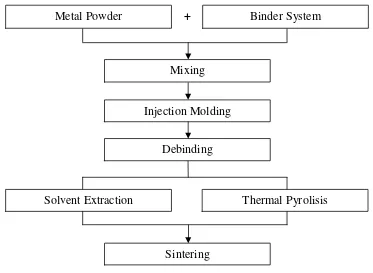
Technically, metal injection molding (MIM) that also can be referred as powder injection molding is using a feedstock that is high in their particle content. Figure 2.1 shows the major various steps involved in MIM; which are mixing, injection molding, debinding and sintering process (Beddoes and Bibby, 1990; German, 2007). The process begins with the mixing of the selected metal powder with the binders to produce the granulate feedstock. Then, the feedstocks are injection molded into the tensile bar through the injection molding machine that later produced green part of specimens. Next, the binder is removed from the green parts by a solvent extraction and thermal pyrolisis process. The remaining porous powder structures are sintered to near full density. The product may then be further densified, heat treated, or machined into the final shape (German, 2007).
Figure 2.1: Flow chart illustrating major processing steps in MIM process (Beddoes and Bibby, 1990; German, 2007)
+
Metal Powder Binder System
Injection Molding Mixing
Debinding
Thermal Pyrolisis Solvent Extraction