LAMINAR FLOW IN RECTANGULAR WATER-COOLED MINICHANNEL
KHAIRUL HADI BIN MISRI
Signature :
Supervisor’s Name :MRS FATIMAH Al-ZAHRAH BINTI MOHD SA’AT
LAMINAR FLOW IN RECTANGULAR WATER-COOLED MINICHANNEL
KHAIRUL HADI BIN MISRI
This report is submitted in partial fulfillment of the requirements for the award of Bachelor of Mechanical Engineering (Thermal Fluid) With Honours
Faculty of Mechanical Engineering Universiti Teknikal Malaysia Melaka
DECLARATION
“I hereby declare that this report is the result of my own work except for quotes as cited in the references.”
Signature :
iii
DEDICATION
It is only befitting that I dedicate this humble work to the noble and illustrious Prophet, Muhammad SallallahuAlaihiWasallam, addressed by Allah SubhanahuWata’Ala as the “Unlettered” Prophet, yet, the Master of the most extensive knowledge, foretold in previous scriptures, and the Mercy for the Worlds.
Special dedication to my loving parents, Hj Misri bin Samingin and
ACKNOWLEDGEMENT
Alhamdulillah, all Praise to thank to Allah SWT the Almighty for giving me the Rahmah to finish my Project Sarjana Muda I successfully. Thanks to Ilahi for the opportunity given and helped make easier the entire tasks project given as long as this semester. After work hard for whole semester, finally I finished my Project Sarjana Muda I with fully satisfaction.
Special thank you to my kind hearted supervisors Mrs Fatimah Al-Zahrah binti Mohd Sa’at for the opportunity given to me to do this project and for her belief. Thank you very much for her endless support and ideas, during which she has been patiently supervising my progress and encouraged me to do this project in the right way. She never tired teaches me step by step to do this project until I can do it independently. Thank you for her advice. With full of hope, Allah SWT bless her and family.
v
Last but not least, I would like to thank my family, especially my loving parents, Hj Misri bin Samingin and Normah binti Mohammad. Thank you for the support and encouragement. They are always advising me to perform the best in any field that I involved. Not to forget to all my supported siblings and my big family, I love you all.
ABSTRACT
vii
ABSTRAK
TABLE OF CONTENTS
CHAPTER TITLE PAGE
PROJECT TITLE i
DECLARATION ii
DEDICATION iii
ACKNOWLEDGEMENT iv
ABSTRACT vi
ABSTRAK vii
TABLE OF CONTENTS viii
LIST OF TABLES xi
LIST OF FIGURES xii
NOMENCLATURE xiv
LIST OF APPENDICES xv
1.0 INTRODUCTION 1
1.1 Project Background 1
1.2 Project Objectives 4
1.3 Problem Statements 5
1.4 Scope of Work 6
ix
CHAPTER TITLE PAGE
2.0 LITERATURE REVIEW 8
2.1 Need for Smaller Flow Passage 8
2.2 Flow Channel Classification 10
2.3 Water Flow in Minichannel 11
2.4 Single-Phase Heat Transfer 12
2.5 Surface Roughness 14
2.6 Flow Disruption 14
2.7 Flow Pattern in Minichannel 15
2.8 Computational Fluid Dynamics 17
2.9 Laminar Flow 18
2.10 Navier-Stokes Equation 20
2.6.1 Derivation and Description 21
3.0 METHODOLOGY 23
3.1 Model Preparation 24
3.2 Meshing 25
3.3 Boundary Type 27
3.4 Simulating in FLUENT 28
3.4.1 Checking Grid 28
3.4.2 Scaling Grid 29
3.4.3 Define Model 30
3.4.4 Define Material 31
3.5 Define Boundary Condition 32
3.5.1 Inlet 32
3.5.2 Outlet 34
3.5.3 Wall 35
3.6 Initialize 36
4.1 CFD Validation 38 4.1.1 Percentage of Error Calculation 40
4.2 Pressure Distribution 42
4.2.1 Pressure Drop 43
4.3 Pressure Distribution 45
IV CONCLUSIONS AND RECOMMENDATION 47
5.1 Conclusion 47
5.2 Recommendation 48
REFERENCES 49
APPENDIX A 51
xi
LIST OF TABLES
NO TITLE PAGE
2.1 Channel Classification Scheme 10
3.1 Physical Domain Meshing for Channel 25
3.2 Physical Domain Meshing for Inlet and Outlet Part 25
3.3 Water Liquid Properties 31
4.1 Simulation and Journal Data Temperature Distribution 41
LIST OF FIGURES
NO TITLE PAGE
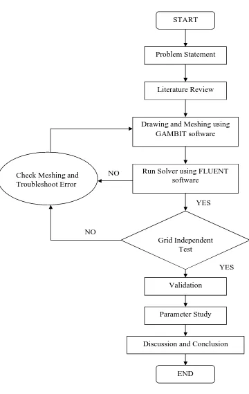
1.1 Flowchart for the Project 7
2.1 Ranges of Channel Diameters Employed in Various Applications 9 3.1 Dimension of 3D minichannel model created in GAMBIT 24 3.2 Face Mesh for Channel Inlet looking from X-direction 26
3.3 Volume Mesh for Entire Minichannel 26
3.4 Geometry and Boundary Condition 27
3.5 FLUENT grid check 29
3.6 Grid Scale 30
3.7 Solver and Viscous Model Define Used 30
3.8 Defining Energy Model 31
3.9 Boundary Condition Inlet Velocity Setting 34 3.10 Boundary Condition Pressure Outlet Setting 34 3.11 Boundary Condition for Bottom Wall Setting 35
3.12 Solution Initialization 36
3.13 Residual Monitor for Iteration Process 37 4.1 Comparison between measured and computed temperature profile at different
location in the channel. 39
4.2 Graph of Compute Temperature versus Channel Position 50 micron from
xiii
NO TITLE PAGE
NOMENCLATURE
A = Area, m²
CFD = Computational Fluid Dynamics
f
C = Coefficient of Friction
h
d = Hydraulic Diameter, m
D = Diameter, m
g = Gravity Acceleration, m/s²
mm = Millimeter, mm
P = Pressure, Pa
Re = Reynolds Number
Recr = Critical Reynolds Number
T = Temperature, ºC
2D = Two-dimensional
3D = Three-dimensional
µm = Micrometer, µm
/ D
= Effective Roughness Ratio
= Density, kg/m³
= Kinematics Viscosity, m²/s = Dynamics Viscosity, N·s/m²
V = Velocity, m/s
= Heat flux Density, W/m² P
xv
LIST OF APPENDICES
NO TITLE PAGE
A Table 2.2: Summary of Enhancement Techniques for Use in 52 Microchannels and Minichannels.
Table 2.3: Summary of Recent Studies Investigation on Evaporation 53 in Minichannel and Microchannel
B Caney, N. & Marty, P. & Bigot, J. (2006). Friction Losses 57 And Heat Transfer of Single-Phase Flow in a Mini-Channel.
Chapter One is focusing on the project background, project objectives, problem statements, scope of work and flow of the project.
1.1 Project Background
Microchannel and minichannel cooling has made the high heat flux removal in such applications as microprocessor cooling, cooling of high power electronic equipment, compact heat exchangers, and even compact fuel cells possible. The small hydraulic diameter increases the heat transfer coefficients in these passages.
2
The majority of researchers working in this field realize the benefits of two phases flow systems to meet the cooling requirements for high heat fluxes. The heat transfer improvement gained by a two-phase system (given the same heat flux and mass flux) is well documented in conventional sized channels, and current research is ongoing in the microchannel region. However, the total pressure drop, pumping requirements and system complexity are greatly increased in a two-phase flow system.
A study of the influence of the experimental uncertainties shows a considerable importance of the precise knowledge of the hydraulic diameter. An inaccurate evaluation of this quantity can lead to a huge error in the friction factor calculation. As the heat flux densities increased in automotive, aerospace, air separation and cryogenic industries, the use of compact evaporators became quite widespread. The plate-fin evaporators are used quite commonly in these applications. Again, looking at their dimensions, the lower limit of about 600 μm(micrometer) may be considered as the boundary of the next range. The channels employing hydraulic diameters between 600 μm and 3 mm (millimeters) are referred to as minichannels.
boiling in channels smaller than 30 to 50 μm requires especially clean fluids. The pumping power requirements are also significantly higher. However, boiling inside such small passages provides a very effective way of fluid movement, as well as relatively large heat dissipation capabilities for specialized applications. To sum up the definitions based on the above discussion, the following ranges of hydraulic diameters can be classified as below:
4
1.2 Project Objectives
This part will discuss deeply about the project objectives. This project is developing with the following objectives:
(a) To computationally simulate laminar flow in rectangular minichannel by using Computational Fluid Dynamics (CFD) software. There are many types of CFD software, but for this project GAMBIT version 2.2 and FLUENT version 6.2 are used.
(b) To study and understand on how to create and meshing geometry in GAMBIT and selecting the right solver to compute in FLUENT and know how to use both software effectively.
(c) To study on how minichannel characteristic and the application in this new microfluid era technologies.
(d) To study the pressure drop and heat transfer along the single phase rectangular minichannel.
needing the cooling of components in a confined space such as minichannel cooling has made the high heat flux removal in such applications as microprocessor cooling, cooling of high power electronic equipment, compact heat exchangers, and even compact fuel cells possible. So, research in this field is very important to know the flow in the channel, heat transfer rate, pressure losses and limitation of minichannel.
Flow in small hydraulic diameter channels is becoming increasingly important in many diverse applications. The previous studies addressing the effects of the channel size on the flow patterns, and heat transfer and pressure drop performance are reviewed.
As the heat flux density in increased in automotive, aerospace, air separation and cryogenic industries, the use of compact evaporators become quite widespread. The plate fin evaporators are used quite commonly in these applications. The application in the field microelectronic created entirely new paradigms. The evolution of ink jet printing technology showed that importance of small dimension passage fluid flow.
6
1.4 Scope of Work
This project will concentrate on simulating laminar flow in rectangular minichannel. This concept and the correct calculation must be known to get the correct value for each parameter that has been studied. The detailed scope for this project is:
(a) The dimension of the channel that has been studied on this project is 1 milimeter x 1 milimeter cross-sectional area and 420 millimeters length. The material used for this minichannel wall is aluminum. The entrance part of minichannel analysis is neglected because this study is focus on investigation of flow characteristic in minichannel.
(b) Reynolds Number is taken from 600 - 1800. This is because to develop fully laminar flow in pipe or minichannel, the value for laminar region must be taken below 2100 approximately. This Reynolds number is used to determine average velocity as the compute inlet velocity for the minichannel.
(c) The heat flux supplied to the fluid is constant at 11 W which is corresponding to a mean heat flux density equal to 6400 W/m² due to the size of the channel.
(d) Three Dimension (3-D) simulation by using three dimension double precision (3DDP) for fluent version selection.
Figure 1.1: Flowchart for the Project START
Problem Statement
Literature Review
Drawing and Meshing using GAMBIT software
Run Solver using FLUENT software
Grid Independent Test
Validation Check Meshing and
Troubleshoot Error
Discussion and Conclusion
END Parameter Study NO
NO
YES