Procedia Engineering 68 ( 2013 ) 647 – 653
1877-7058 © 2013 The Authors. Published by Elsevier Ltd.
Selection and peer-review under responsibility of The Malaysian Tribology Society (MYTRIBOS), Department of Mechanical Engineering, Universiti Malaya, 50603 Kuala Lumpur, Malaysia
doi: 10.1016/j.proeng.2013.12.234
ScienceDirect
The Malaysian International Tribology Conference 2013, MITC2013
Comparison between up-milling and down-milling operations on
tool wear in milling Inconel 718
M. A. Hadi
a, J.A. Ghani
a*, C.H. Che Haron
a, M. S. Kasim
baDepartment of Mechanical & Materials Engineering, Faculty of Engineering and Built Environment, Universiti Kebangsaan Malaysia, 43600 Bangi, Selangor, Malaysia
bFaculty of Manufacturing Engineering, Universiti Teknikal Malaysia Melaka, Hang Tuah Jaya, 76100 Durian Tunggal, Melaka, Malaysia
Abstract
The demand for the use of nickel-based superalloy such as Inconel 718 is increasing in aerospace industry as it is efficient for energy and has excellent properties. In this paper, the experimental studies of tool wear mechanism and tool life in ball nose end milling of Inconel 718 is presented under minimum quantity lubricant (MQL) condition. The evaluations of the results are focusing on the comparison of up-milling and down-milling operations using physical vapor deposition (PVD) - coated carbide inserts. Machining parameters; depth of cut, feed rate and cutting speed are considered during the evaluation. The experimental results showed that down-milling operation has better results in terms of tool wear than up-milling operation. Chipping on cutting tool edge was the primary reason that responsible to notch wear with prolong machining.
© 2013 The Authors. Published by Elsevier Ltd.
Selection and peer-review under responsibility of The Malaysian Tribology Society (MYTRIBOS), Department of Mechanical Engineering, Universiti Malaya, 50603 Kuala Lumpur, Malaysia.
Keywords: Inconel 718; Ball nose end milling; Up-milling; Down-milling; Chipping; Notch wear
Nomenclature
BUE build-up-edge DOC depth of cut (mm)
MQL minimum quantity lubricant fz feed rate (mm/tooth) v speed (m/min)
Vbmax maximum flank wear
*Corresponding author. Tel.: +603 8921 6505; fax: +603 8925 9659.
E-mail address: [email protected] (J.A. Ghani)
© 2013 The Authors. Published by Elsevier Ltd.
1.Introduction
Inconel 718 is a group of nickel based superalloys which is widely employed in the aerospace industry due to their high-temperature strength, its superior creep and high corrosion resistance. However, Inconel 718 is also well known as a difficult-to-machine material and this cause disadvantages properties during machining process such as poor thermal conductivity, contained high chemical affinity with almost all tools, high strength due to their high-temperature properties and its work harden rapidly [1]. In addition, these properties will lead to severe tool injury, high stress and temperature buildup on the tool face, warping in small parts and rapidly tool wear which resulting shorter tool life [2]. In most cases, the problem encountered during machining Inconel 718 is due to temperature generated which cause tool damage even at low cutting speed and low feed rate [3, 4]. On the other hand, chips are easy to weld on the tool face to form BUE which directly result severe surface damages extending to subsurface levels [3].
Nowadays, the increasing demands for higher quality in machining and manufacturing efficiency have leaded the researchers to put every effort to develop the efficient and the best method to machine Inconel 718. Li et al. [2] investigated the tool wear propagation and the cutting force variations in the end milling operation. They have found that significant flank wear was the predominant failure mode affecting the tool life and tool wear was the major reason for the gradual increase of the mean peak force in successive cutting passes. Kasim et al.[5] reported that in ball nose end milling, the predominant tool failure for the four round cutting tools are notch wear and flaking near the depth of cut zone where they cause by the repetitive cyclic load. They also claimed that large radial of depth is the main factor affecting the tool wear. Harshad and Suhas [6] have studied the effect of machining parameters on the quality of surface obtained in a single-pass of ball-end milling cutter. They also reported that maximum surface roughness is measured near the tool tip region on the machined surface, where the minimum surface roughness is obtained in the stable cutting zone. For further investigation on the tool wear, Krain et al. [7] have done two phases of experiments to observe the effect of various cutting parameters and also different tool materials and tool geometries; abrasion, adhesion and attrition are the main tool wear mechanisms and BUE is formed when the pressure and chemical affinity are high. The same finding is obtained by Khan et al. [8] through their results on finish turning of Inconel 718, where abrasion is the main cause that triggers the dominant wear mode, while workpiece material adhesion is similarly prominent and BUE formation is observed at every parameter level.
In the case of milling, it is also known as an interrupted cutting process where the direction of the cutting force is changing due to the tool rotation, and as the tooth enters and leaves the workpiece for every cutting pass [5,9]. This nature resulted in various wear mechanism, cutting temperature and dynamic stability compared to the continuous cutting process. Research carried out by Bouzakis et al. [10] has shown that the kinematics of milling process (up-milling or down-(up-milling), have significantly affects the stress distribution during the material removal and also the cutting performance. The results obtained through an experimental study done by Li et al. [2], shown that the tool flank wear propagation in the up milling operation is more rapid than that in the down milling operations.
All these studies explained more insight of tool performance in down milling operation of Inconel 718. However, the correlation between cutting performance and kinematics orientation of difficult-to-machine material like Inconel 718 has rarely been studied. The purpose of this paper is to study more comprehensively the tribological behaviours of ball nose end milling in different kinematics direction (up and down) of Inconel 718 with PVD coated TiAlN carbide. Specifically, the wear and tool life are measured in order to assess the effects of up-milling or down-milling on wear mechanism generated.
2.Methodology
2.1.Workpiece material and cutting tool
Table 1. Nominal chemical composition of Inconel 718
Elements Al B C Nb.Ta Co Cr Cu Fe Mn Mo Ni P S Si Ti
% wt. 0.49 0.004 0.051 5.05 0.3 18.3 0.04 18.7 0.23 3.05 53 <0.005 <0.002 0.08 1.05
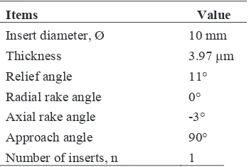
The cutting tool used in machining test was a Sumitomo ball nose type milling cutter with a nominal diameter of 16 mm attached to a BIG Hi-Power Milling Chuck DV40-HMC20-85 for powerful and precise clamping, and the overhang length was 60 mm. The insert was tungsten carbide with multi-layer PVD TiAlN/AlCrN grade ACK 300. The used cutting tool and tool holder specification are shown in Table 2.
Table 2. Cutting tool geometry
Items Value
Insert diameter, Ø 10 mm Thickness 3.97 ȝm Relief angle 11° Radial rake angle 0° Axial rake angle -3° Approach angle 90° Number of inserts, n 1
2.2.Tool wear measurement and experiment parameters
The tribological behavior of Inconel 718 in term of wear during up-milling and down-milling has been investigated. The milling process was interrupted at the specific cutting interval to study the growth of the tool wear for every level of parameter. The tool wear of the insert was observed using a Mitutoyo toolmaker’s microscope with 30x magnification and ±0.003 mm repeatability. After the wear observation and measurement, the insert was used again for the next milling experiment. The experiment was repeated until the tool failure occurred, where this should meet one of the ISO-8688 criteria, which are: (i) uniform flank wear of 0.3 mm; (ii) maximum flank wear is 0.5 mm; or (iii) when excessive flanking or fracture happened [11].
For up-milling operation, the tool wear measurement was taken after a single pass of every experiment since in some runs the inserts have already worn out after the first pass. For down-milling operation, the wear data was taken until the twentieth runs for each parameter. The comparison of the tool life was made on the longest time taken during down-milling operation.
For up-milling and down-milling, the cutting parameters were set into three variables which were cutting speed, feed rate and depth of cut. MQL was used as a coolant throughout the experiment with fixed flow rate at 50 ml/h. The details of the machining parameters are provided in Table 3 below.
Table 3. Machining parameters used during the experiment
Cutting parameters Unit Values
Cutting speed, v m/min 100, 120, 140 Feed rate, fz mm/tooth 0.1, 0.15, 0.2
3.Results and discussion
3.1.Tool wear in up- milling process
In up-milling process, the cutter tends to scoop the metal start from the bottom and goes all the way upwards. In other words, the width of chip will starts from zero and increases. As the cutter encounters minimum chip thickness when it start entering the workpiece, rubbing at the beginning of the cut will cause an excessively work hardened layer in the workpiece and this condition will generate lower temperature around the cutting edge and chip surface as compared to down milling due to less friction interface between the tool and the chip [12].
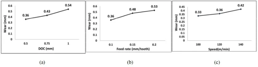
Fig. 1(a) (b) and (c) show the effect of cutting parameters on the flank wear. The effect of DOC on tool wear by keeping feed rate and speed constant is shown in Fig.1(a). From Fig. 1(a), it is clearly shown that DOC is directly proportional to the tool wear. In single cutting pass measurement, the tool wear increases as the DOC increases. The same finding was obtained by Ali and Salama [13] through their experiment on austenitic stainless steel where they found that as the DOC increases, chip width will also increases and the center of pressure of the chip tend to moves away from the cutting edge, which initiated the crack to occur. At DOC 1 mm, the tool wear meet the maximum flank wear (Vbmax) which is 0.5 mm as per ISO-8688 in only one pass.
Fig. 1(b) indicates the effect of feed rate on the tool wear by keeping the DOC and speed constant. From the result obtained, feed rate also give a direct proportional relation to the tool wear, where increasing the feed rate will accelerate the tool wear. For feed rate of 0.2 mm/tooth, tool is already worn-out in a single cutting pass with the wear reading of 0.53 mm. This phenomenon is due to BUE formed on flank face that changes the geometry of the tool [14]. The result as in Fig. 2(a) was obtained from the experiment and it shows BUE occurred near the DOC line because of higher stress acting on the cutting edge.
Fig. 1. Maximum wear in single cutting pass when (a)DOC are set at 0.5, 0.75 and 1 mm while feed rate and speed are constant at 0.1 mm/tooth and 120 m/min, (b) feed rate are set at 0.1, 0.15 and 0.2 mm/ tooth while DOC and speed are constant at 0.5 mm and 120 m/min, (c) speed are set
at 100, 120 and 140 m/min while DOC and feed rate are constant at 0.5 mm and 0.1 mm/tooth.
From Fig. 1(c), the effect of cutting speed is clearly shown that the flank wear is increased with increase of cutting speed. The experiment was done with a constant DOC; 0.5 mm and feed rate; 0.1 mm/tooth. The result also concluded that as the cutting speed is increased, abrasive and adherence of workpiece on the flank face can be clearly seen as illustrated in Fig. 2(b). In general, this phenomenon is mainly due to the generation of high contact pressure and temperature between workpiece and tool, where most of the wear mechanism of carbide tool is abrasive and adhesive wear [14]. In term of chip morphology, up-milling operation tends to generate a segmented chip with a typical saw-tooth shape as shown in Fig. 2(c). This phenomenon showed that the local rate of heat build-up in the material is large enough that thermal softening overwhelms the effect of strain hardening. The segmented chip will result an increase in tool wear and degradation of workpiece surface finish [15].
Abrasion
Fig. 2 (a) BUE (b) Abrasive and adhesive wear (c) Segmented chip with typical saw-tooth shape.
3.2.Tool wear in down-milling operation
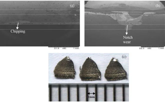
As compared to up-milling operation, down-milling process will tend to scoop the metal starting at the top of DOC and goes all the way to the bottom. In this method, chips are generally bigger (approximate two times bigger than up-milling) because of the high force during contact and it can produce a better surface finish as compared to up-milling operation. However, the high impact force can cause chipping (Fig. 3a) due to the harden layer on the surface and this will promoting the formation of notch wear (Fig. 3b). Localized of notch wear can lead to tool fracture and will be considered as a catastrophic failure. Besides that, the chip morphology during down-milling was also different than with up-milling. Whereby, in down-milling the chip produced was a discontinuous serrated chip as shown in Fig. 3(c). This type of chip will reduce the tool wear and produce better quality of workpiece surface finish.
Fig. 3. Tool wear patterns observed (a) Chipping (b) Notch wear (c) Discontinuous serrated chip.
Notch wear
(a) (b)
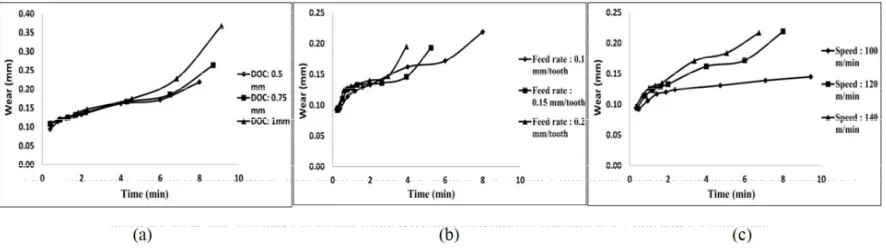
The difference in cutting results during down-milling that due to change of DOC, feed rate and speed over cutting time can be seen in Fig. 4(a), (b) and (c). Overall, all the parameters show the improvements in tool wear when the same parameters used in up-milling are applied in down-milling operation. From the results in Fig. 4(a), the progress of flank wear increases steadily at the initial stage before unevenly progressed after around four minutes of cutting times. This is due to chipping and further more will lead to notch wear that caused by the repetitive load [5].
The effect of feed rate during down-milling is observed in Fig. 4(b). In general, the progress of the wear has three stages: initial, steady-state and worn-out regions. All the feed rate values started with the increasing of flank wear until they reached almost 1 minute before they gone through steady state region for a certain period of time. For fz= 0.2 mm/tooth, it takes 3 minutes, while for fz= 0.15 mm/tooth and fz= 0.1 mm/tooth both respectively take 4
minutes and 8 minutes before the wear drastically increase, leaving the steady state region. As in up-milling, flank wear increases when the feed rate is increased due to BUE formed at flank face and increase the normal contact stress at the tool-chip interface and in the tool-chip contact area. The chipping of the cutting edge will take place and leads to tool breakage when the level of normal contact stress reaches the breaking feed of the tool [16].
Fig. 4. Maximum wear in twenties cutting pass when (a)DOC are set at 0.5, 0.75 and 1 mm while feed rate and speed are constant at 0.1 mm/tooth and 120 m/min, (b) feed rate are set at 0.1, 0.15 and 0.2 mm/ tooth while DOC and speed are constant at 0.5 mm and 120 m/min, (c)
speed are set at 100, 120 and 140 m/min while DOC and feed rate are constant at 0.5 mm and 0.1 mm/tooth.
Fig. 4(c) shows the influence of different cutting speed on tool wear under down-milling operation. It can be observed that tool wear is very sensitive to cutting speed. When the speed is low (100 m/min), the tool wear on the flank face is slowly increasing compared to the progress of wear during high speed (140 m/min). This was most likely due to increase of the cutting temperature which resulted in a loss of material strength and increase of its plasticity [17]. In other words, tool tips become easier to get wear where abrasive wear marks and workpiece material adhesion were still prevalent in all test performed.
4.Conclusions
The article presents the findings of the experiments during up-milling and down-milling on the effect of DOC, feed rate and cutting speed to the tool wear in ball nose end milling of Inconel 718. In general, tool wear is increased with increased DOC, feed rate and cutting speed. It was found that the tool flank wear propagation in the up-milling operation was more rapid compared to down-milling operation. The results also showed that significant pitting and notch wear were the predominant failure mode typically located near the DOC line that affecting tool performance and tool life. All three components have the contributions on notch wear failure where DOC and feed rate affects the volume of material and the cutting speed affect the cutting temperature. In the other hand, the chip morphology is different in both operations, where up-milling operation produced a segmented chip with typical saw-tooth shape and down-milling operation produced a discontinuous serrated chip.
Acknowledgements
References
[1] Dudzinski, D., Devillez, A., Moufki, A., Larrouquère, D., Zerrouki, V., Vigneau, J., 2004. A review of developments towards dry and high speed machining of Inconel 718 alloy. International Journal of Machine Tools and Manufacture 44(4), p. 439–456.
[2] Li, H. Z., Zeng, H., Chen, X. Q., 2006. An experimental study of tool wear and cutting force variation in the end milling of Inconel 718 with coated carbide inserts. Journal of Materials Processing Technology 180(1-3), p. 296–304.
[3] Liao, Y. S., Lin, H. M., Wang, J. H., 2008. Behaviors of end milling Inconel 718 superalloy by cemented carbide tools, Journal of Materials Processing Technology 201(1-3), p. 460–465.
[4] Zhang, S., Li, J. F., Wang, Y. W., 2012. Tool life and cutting forces in end milling Inconel 718 under dry and minimum quantity cooling lubrication cutting conditions, Journal of Cleaner Production 32,p. 81–87.
[5] Kasim, M. S., Che Haron, C. H., Ghani, J. a., Sulaiman, M. A., Yazid, M. Z. A., 2013. Wear mechanism and notch wear location prediction model in ball nose end milling of Inconel 718, Wear, In press.
[6] Harshad, A. S., Suhas, S. J., 2012. Analysis of machined surface quality in a single-pass of ball-end milling on Inconel 718, Journal of Manufacturing Processes 14(3), p.257–268.
[7] Krain, H. R., Sharman, a. R. C., Ridgway, K., 2007. Optimisation of tool life and productivity when end milling Inconel 718TM, Journal of Materials Processing Technology 189(1-3), p. 153–161.
[8] Khan, S. A., Soo, S. L., Aspinwall, D. K., Sage, C., Harden, P., Fleming, M., White, A., Saoubi, R. M., 2012. Tool wear/life evaluation when finish turning Inconel 718 using PCBN tooling, Procedia CIRP 1(5), p. 283–288.
[9] Bayly, P. V, Insperger, T., Mann, B. P., Ste, G., 2003. Stability of up-milling and down-milling, part 1: alternative analytical methods ´. International Journal of Machine Tools & Manufacture 43,p. 25–34.
[10] Bouzakis, K.-D., Gerardis, S., Katirtzoglou, G., Makrimallakis, S., Michailidis, N., Lili, E., 2008. Increasing tool life by adjusting the milling cutting conditions according to PVD films’ properties. CIRP Annals - Manufacturing Technology 57(1), p. 105–108. [11] ISO8688-2, Tool Life Testing in Milling - Part 2 : End Milling, International Organization for Standardization, Geneva, 1989. [12] Toh, C. K., 2005. Comparison of chip surface temperature between up and down milling orientations in high speed rough milling of
hardened steel. Journal of Materials Processing Technology 167(1), p. 110–118.
[13] Ali Khan, A., Salama Hajjaj, S. (2006). Capabilities of Cermets Tools for High Speed Machining of Austenitic Stainless Steel.pdf. Journal of Applied Sciences 6(4), p. 779–784.
[14] Seeman, M., Ganesan, G., Karthikeyan, R., Velayudham, A., 2010. Study on tool wear and surface roughness in machining of particulate aluminum metal matrix composite-response surface methodology approach, The International Journal of Advanced Manufacturing Technology 48, p. 613–624.
[15] Komanduri, R., Schroeder, T., Hazra, J., Von Turkovich, B. F., & Flom, D. G., 1982. On the catastrophic shear instability in high-speed machining of an AISI 4340 steel. J. Eng. Ind.(Trans. ASME) 104(2), p. 121-131.
[16] Astakhov, V. P., 2006. Effects of the cutting feed, depth of cut, and workpiece (bore) diameter on the tool wear rate, The International Journal of Advanced Manufacturing Technology, 34(7-8), 631–640.