DEVELOPMENT OF LIGHTWEIGHT POROUS CONCRETE AS WALL INSULATION
NURULHILMI ZAIEDAH BINTI NASIR
This report as a to fully my bachelor in Mechanical Engineering Structure and Materials
Faculty of Mechanical Engineering University Technical of Malaysia Melaka
SUPERVISOR DECLARATION
“I hereby declare that I have read this thesis and in my opinion this report is sufficient in terms of scope and quality for the award of the degree of
Bachelor of Mechanical Engineering (Structure and Materials)”
Signature : ... Supervisor : DR. HADY EFENDY Date : ...
Signature : ...
DECLARATION
“I hereby declare that the work in this report is my own except for summaries and quotations which have been duly acknowledged.”
Signature : ...
DEDICATION
For my beloved father and mother, Dearest family members,
ACKNOWLEGEMENT
Assalammualaikum and Salam Satu Malaysia,
Thanks to Allah, for giving me permission to complete this project. I would like to witness my graceful thanks to all for the support, encouragement and inspirations that I have received during completing this project.
First and foremost, I would like to thank my supervisor of this project, Dr. Hady Efendy for the valuable guidance and advice. He inspired me greatly in doing this project. His willingness to motivate me contributed tremendously to my project. I also would like to thank his for showing me some example that related to the topic of my project.
Besides, I would like to thank the authority of University Teknikal Malaysia Melaka (UTeM) for providing me with a good environment and facilities to complete this project. Also, I would like to take this opportunity to thank to the Faculty of Mechanical Engineering (FKM) of Universiti Teknikal Malaysia Melaka (UTeM) which have provide me valuable information as the guidance of my project. Especially, Mr. Mahathir as our Technician at Sains Bahan Lab.
ABSTRACT
ABSTRAK
CONTENTS
TITLE PAGE
DECLARATION ii
DEDICATION iii
ACKNOWLEGMENT iv
ABSTRACT v
ABSTRAK vi
TABLES OF CONTENTS vii
LIST OF FIGURES ix
LIST OF TABLES xi
CHAPTER 1 INTRODUCTION
1.1 Background Research 1
1.2 Objectives 2
1.3 Problem Statement 2
1.4 Research Scope 3
1.5 Research Methodology 3
CHAPTER 2 LITERATURE REVIEW
2.1 Concrete 4
2.2 Types of Concrete 5
2.2.1 Porous Concrete 5
2.2.2 Polymer Concrete 7
2.3 Insulation Material 8
2.4 Cement 10
2.5 Aggregates 11
2.5.1 Lightweight Aggregates 11
2.5.2 Fine Aggregates 12
2.6 Lime (Calcium Carbonate) 13
2.7 Gypsum 13
2.8 Water 14
CHAPTER 3 METHODOLOGY
3.1 Material 16
3.2 Flowchart 17
3.3 Raw Material 18
3.4 Material Preparation 18
3.5 Testing Standard 19
3.6 Testing Standard 19
3.6.1 ASTM C39 Press Test 19
3.6.2 ASTM C380-79 Porosity and Density Test 22
3.7 Optical Microscope 23
CHAPTER 4 RESULTS
4.1 Physical Properties 25
4.1.1 Density Testing 25
4.1.2 Porosity Testing 33
4.2 Mechanical Properties / Compressive Testing 38 4.3 Macro and Microstructure Analysis 47
CHAPTER 5 DISCUSSION
5.1 Physical Properties / Density and Porosity 53 5.2 Mechanical Properties / Compressive
56
5.3 Macro and Microstructure 59
CHAPTER 6 CONCLUSION AND RECOMMENDATION
6.1 Conclusion 60
6.2 Recommendation 61
REFERENCES 62
LIST OF FIGURES
NO TITLE PAGE
2.1 Concrete 4
2.2 Porous Concrete 6
2.3 Polymer Concrete 7
2.4 Insulation Material 8
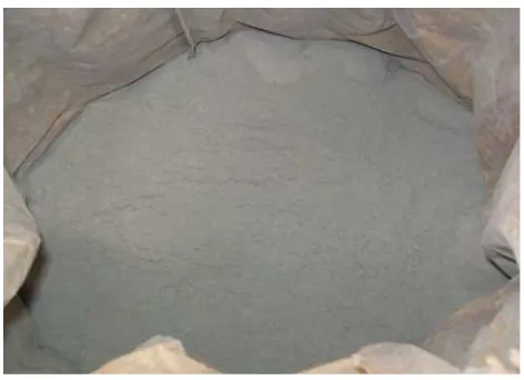
2.5 Cement 10
2.6 Aggregates 11
2.7 Fine Aggregates 12
2.8 Lime (Calcium Carbonate) 13
2.9 Gypsum 14
2.10 Polyurethane 15
3.1 Flowchart Process 17
3.2 Compressive Test 20
3.3 Compressive Test Machine 21
3.4 Optical Microscope 24
4.1 Graph Density vs %Lime for 500 gram of sand 27
4.2 Graph Density vs %PU for 500 gram of sand 27
4.3 Graph Density vs %Lime for 550 gram of sand 29
4.4 Graph Density vs %PU for 550 gram of sand 30
4.5 Graph Density vs %Lime for 600 gram of sand 32
4.6 Graph Density vs %PU for 600 gram of sand 32
4.7 Graph Porosity vs %Lime for 500 gram of sand 33
4.8 Graph Porosity vs %PU for 500 gram of sand 34
4.9 Graph Porosity vs %Lime for 550 gram of sand 35
4.10 Graph Porosity vs %PU for 550 gram of sand 35
4.11 Graph Porosity vs %Lime for 600 gram of sand 36
4.13 Specimen A1 38
4.14 Specimen A2 38
4.15 Specimen A3 39
4.16 Graph Compressive vs %PU for 500 gram of sand 40
4.17 Graph Compressive vs %Lime for 500 gram of sand 40
4.18 Specimen B1 41
4.19 Specimen B2 41
4.20 Specimen B3 42
4.21 Graph Compressive vs %PU for 550 gram of sand 43
4.22 Graph Compressive vs %Lime for 550 gram of sand 43
4.23 Specimen C1 44
4.24 Specimen C2 44
4.25 Specimen C3 45
4.26 Graph Compressive vs %PU for 600 gram of sand 46
4.27 Graph Compressive vs %Lime for 600 gram of sand 46
4.28 Microstructure of Sample A1 47
4.29 Microstructure of Sample A2 47
4.30 Microstructure of Sample A3 47
4.31 Microstructure of Sample B1 48
4.32 Microstructure of Sample B2 48
4.33 Microstructure of Sample B3 48
4.34 Microstructure of Sample C1 49
4.35 Microstructure of Sample C2 49
4.36 Microstructure of Sample C3 49
4.37 %5 PU for specimen A1, B1 and C1 50
4.38 %3 PU for specimen A2, B2 and C2 50
4.39 %1 PU for specimen A3, B3 and C3 50
5.1 Comparison Density, Porosity vs %PU for 500 gram sand 52 5.2 Comparison Density, Porosity vs %PU for 550 gram sand 52 5.3 Comparison Density, Porosity vs %PU for 600 gram sand 53 5.4 Graph Density vs %Lime for 500, 550, and 600 gram sand 54 5.5 Graph Porosity vs %Lime for 500, 550, and 600 gram sand 55 5.6 Graph Compressive vs %PU for 550, 550 and 600 gram sand 57 5.7 Graph Compressive vs %Lime for 500,550, and 600 gram sand 58
LIST OF TABLES
NO TITLE PAGE
3.1 Raw Material Composition 18
4.1 Composition Porous Concrete Sample A 25
4.2 Sample Code A1 26
4.3 Sample Code A2 26
4.4 Sample Code A3 26
4.5 Result Sample A 26
4.6 Composition Porous Concrete Sample B 28
4.7 Sample Code B1 28
4.8 Sample Code B2 28
4.9 Sample Code B3 28
4.10 Result Sample B 28
4.11 Composition Porous Concrete Sample C 30
4.12 Sample Code C1 30
4.13 Sample Code C2 31
4.14 Sample Code C3 31
4.15 Result Sample C 31
4.16 Porosity Sample A 33
4.17 Porosity Sample B 34
4.18 Porosity Sample C 36
4.19 Data Compressive Test A1 38
4.20 Data Compressive Test A2 39
4.21 Data Compressive Test A3 39
4.22 Data Compressive Test B1 41
4.23 Data Compressive Test B2 42
4.24 Data Compressive Test B3 43
4.26 Data Compressive Test C2 45
4.27 Data Compressive Test C3 45
5.1 Data Testing and Porosity Testing 51
1
CHAPTER 1
INTRODUCTION
1.1 Background Research
Concrete is a material that widely used as building components. Concrete has
a great strength as a construction material and it is easy to change into other materials
accordance with needs. One of the uses of concrete is as partition wall where the
design of concrete must be lightweight and have a good strength. The most common
concrete that have being use as a partition wall is porous concrete.
Population growth led to high demand in housing and office buildings from
years to years. One of the most crucial components in building structures is the
partition wall because it needs to be good in its acoustic properties and have high
strength. In order to obtain a good acoustic property, it is suggested to use the porous
building materials which are good in absorbing sound waves.
In manufacturing of concrete block, blowing agents is required to produce
pores in concrete. The most common blowing agent that being used is a aluminum
powder or polyurethane. In addition, the necessary material that can be also making
the concrete is expanding by adding gypsum. One of the advantages of the existence
pores in the concrete causing the concrete to be mild.
Lightweight nature of these provide several advantages, including providing
convenience in the process and can reduce damage to buildings experienced the
2
earthquake. To reduce the damage caused by earthquake, then the required
earthquake resistant structures.
1.2 Objectives
The aim of this final year project
is:-• To development of alternative insulation material for wall insulation obtain the physical properties and mechanical properties.
• To manufacturing of lightweight porous concrete materials. • To study the characteristic lightweight porous concrete products.
1.3 Problem statement
The use of concrete for insulating materials in building construction causes
some problem such as having a high weight or relatively heavy. Concrete also has
pocket and vein into which water can seep and cause damage to wall and floors. It is
also cannot reflect the sound well. When the sound reaches to the concrete wall, it
will be reflect the big wave signal to people surrounding.
Compared with the porous concrete, it has a porous that will be reduced the
sound reflection. Porous concrete also available in many parts of the world and can
be used in producing in wide range of units and suitable strength values for different
fields of application such as internal and external wall, inner leaves of external cavity
3
1.4 Research scope
The scope for this final project is limited to the problem of fabrication and
characterization of lightweight porous concrete as follows.
1. Research conducted at the Laboratory of Material Science UTeM.
2. Material that being are use gypsum, sand, aluminum powder/Polyurethane,
water and Portland cement.
3. Analysis on the mechanical properties of porous concrete with various
compositions that include compressive strength.
4. Analysis on the testing physical properties includes density and porosity
testing.
5. In this study, researcher decides to add aluminum powder or polyurethane as
a method in reducing the density of lightweight porous concrete.
1.5 Research methodology
Concrete is a material that widely used as building components. Concrete has
a great strength as a construction material and it is easy to change into other materials
accordance with needs. One of the uses of concrete is as partition wall where the
design of concrete must be lightweight and have good strength. The most common
concrete that have being use as a partition wall is porous concrete.
This study includes analysis of physical properties such as density and
porosity while the analysis of mechanical properties such as compressive strength.
4
CHAPTER 2
LITERATURE REVIEW
2.1 Concrete
Concrete is a material used in building construction, consisting of a hard,
chemically inert particulate substance, known as an aggregate (usually made from
[image:17.595.214.428.419.574.2]different types of sand and gravel), that is bonded together by cement and water.
Figure 2.1: Concrete
The Assyrians and Babylonians used clay as the bonding substance or
cement. The Egyptians used lime and gypsum cement. In 1756, British engineer,
John Smeaton made the first modern concrete (hydraulic cement) by adding pebbles
as a coarse aggregate and mixing powered brick into the cement. In 1824, English
inventor, Joseph Aspdin invented Portland cement, which has remained the dominant
cement used in concrete production. Joseph Aspdin created the first true artificial
5
the chemical properties of the materials and Joseph Aspdin created stronger cement
than what using plain crushed limestone would produce.
The other major part of concrete besides the cement is the aggregate.
Aggregates include sand, crushed stone, gravel, slag, ashes, burned shale, and burned
clay. Fine aggregate (fine refers to the size of aggregate) is used in making concrete
slabs and smooth surfaces. Coarse aggregate is used for massive structures or
sections of cement.
Concrete that includes imbedded metal (usually steel) is called reinforced
concrete or ferroconcrete. Reinforced concrete was invented (1849) by Joseph
Monier, who received a patent in 1867. Joseph Monier was a Parisian gardener who
made garden pots and tubs of concrete reinforced with an iron mesh. Reinforced
concrete combines the tensile or bendable strength of metal and the compression
strength of concrete to withstand heavy loads. Joseph Monier exhibited his invention
at the Paris Exposition of 1867. Besides his pots and tubs, Joseph Monier promoted
reinforced concrete for use in railway ties, pipes, floors, arches, and bridges.
2.2 Types of Concrete
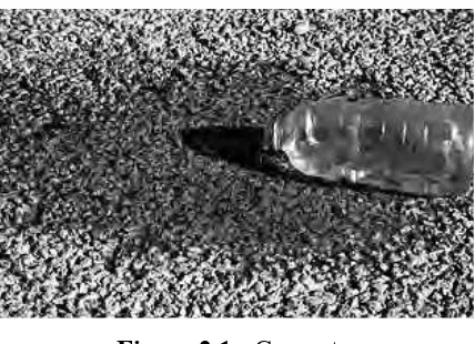
2.2.1 Porous Concrete
Porous concrete (also referred to as enhanced porosity concrete, porous
concrete, Portland cement pervious pavement and pervious pavement) is a subset of a
broader family of pervious pavements including porous asphalt, and various kinds of
grids and paver systems. Porous concrete is thought to have a greater ability than
porous asphalt to maintain its porosity in hot weather and thus is provided as a
6
Figure 2.2: Porous Concrete
Although, porous concrete has seen growing use in Georgia, there is still very
limited practical experience with this measure. According to the U.S. EPA, porous
pavement sites have had a high failure rate – approximately 75 percent. Failure has
been attributed to poor design, inadequate construction techniques, and soils with
low permeability, heavy vehicular traffic and poor maintenance. This measure, if
used, should be carefully monitored over the life of the development.
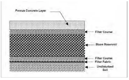
Porous concrete consists of a specially formulated mixture of Portland
cement, uniform, open graded course aggregate, and water. The concrete layer has a
high permeability often many times that of the underlying permeable soil layer, and
allows rapid percolation of rainwater through the surface and into the layers beneath.
The void space in porous concrete is in the 15% to 22% range compared to three to
five percent for conventional pavements. The permeable surface is placed over a
layer of open-graded gravel and crushed stone. The void spaces in the stone act as a
storage reservoir for runoff.
Porous concrete is designed primarily for storm water quality, i.e. the removal
of storm water pollutants. However, they can provide limited runoff quantity control,
particularly for smaller storm events. For some smaller sites, trenches can be
designed to capture and infiltrate the channel protection volume (Cpv) in addition to
WQv. Porous concrete pavement has been used for over 30 years in England and the
US. The interest and researching porous concrete has been generated worldwide
7
Although fundamental information including the influence of the void
ratio/C, cement paste characteristic, volume ratio of coarse aggregate, size of coarse
aggregate and strength of porous concrete have been studied, the optimum condition
to produce good porous concrete has not been established. The mix design, method
of mixing and compaction to produce porous concrete with potentially highest
strength and durability at designed void ratio are still needed. This is mainly due to
the fact that porous concrete is a special concrete with different mix design and
compaction allowing continuous voids to be formed with relatively good
compressive strength.
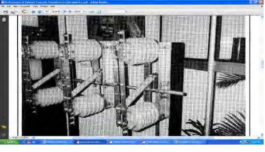
2.2.2 Polymer Concrete
Polymer concrete is a composite material. It consists of a mixture of graded
aggregates and fine fillers bound together by an organic resin system. It is essentially
a highly-filled thermoset material. Low-viscosity organic resins are used and the
processing occurs at room temperature. Polymer concrete is not a “concrete”. That is,
there is hydraulic cement such as neither Portland cement nor water in it. The word
[image:20.595.184.455.485.641.2]concrete” is used only in an etymological sense (Gunasekaran, 1977).
Figure 2.3: Polymer Concrete (Insulator)
Polymer concrete is a highly-filled material. Typically, polymer concrete
formulations contain significantly less organic materials than one encounters in
8
exceed 15% by weight of the composite and there are applications with as little as
3%.
For many civil engineering applications, polymer concrete is mixed very
much like ordinary concrete. In commercial practice, both simple batch mixing
systems and specially-built, micro-processor controlled, continuous output machines
are used. Field placement of polymer concrete is very much akin to that of
conventional concrete with added precautions taken for the safe handling of the
composite material.
In precast product applications, the polymer concrete in molds or forms is
vibrated into place and compacted adequately on vibrating tables. The frequency and
amplitude of the vibration have to be carefully selected depending on the nature of
the mix, the complexity of the molds and their size, the mold material and the
minimum thickness of the polymer concrete material in any particular section. For
most non-dielectric applications, polymer concrete is rarely vacuum treated to
eliminate entrapped air.
2.3 Insulation Material
Thermal insulations are materials or combinations of materials that are used
primarily to provide resistance to heat flow. One feature shared by all insulating
materials used in building applications is their low thermal conductivity l, usually
lower than 0.1 W/m K (Y.A. Cengal, 1998). Since insulating materials act as barriers
on the path of the flow it is obvious that insulation plays an important role in energy
saving. Thus, substantial cost savings can be achieved by correctly insulating
[image:21.595.247.353.638.724.2]buildings.
9
The first time a building was insulated was in USA in 1880 when builders
installed mineral wool in houses. From the 70s new and more effective insulation
materials have been discovered (Y.A. Cengal, 1998). Today, in the European market
inorganic fibrous materials, glass wool and stone wool account for 60% of the
insulation materials, and, organic foamy materials, expanded and extruded
polystyrene and to a lesser extent polyurethane accounts for some 27%
(EURIMA, 2006). In Spain the three most common insulation materials used in
buildings are polyurethane, mineral wool and polystyrene.
At present many types of hollow concrete blocks are manufactured, but with
little attention to the thermal resistance of the units. Two types of standard blocks are
manufactured in the Sultanate of Oman for the construction of single skin masonry
walls and partitions (Pierzchlewicz, 1995). External walls constructed from these
blocks are characterized by high thermal conductivity in which the temperature
within buildings without cooling is very high especially in the summer.
However, in order to reduce the energy consumption during summer, cavity
and double skin walls should be used. Construction of cavity walls requires the
erection of two thin walls separated by an air-gap and braced with metal ties. For
durability considerations, ties are made of stainless steel, which increases the cost.
Double skin walls are similar to cavity walls but polystyrene or a thermal insulation
board is inserted between the two walls, which fills the air-gap.
The introduction of the air-gap or the thermal board reduces the heat transfer
through the wall which improves the thermal resistance of the wall (Pamela, 1969).
Despite the fact that these walls possess lower thermal insulation characteristics than
single skin walls, they are costly and more labor and time consuming. However, due
to the method of construction of cavity walls, many thermal bridges are introduced
(Ahmad et al). The thermal bridges in external cavity walls will render the thermal
resistance of the whole enclosure much lower than that assigned for the cavity wall
itself, because much more heat flows through thermal bridges than through the cavity
10
Thermal performance of fibrous insulations that are widely used in
construction all over the world has been studied numerically by a large number of
researchers. Several researchers studied different heat transfer mechanisms (J.D
Vershoor et al).Other studies have focused on heat transfer modeling (B.K
Larkin et al). There are also specific studies focused on obtaining approximate
expressions for thermal conductivity (B.G. Rennex et al), and thermal diffusivity
(J.V. Beck, 1966). Ucar and Figen (A. Ucar, 2009) determined numerically the
optimum insulation thickness of the external wall for four cities from different
climate zones in Turkey. Typical insulations used in buildings in Turkey were studied
(Foamboard 3500, Foamboard 1500, extruded polystyrene and fiberglass)
2.4 Cement
Cement is a binder, a substance that sets and hardens independently, and can
bind other materials together. Cement used in construction is characterized as
hydraulic or non-hydraulic. Hydraulic cement (Portland cement) hardens because of
hydration chemical reactions that occur independently of the admixture’s water
content; they can harden even underwater or when constantly exposed to wet
weather. The chemical reaction that results when the anhydrous cement powder is
[image:23.595.201.437.523.694.2]mixed with water produces hydrates that are not water-soluble.
11
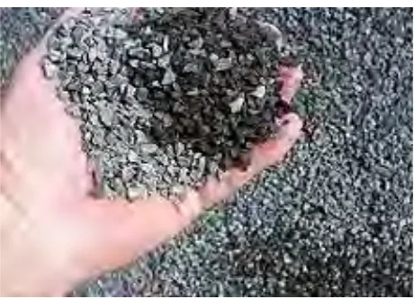
2.5 Aggregates
Aggregates generally constitute about 70–80% by volume of Portland cement
concrete. Due to the large volume fraction it occupies in concrete, aggregates exert a
major influence on the elastic modulus of concrete and can be expected to have an
[image:24.595.204.434.212.378.2]important influence on other properties as well.
Figure 2.6: Aggregates
Apart from the density of the aggregates, the density of the concrete also
depends upon the grading of the aggregates, their moisture content, mix proportions,
cement content, water-to-binder ratio, chemical and mineral admixtures, etc. Besides
the material, it also depends upon the method of compaction, curing conditions, etc.
2.5.1 Lightweight Aggregates
The production of lightweight aggregate concrete has been expanding, and
now includes all types—from no-fines concrete of low density, mainly for block
production, with densities from 300 to 1200 kg/m3, to structural concrete with
densities from 1000 to 2000 kg/m3 and compressive strengths from 1 to 100 MPa.
The production of all types of concrete is closely connected to the availability of
lightweight aggregate, and economics dictate the use of lightweight aggregate