ANALYSIS AND SIMULATION OF FRACTAL MULTIBAND ANTENNA FOR ON BODY APPLICATION
MOHAMMAD ABDUL LATIFF BIN JA’AFAR
This Report Is Submitted In Partial Fulfillment of the Requirements for the Bachelor Degree in Electronic Engineering (Wireless Communication)
Faculty of Computer Engineering and Electronic Engineering. Universiti Teknikal Malaysia Melaka
iii
DECLARATION
“I hereby admit that this report is my own work except that every such summaries and excerpts only have me explain the source.”
Signature :………
Name : MOHAMMAD ABDUL LATIFF BIN JA’AFAR
iv
SUPERVISOR DECLARATION
"I acknowledge that I have read this work in my / THIS work is sufficient in scope and quality for the award of a Bachelor of Electronic Engineering (Wireless Communication).”
Signature :………
Name : Mr. ADIB BIN OTHMAN
v
ACKNOWLEDGEMENT
Alhamdulillah, thanks to almighty Allah for his blessing towards this undergraduate project. I would like to take this opportunity to express appreciation to those who have helped me to finish this Final Year Project.
Especially to my supervisor, MR Adib Bin Othman who giving me idea, support and advised. He should be the best supervisor ever.
My mother who never fail to pray for her son as well my late father. My sister who always support my financial along this degree course.
My course mate Norsatina binti Mohd kassim who always helped even though she also busy. Hopefully sincere.
vi
ABSTRACT
vii
ABSTRAK
viii
CONTENTS
CHAPTERS TITLE PAGE
PROJECT TITLE i
DECLARATION
SUPERVISOR DECLARATION ACKNOWLEDGEMENT
ABSTRACT
ii iv v vi
ABSTRAK vii
CONTENTS viii
LIST OF FIGURES LIST OF TABLES
xi xiii LIST OF ABBREVIATIONS
LIST OF APPENDIX
xiv xv
I INTRODUCTION
1.1 Introduction 1
1.2 Problem statement 2
1.3 Objective 3
1.4 Project scope 3
1.5 Project Schedule 4
II LITERATURE REVIEW
ix
2.2 Microstrip antenna 5
2.3 Antenna properties 7
2.3.1 Gain
2.3.2 Input impedance 2.3.3 Directivity 2.3.4 Bandwidth 2.3.5 Radiation pattern
7 7 7 8 8
2.3.6 Polarization 10
2.4 Feeding techniques 10
2.4.1 Microstrip line feeding 11 2.4.2 Coaxial probe feeding
2.4.3 Aperture coupled feeding 2.4.4 Proximate coupled feeding 2.4.5 CPW feeding
2.5 Fractal theory
2.6 Fractal antenna elements 2.7 Fractal geometry
2.7.1 Sierspinski gasket geometry 2.7.2 Sierpinski Carpet
2.7.3 Koch curves
11 12 13 13 14 15 16 16 17 18
III METHODOLOGY
3.1 introduction 19
3.2 design specification 21
3.3 antenna design 21
3.4 simulation process 27
3.5 Human arm modeling 28
3.6 Power loss density (SAR) 30
IV RESULT AND DISCUSSION
x
4.2 Antenna A with free space 32
4.3 Antenna B with free space 37
4.4 Antenna C with free space 41
4.5 Simulation of antenna on human arm model 45
V CONCLUSION AND SUGGESTION
5.1 Conclusion 5.2 Future work
59 60
REFERENCES APPENDICES A APPENDICES B
xi
LISTS OF FIGURES
No Title Page
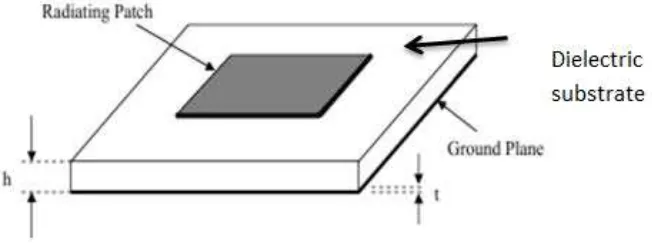
2.1 Parts of microstrip antenna 6
2.2 Directional antenna 9
2.3 Omni-directional antenna 10
2.4 Microstrip line feeding. 11
2.5 Coaxial probe feeding 12
2.6 Aperture Coupled Feeding 13
2.7 Proximate coupled feeding 13
2.8 Structure of coplanar waveguide feed 14
2.9 Types of fractal geometries 16
2.10 Steps of gasket geometry construction 17
2.11 Iteration to obtain Steps Sierspinski carpet geometry 17 2.12 Iteration to obtain steps Koch curve geometry 18
3.1 Flow chart diagram 20
3.2 Antenna A 23
3.3 Antenna B 24
3.4 Antenna C 25
3.5 Form of human arm in axial view 28
3.6 Antenna position on arm model (a) perspective view, (b) front view
29
3.7 Frequency spectrum 30
4.1 Antenna A dimension 33
4.2 Iteration of design antenna A 34
4.3 Result of farfield (a) antenna A(1), (b) antenna A(2) and (c) antenna A(3)
36
xii
4.5 Iteration of design antenna B 38
4.6 Result of farfield (a) antenna B(3), (b) antenna B(3) and (c) antenna B(3)
40
4.7 Antenna C dimension 41
xiii
LIST OF TABLES
No Title Page
1.1 Project Schedule for Final Year Project 4
3.1 Design specification 21
3.2 Characteristic of Fr4 substrates 22
4.1 Antenna A dimension 33
4.2 Antenna B dimension 37
4.3 Antenna C dimension 41
4.4 Comparison of antenna parameters at free space 44 4.5 Comparison of antenna parameters at free space and
on the human arm model conditions
53
4.6 Radiation pattern of the antenna between free space and on the human arm model conditions for antenna A
55
4.7 Radiation pattern of the antenna between free space and on the human arm model conditions for antenna B
56
4.8 Radiation pattern of the antenna between free space and on the human arm model conditions for antenna C
xiv
LIST OF ABBREVIATIONS
c - Velocity of light in free space L - Length of the patch antenna W - Width of the patch antenna Lg -Length of ground
Wg - Length of ground
-Effective relative permittivity
-Relative permittivity
- Desired resonant frequency
h -Substrate thickness
Zo - Characteristic of impedance BW - Bandwidth
RF - radio frequency GSM - Global short massage WLAN - Wireless local area network Fr4 - Flame retardant 4
CST -Computer simulation technology SAR -Specific absorption rate
xv LTE -Long term evolution
LIST OF APPENDIX
No Title Page
1
2
Parameter of antenna on human arm model such as farfield, resonant frequency, directivity and efficiency. Comparison of communication bands.
CHAPTER 1
INTRODUCTION
This chapter will discussed about introduction fractal multiband antenna design for body application. Moreover this chapter also explains about problem statement, objective and scope of work.
1.1Introduction
2
frequency range for mobile application is 3.1 GHz to 10.6 GHz and frequency for Wireless Local Area Network is 2.4 GHz. All of the frequencies have been set up by the Federal Communication Commission (FCC) agency. In order to test the effectiveness of the design antenna, there are seven type of antenna parameters used to measure the antenna performances which are directivity, gain, radiation pattern, efficiency, resonant frequency, return loss and antenna polarization.
This final year project will be studies on the fractal multiband antenna on body application (arm body) parameter that will be observed are such as its gain, bandwidth, return loss and resonant frequency. A fractal antenna is a repetition of a motif design of the antenna with the same or different in sizes. Moreover, fractal antennas are light-weight, low profile, conformal and easy to combine with other circuit structures [1,2]. This type of antenna’s self-similarity can be applied for multiband antenna design. It has been proved that fractal shapes can lead to antenna miniaturization as well as capable to operate at multiband frequencies [3,4]. Fractal shapes is divided into various types such as cantor set, Koch curve, Sierpinski gasket and Sierpinski carpet [5].
1.2 Problem Statement
3
determining which high frequency band suitable for on body application is crucial. This project considered the mobile frequency band due to each of implementation with current communication technology
This project will be analyzing which is the highest frequency band that can be used for medical application. It is because when the frequency is increases, the bandwidth also increases. Besides that, the antenna wavelength is smaller. Objective for these projects are to identify which operating frequency of mobile application has a less effect of power loss density on body application. This project consider the mobile frequency because implement antenna form medical application by follow changing of technology.
1.3 Objective
Objective of this project is to design and simulate multiband antenna (GSM1800, UMTS 2100, Wi-Fi/Bluetooth 2.4GHz, and LTE2600) by using fractal shaped techniques. Besides that, this project to Analysis effect of parameter (return loss, gain, directivity, total efficiency and radiation pattern) between antenna with free space and on human arm model condition. Next is to identify which operating frequency of mobile application has a less effect of power loss density on body application.
1.4Project scope
In order to achieve the objective of the project, there are several scope had been outlined. This project focuses on frequencies that can be function ranging from 0 GHz – 3.0 GHz for mobile communication[6]. Frequency that can cover range for:-
1. GSM900/1800 (880MHz – 915MHz/1710MHz – 1879MHz) 2. UMTS 2100 (1920 MHz-2170MHz)
4
The scope of this project also focuses on Analysis effect of parameter between free space antenna and arm body without consider effect to the body.
[image:19.595.109.538.207.747.2]1.5Project Schedule
Table 1.1: Project Schedule for Final Year Project
PROJECT ACTIVITIES SEMESTER 1 SEMESTER 2
Supervisor meeting Every weeks
Project title selection. week 1 and week 2 Project title registration. Week 2 Producing project proposal. Week 3 until week 5
Submission of project
proposal. Week 4 and week 5
Modeling multiband patch antenna will be conducted by
CST software.
Week 7 until week 19 and
also within semester break Week 1 until week 5 The simulation procedure will
be done for the patch antenna. Week 12 until week 19 and also within semester
break
Week 5 until week 9 Analysis the antenna
parameters on free space condition and redesign. Apply the antenna on human arm model in CST to analyze the suitable frequency body
application. Then compare the parameters of antenna.
Week 7 until week 11
FYP 1 preparation. Week 7 until week 10 Producing Chapter 1, 2 and 3. Week 8 until week 13
Submission of preliminary
report Week 14
Writing Chapter 4 Week 8-week 10
Writing Chapter 5 Week 10 until week 12
CHAPTER 2
LITERATURE REVIEW
2.1. Introduction
The literature review is one of the developer’s methodologies to enhance the understanding of the field research for the developer. Besides that, literature reviews are made for the support of the arguments that are made during this research. Apart from that, the literature review is carried out in order to enable the reader to refer to this section if there is confusion and misunderstanding of some of the terms that are found throughout this research.
2.2. Microstrip Antenna
6
Figure 2.1: Parts of microstrip antenna
By referring to the figure 2.1, h represent the substrate thickness and t represent the thickness. The microstrip antenna is energized only when connected to a microwave ground plane. Then, the charge will arise on the upper patch, lower patch and surface on the ground plane to create a positive and negative charge into field.
7
2.3. Antenna Properties
There are several factors that can determine the performance of the antenna. Those properties are listed:
2.3.1 Gain
The antenna’s gain is a measurement of the antenna overall efficiency. There are many factors that can reduce the antenna overall efficiency. Those factors are impedance matching, material losses, network losses and random losses. In order to achieve acceptable gain performance, the antenna must overcome lot of optimization process obtained a good designed.
2.3.2 Input impedance
Basically, input impedance is to determine maximum power transfer between antenna and the transmission line. The transfer only succeeds when input impedance of the transmission line and antenna is matches otherwise the reflected wave will be generating at the antenna terminal and then flow back to the energy source. The impact of reflection of energy result causes a reduction in efficiency system.
2.3.3 Directivity
8
the same in all direction and usually has directivity of 1. Directivity also can be defined as equation below:
D = Fmax / F0 (2.1) Where,
F0 is a isotropic radiator radiated energy (Hz)
Fmax is a maximum radiated energy (Hz)
2.3.4 Bandwidth
Bandwidth is defines as frequency range over a certain specification performance criteria. The performance tradeoffs between all of its performance properties should be important thing to be concern when it goes to bandwidth. An antenna is considered as a broadband if
FH / fL 2 (2.2)
BWp = (fH – fl) / f0 x 100% (2.3)
BWb = fH / fl (2.4)
Where,
f0 is a operating frequency (Hz)
fl is a lower cut off frequency (Hz)
fH is a higher cut off frequency(Hz)
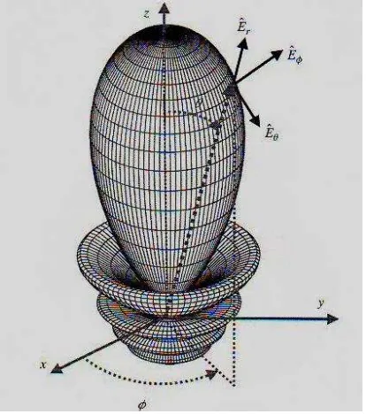
2.3.5 Radiation pattern
9
Radiation properties include power flux density, radiation intensity, field strength, directivity phase or polarization.”[1]. Representation of the radiation properties of the antenna as a function of angular position:
Power pattern: the trace of the angular variation of the received/radiated power at a constant radius from the antenna
Amplitude field pattern: the trace of the spatial variation of the magnitude of electric (magnetic) field at a constant radius from the antenna.
Often the field and power pattern are normalized with respect to their maximum value, yielding normalized field and power patterns. The power pattern is usually plotted on a logarithmic scale or more commonly in decibels (dB). The have 3 type of radiation pattern:-
Isotropic pattern is the pattern of an antenna having equal radiation in all directions. This is an ideal (not physically achievable) concept. However, it is used to define other antenna parameters. It is represented simply by a sphere whose center coincides with the location of the isotropic radiator.
[image:24.595.216.423.504.738.2] Directional antenna is an antenna, which radiates (receives) much more efficiently in some directions than in others. Usually, this term is applied to antennas whose directivity is much higher than that of a half wavelength dipole as shown in Figure 2.2.