EFFECT OF PROCESS PARMAETRS DURING FORMING OF SELF
REINFORCED
–
PP BASED FIBER METAL LAMINATE
S. Kalyanasundaram*, S. DharMalingam †,S. Venkatesan*, A. Sexton*
*
Research School of Engineering Australian National University North Road, Canberra 0200, Australia E-mail: [email protected]
†Faculty of Mechanical Engineering, Universiti Teknikal Malaysia Melaka, Hang Tuah Jaya, 76100
Durian Tunggal, Melaka, Malaysia
Key words: Fiber Metal Laminate, Dome Forming, Real Time Strain Measurement System, Thermoplastic Composites.
Summary. This research presents results on the stamp forming behavior of Fiber Metal Laminate Systems. A Design of Experiments approach was undertaken to elucidate the major effects of the process parameters that include blank holder force and temperature. Evolution of major strain and strain ratio were used as metrics in the analysis. A significant finding from this work is the identification of recrystallization behavior that significantly changed the forming behavior of this class of material systems.
1 INTRODUCTION
Climate change is a subject of growing global concern. Based on International Energy
Agency 2009, research report, about 23% of the CO2 gas emissions from fuel combustion are
generated by the transportation sector and its share is likely to grow. Significant increases in the vehicles fleets are expected particularly in China, India, Middle East and Latin America. The Institute for Energy and Environmental Research (IFEU) study analyzed the potential energy and greenhouse gas savings from transportation sector shows greenhouse gas emissions contribution are very high from on road vehicles. Moreover the United Nations Framework Convention on Climate Change (UNFCCC) has also emphasized transportation sector in general and on-road vehicles in particular as a major source of greenhouse gas emissions, especially in highly industrialized nations. Furthermore vote by the European
parliament on the EU Commission directive proposal concerning reduction of CO2 emissions
from light-duty vehicles confirms the overall awareness that fuel consumption in passenger cars and the resulting emissions should be further reduced. The energy required to power motor vehicles is more than four times than required to produce and recycle them.
greenhouse gas emissions by around nine grams of CO2 equivalent per kilometer, proving that
mass reduction can significantly contribute to the required reduction of greenhouse gas emissions from automobiles.
The usage of lightweight materials such as Fiber reinforced composite materials and metal-composite structures can significantly reduce the weight of vehicles. The main challenge in using these advanced light weight material systems for automotive usage is a suitable manufacturing technique. Stamp forming is widely used in automotive sector to produce body panels of the automobiles. Our current work will present research outcomes on the suitability of this manufacturing technique for mass producing a class of Fiber Metal Laminate Systems (FML). In the past several studies have been carried on the stamp forming behaviour of thermoplastic composites. Bogaerts [1] studied wrinkle formation and the influence of process variables, forming rate, blank temperature and blank holder force factors, on the formability of glass-fiber reinforced PP composites. It is suggested that high temperatures facilitate desirable shearing behaviour; however, this also increases undesirable fiber slipping. Friedrich et al [2] studied the effects of preheat temperature and press closing speed on wrinkle formation. They found that above a certain closing speed, preheat temperature has a dominant influence on wrinkle formation. They also found that in 3D-forming, clamping pressure is essential to achieve satisfactory forming results. It was also observed thickening and thinning is higher in unidirectional reinforced laminates compared to fabric reinforced. Another important phenomenon observed was fiber buckling which occurs in the flange region [3]. Martin et al [4] identified initial fiber orientation, matrix-viscosity blank size and forming speed as contributing to wrinkle formation on the flange. Hwang and Hwang [5] proposed a method of locally heating the stamping region of the blank. Their results suggested that high blank-forming temperatures reduce fiber buckling, delamination and spring back and that the quality of locally heated stamped parts is comparable to the quality of parts that are heated in their entirety before stamping. Lim et al [6] focused on the interaction between stretch and draw behaviour in forming of thermoplastic composite sheets with a knitted-fabric structure. It was concluded that blank forming could be optimised through variation to blank holder force, punch shape and blank size, which effectively varied the amount of stretch and draw present in the forming. Cabrera et al [7] found that, in contrast to traditional continuous woven-glass fabric-reinforced PP materials, where the sole mode of deformation is either inter or intraply shearing, self-reinforced PP composites have an additional mode of deformation, as in that case the fibers can still be deformed. Cao et al. [8] suggested the dominant mechanism in woven-composite forming is the intra-ply shear phenomenon. They used a picture- frame test to highlight the differences in forming varying weave geometries, with a balanced twill-weave fabric requiring a much higher shear force for a given shear angle than either a plain weave or unbalanced twill-weave fabric. Compston et al [9] investigated the surface strain resulting from channel forming of aluminium and preheated FML. It was shown that major strain in the bend regions is much less on the FML channel than on the plain aluminium channel and that the magnitude of the bend radius does not significantly affect the surface strain of the FML.
rectangular cups and channel section. It was found that in the study of the stamp forming of rectangular cups mechanical properties of the constituents have a major influence on the forming characteristics of these material systems. Aluminum/Twintex FML systems exhibited wrinkling as the major failure indicator, with splitting the major failure mechanism for Aluminum/Curv FML systems. This difference in forming behaviour can be attributed to the different flow behaviour of composites during forming. Mosse et al recognise the importance of understanding the synergy between the pre-heat temperature and the mechanical behaviour of the constituents for the successful stamp forming of FML systems [10]. Studies of channel section [11, and 12] recognise significant improvements in shape error when compared with monolithic aluminium formed using the same process. In comparison with aluminium, FML systems show 75% less shape error, suggesting that these material systems could provide benefits in both mechanical properties and ease of forming, with analysis of bend radii revealing that the normalised deviation in bend radius from the tool radius is constant for the range of radii investigated. Their study [12] also indicates that for a set forming temperature, feed-rate followed by blank-holder force are the process variables in achieving good formability.
Gresham et al [13] investigated the drawing behaviour of metal–composite sandwich
structures as a function of the constituent material properties and the process variables of blank preheat temperature and blank-holder force. They identified that blank-holder force has a significant effect on the failure mode of the metal–composite system with lower forces resulting in wrinkling as the dominate mode and higher forces resulting in splitting and fracture. Increasing preheat temperature decreases the failure in the composite core, however, it increases the severity of wrinkling in the outer flange and sidewall. A finite element model
for simulating the stamp-forming of fiber–metal laminate material systems (Twintex-FML)
was developed to investigate the composite–metal interaction by studying the crystallisation
behaviour of the interlayer adhesive and its shear stress transfer characteristics using lap-shear apparatus [14]. Sexton et al. [15] investigated the deformation behaviour of a FML based on a self-reinforced polypropylene composite. This study found that the FML exhibited a greater strain at failure and an increased forming window. In addition, it was found that the FML system displayed a more even thickness distribution compared to a similarly formed metal part.
This study will present the effect of process parameters (blank holder force, temperature and feed rate) on the forming of a dome structure comprised of a FML system. The material system is comprised of alternating layers of aluminium and a self-reinforced polypropylene composite material system. The experimental values for strain evolution during forming were carried through a real time strain measurement system using a 3D photogrammetry method.
2 EXPERIMENTAL PROCEDURES
the dome geometry. Forming action was performed using a hydraulic ram with a stroke length of 200mm. A blank holder was coupled with the press to hold down the composite sheet during the forming process and had a maximum holding force of 14kN. To record the punch force, a 150kN compression load cell was mounted in line with the punch and a potentiometer was used to measure the displacement. This study employs biaxial forming to investigate two of the main forming modes that commonly occur, namely stretching and drawing. Hemispherical-shaped punch is used to produce the necessary forming modes. A 2/1-aluminium/composite FML was used for the experimental work in this study. The inner layer
of laminate consisted of 1mm thick self-reinforced polypropylene, CurvTM, produced by
Propex Fabrics, Germany. CurvTM is an outstanding new material that combines the versatility
of a 100% thermoplastic with the high performance of a fiber-reinforced composite. Two
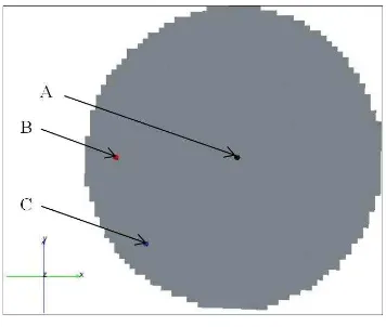
layers of 50 μm thick hot-melt polypropylene adhesive (Gluco) were applied to each bi-material interface. The laminate was placed in a heat press and heated to the Gluco-bonding temperature range of 155°C-165°C with 0.4MPa applied pressure. The laminate was water cooled to 50°C at a rate of 50-70°C/min before removal. A final FML with a nominal thickness of 2mm was achieved. The FMLs were cut into circular blanks of diameter 180mm using water-jet cutting. This FML system gives a weight reduction of almost 30% compared to 2 mm thick 5005 H34 monolithic aluminium. An open die configuration was chosen to provide for the coupling of 3D strain measurement system (ARAMIS) manufactured by GOM, mbH, Germany, which provides deformation and strain analysis using 3D image correlation. The system provides a full field strain measurement using photogrammetric method as the samples are being tested. Figure 1 is a schematic diagram elucidating the terminologies that will be used henceforth to describe the locations on the formed blank.
Figure 1: Location terminology on the blank during forming [16]
For the evolution of strain during forming using the ARAMIS system, three points of interest had been selected:
i. Point A, at the pole to study biaxial stretch during forming.
ii. Point B, 40mm along the fiber-orientation direction from the pole to study plane
iii. Point C, 40mm from the pole at an angle of 45° from the fiber-orientation, to capture shearing effects during forming since shearing is a dominant deformation mode in woven composites.
Point A is located at the pole of the punch face, while both points B and C are located at the side wall of the dome during forming. Figure 2 illustrates the locations of the three points chosen to represent deformation behavior of interest on the ARAMIS system.
Figure 2: Points of interest in the blank [16]
In the present study, full factorial experiments were conducted to have comprehensive account for all factors effects on strain evolution. This work used the factors and level shown in Table 1 giving a total of 63 experimental cases.
Factors Levels
Temperature (°C) 25, 60, 80, 100, 130, 140, 150
Feed rate (mm/s) 10, 20, 40
Binder force (kN) 2, 7, 14
Table 1: Experimental design of process parameters
3 RESULTS AND DISCUSSIONS
sudden increases in major strain values indicate the regions of possible failure. Strain ratio (minor strain/major strain) is also selected as a metric for forming since this measure provides a convenient description of the deformation mode during forming.
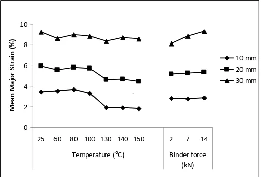
3.1 Effect of process parameters on major strain evolution at point A
Figure 3 illustrates the increase in major strain as depth increases. This figure suggests that there is an ongoing stretch deformation at the pole throughout the forming process. Up to a depth of 20 mm, temperature effects can be categorized into two groups. First includes a
lower-temperature group between 25oC to 100oC. The second is a higher-temperature group
between 130oC to 150oC. This grouping correlates well with the Gluco recrystallization temperature, which is between 120oC to 100oC. At high temperature, the glue is in “melt” condition where the FML layers can slide on top of one another and at low temperatures, the FML layers are intact and acts as one thick layer.
Figure 3: Main-factor effects at point A for mean major strain at different depths
3.1.1 Effect of temperature on the major strain
The lower temperature group has an overall higher mean major strain compared to the higher temperature group. It is interesting to note that this difference in the mean major strain values decreases with increasing depth and is depicted in Figure 3. The trends in the major strain evolution at different depths can be characterised by the relative changes at different depths. It is also observed that as the forming depth increases, the average mean major strain increment reduces. For the low-temperature group, increase in the average mean major strain from 10 mm to 20mm is 64.5% and from 20mm to 30 mm it is 54.7%. For the high- temperature group the increase is in the order of 145.2% followed by 86.4%. Several conclusions can be drawn from Figure 3. The average mean major strain increment reduces with increase in depth. The low-temperature group average mean major strain increment is lower than the high-temperature group which explains the equalization of the mean major strain in the two groups as the depth increases to 30mm. The reduction of the average major
strain increment can be attributed to several factors that include strain hardening of the FML as the depth increases, which will require more force to maintain the same rate of strain increment. In addition, as the forming-depth increases the area of contact between the FML and punch face increases. The increase in the contact area increases the friction force between the contacting surfaces. With a high friction force, higher punch force is required to continue to deform the pole. Finally, for a preheated FML, the contact time between the tool and FML increases with depth, leading to a cooling of the laminate which reduces the temperature effect during forming.
In comparing the two temperature groups, the mean major-strain increment was observed to be higher in the high-temperature group compared with the low-temperature group. This leads to two important observations: Firstly, the high temperature group has a very significant effect on mean major strain, which in return, will affect formability. This is due to the softening of the composite layer which will reduce the bending stiffness of the material system. Secondly, the high temperature group will also have a significant contribution with
added influence from the “melt” condition of the glue. This is seen in the higher average mean
major strain increment.
It can be observed from the comparison of the strain measurements between the two temperature groups that there is a difference in the mode of forming. In the high-temperature group, the laminate is less stiff and glue is in the “melt” condition. The glue moves from a
completely “melt” condition to recrystallization between 120°C and 100°C., It is hypothesised
that during this phase change there is a significant change in the friction between the composite and the metal layers. This friction increases from an insignificant value during the melt phase to a higher value when recrystallised. When the friction between the layers of the blank is very low, the movement between the layers is unrestricted. This allows for the sliding of one layer over another. This movement between the layers results in drawing of the blank instead of stretching. This draw is also influenced by the lower bending-stiffness of the now independent layers and softer composite due to high temperature. The drawing of the blank results in the lower mean major-strain measurements. In comparison, the low-temperature laminate are seem to be still intact due to the solid phase of the glue. It is also far stiffer than at higher temperatures. In this phase, the forming mode is dominated by stretch forming.
3.1.2 Effect of binder force on the major strain.
3.2 Effect of forming parameters on strain ratio at point A
In considering temperature effects on strain ratios at point A, we can see from Figure 4 that the mean-strain ratio ranges from 0.82 to 0.95, which is well within the metal biaxial stretch region, 0 < β < 1.0, and balanced biaxial is given by a strain ratio of 1.0. As found in the major-strain analysis the strain ratio at point A also shows the same two temperature groups.
Figure 4: Main-factor effects at point A for mean strain ratios at different depths
3.2.1 Effect of temperature on strain ratio at point A
Within the low temperature group, mean strain ratio ranges from 0.82 to 0.95 while in the high-temperature group it ranges from 0.83 to 0.88. Close to balance biaxial stretch could be reached only at room temperature (25°C) at a depth of 10 mm. At 20mm and 30mm depth the average mean strain ratio is almost similar for both temperature groups. In the low-temperature group, the average mean strain ratio reduces as depth increases with the following rate, 6.1% from 10mm to 20mm and 2.7% from 20mm to 30mm. Reduction of the average mean-strain ratio indicates that the forming mode is converging away from balanced biaxial stretch as depth increases. It is also observed that for each depth only the mean-strain ratio at room-temperature is the highest, and as the sample is preheated, from a range of 60°C-100°C, the mean-strain ratio reaches a plateau. Any preheat under the glue melt condition gives almost the same mean-strain ratios at their respective depths. For the high-temperature group, the mean-strain ratio remains constant at approximately 0.83 for forming temperature 130°C, while at 150°C it converges to 0.88. For the high-temperature group the average mean-strain ratio also reduces as depth increases. The decrease in average mean-strain ratio is as follows, 1.25% from 10mm to 20mm and 0.1% from 20mm to 30mm. This indicates that the average mean-strain ratio converges as depth increases as was found in the low-temperature group. The high-low-temperature group mean-strain ratio moves from 0.83 to 0.88, showing that the material system has a more balanced biaxial strain increment as the temperature increases. Comparing the strain-ratio window between the depths, the low-temperature group has a larger mean-strain ratio window, 0.82 to 0.95, from 10mm to 30mm
forming depth while the high temperature group has a small mean strain ratio window, 0.83 to 0.88, for the same depth, showing that there is no sudden change in the strain path. This observation supports our previous hypothesis that the softening of the composite layer, reduction in the stiffness at high temperature and the glue melt condition do affect the formability of this material system.
3.2.2 Effect of binder force on the strain ratio at point A
The binder force level does not exhibit a significant effect on the mean-strain ratio at the lower forming depth, 10mm. Low binder force, 2kN, results in a similar mean- strain ratio throughout the forming depth up to 10 mm. Higher binder forces, 7kN and 14kN, display significant effects on the mean-strain ratios beyond the forming depth of 10mm. The binder force has a discounted effect on the mean strain ratio. As the binder force increases, the mean-strain ratio moves from 0.9 to 0.8, indicating that the forming mode is moving away from balanced biaxial towards biaxial.
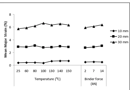
3.3 Effect of forming parameters on major strain at point B
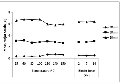
Figure 5 illustrates the effect temperature and binder force on major strains at different depths. The figure illustrates an increase in mean major strain with increasing depth. This indicates a stretch forming behaviour at point B for various depths.
Figure 5: Main factor effects at point B for mean major strain at different depths
3.3.1 Effect of temperature on the major strain at point B
In analysis of the main effect of temperature, it is noticeable that the two groups of temperature are present at a depth of 10 mm. But this grouping of temperatures is not very significant. This grouping cannot be observed at depths beyond 10 mm. The average mean major strain experiences an increase of 485% from 10 mm to 20 mm and 116% from 20 mm to 30 mm. This percentage of increase in average major strain is far higher than that observed for point A. As the forming depth increases the area of contact between the FML and punch
face increases, with the increase in the contact area increasing the friction force. With high friction force, higher force is required to increase the extension at point A while point B is still not in contact with the punch face up to the 30 mm depth. This allows for a smaller force to give a higher increase in the average mean major strain. It is also observed that the mean major strain for Point B is always lower than mean major strain at Point A, indicating that stretch at point B is smaller compared with biaxial stretch. This is because the reference depth is taken at point A, and as such point B does not experience the same displacement that is experienced by point A.
3.3.2 Effect of binder force on the major strain at point B
Binder force effects are prominent at depths of 10 mm and 30 mm. An increase in binder force increases the mean major strain at all three depths of interest. Higher binder force increases stretch and results in increased strain. Average mean major strain increases by 485% from 10 mm to 20 mm and 116% from 20 mm to 30 mm. This is very similar to the average mean-strain increment with temperature effect.
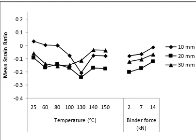
3.4 Effect of forming parameters on strain ratio at point B
Figure 6 illustrates the main factor effects at point b for strain ratios at different depths. The same two temperature groups are observed for the effect of temperature on the mean strain ratio at all the depths studied.
Figure 6: Main factor effects at point B for mean strain ratios at different depths
3.4.1 Effect of temperature on the strain ratio at point B
At the depth of 10 mm, in the low-temperature group, forming is dominated by plane strain, while in the high-temperature group there is draw. Beyond a depth of 10 mm, the strain ratio measurements converge to a value of -0.15 in the low-temperature group. This indicates that in the mode of draw, forming is driven by an increase in depth in the low-temperature group. In the high-temperature group, the strain ratio increases with an increase in temperature from 130°C to 140°C. At temperatures above 140°C, the strain ratio forms a plateau. Furthermore, as the depth increases the draw-forming mode reduces.
3.4.2 Effect of binder force on the strain ratio at point B
An increase in binder force increases the mean strain ratio, while increase in depth also increases the mean strain ratio. At 10 mm depth forming is dominated by plane strain while at depths of 20 mm and 30 mm forming is dominated by draw, and as the depth increases from 20mm the draw-forming component reduces. Higher binder force also contributes to moving the forming mode faster from draw forming towards plane-strain forming.
3.5 Effect of forming parameters on major strain at point C
Figure 7 illustrates the main factor effects at point C for mean major strain at different depths. It can be seen that mean major strain increases as the depth increases, indicating that stretch occurs throughout the forming process. Point B and point C are on the same circumference and the only difference is the composite woven angle. Both show almost similar trends and similar mean major strain up to the depth of 20mm. At a depth of 30 mm there is a clear temperature-group effect at point C which is not seen at point B. Moreover, at this depth average mean major strain for the low temperature group for point C is higher than that for point B. This is evidence that even though points B and C are at the same meridinal distance from pole the deformation is driven by a different mechanism.
Figure 7: Main factor effects at point C for mean major strain at different depths
3.5.1 Effect of temperature on major strain at point C
3.5.1 Effect of binder force on major strain at point C
Increase in the forming depth increases the mean major strain. The average mean major-strain increase is 478% from 10mm to 20mm and 121% from 20mm to 30mm. Similar values were also observed at Point B. The mean major-strain values with respect to binder force are similar to values at B. While increase in binder force has effect at point B from 10mm, this effect is only prominent for point C at 30mm depth. This could be attributed to the fiber orientation at the points of reference. At point B, which is along the fiber-direction, binder-force values will determine the stretch of the fiber, while at point C deformation is dominated by intraply shear.
4 CONCLUSIONS
Based on the statistical analysis of the main factors, temperature, binder force, feed rate and interaction effects on major-strain and strain ratios, it can be concluded that only the independent factors temperature and binder force have significant effect on major strain and strain ratios. Also, the temperature effects can be categorised in two groups, A lower-temperature group between 25°C to 100°C and a higher-lower-temperature group between 130°C to 150°C. This grouping correlates well with the Gluco recrystallization temperature between
120°C to 100°C. At high temperatures the glue is in a “melt” condition where the FML layers
can slide easily on top of one another and in the low-temperature group the FML layers are intact and acts as one thick layer. Increase in binder force increases the major strain value and influences strain ratios. It can be concluded that the strain experienced by the FML system is affected by binder force, stiffness of the composite and glue state.
REFERENCES
[1] L. Bogaerts, M. Lossie and D. Vandepitte, “Deepdrawing of composite sheet materials”, Proceedings of 9th International Conference on Sheet Metal, 127-134, Leuven, Belgium, April 2001.
[2] K. Friedrich and M. Hou, “On stamp forming of curved and flexible geometry components from continuous glass fiber/polypropylene composites”, Composites Part A: Applied Science and Manufacturing, 29(3):217-226, 1998.
[3] K. Friedrich, M. Hou and J. Krebs, “Chapter 4- Thermoforming of continuous
fibre/thermoplastic composite sheet, 11, 91-162, Elsevier, 1997.
[4] T. A. Martin, D. Bhattacharyya and R.B. Pipes, “Deformation characteristics and
formability of fibre-reinforced thermoplastic sheets”, Composites Manufacturing,
3(3):165-172, 1992.
[5] S. Hwang and K. Hwang, “Stamp forming of locally heated thermoplastic composites”, Composites Part A: Applied Science and Manufacturing, 33(5):669-676, 2002.
[6] T. C. Lim, S. Ramakrishna, and H.M. Shang, “Axisymmetric sheet forming of knitted fabric composite be combined stretch forming and deep drawing”, Composites Part B: Engineering, 30(5):495-502, 1999
[7] N. O. Cabrera, C. T. Reynolds, B. Alcock and T. Peijs, “Non-isothermal stamp forming of
Applied Science and Manufacturing, 39(9):1455-1466, 2008.
[8] J. Cao, R. Akkerman, P. Boisse, J. Chen, H.S Cheng, E. F. de Graaf, J. L. Gorczyca, P. Harrison, G. Hivet, J. Launay, W. Lee, L. Liu, S. V. Lomov, A. Long, E. de Luycker, F. Morestin, J. Padvoiskis, X. Q. Peng, J. Sherwood, T. Stoilova, X. M. Tao, I. Verpoest, A.
Willems, J. Wiggers, T. X. and B. Zhu, “Characterization of mechanical behavior of woven fabrics: Experimental methods and benchmark results”, Composites Part A: Applied Science and Manufacturing, 39(6):1037-1053, 2008.
[9] P. Compston, W.J. Cantwell, M.J. Cardew-Hall, S. Kalyanasundaram and L. Mosse,
“Comparison of surface strain for stamp formed aluminum and an aluminium
-polypropylene laminate”, Journal of Materials Science, 39(19):6087-6088, 2004.
[10] L. Mosse, W.J. Cantwell, M.J. Cardew-Hall, P. Compston and S. Kalyanasundaram, “A
study of the effect of process variables on the stamp forming of rectangular cups using
fibre-metal laminate systems”, Advanced Materials Research, 6-8:649-656, 2005.
[11] L. Mosse, P. Compston, W.J. Cantwell, M.J. Cardew-Hall and S. Kalyanasundaram,
“The effect of process temperature on the formability of polypropylene based fibre-metal
laminates”, Composites Part A: Applied Science and Manufacturing, 36(8):1158-1166, 2005.
[12] L. Mosse, P. Compston, W.J. Cantwell, M.J. Cardew-Hall and S. Kalyanasundaram,
“Stamp forming of polypropylene based fibre-metal laminates: the effect of process
variables on formability”, Journal of Materials Processing Technology, 172(2):163-168, 2006.
[13] J. Gresham, W.J. Cantwell, M.J. Cardew-Hall, P. Compston and S. Kalyanasundaram,
“Drawing behavior of metal-composite sandwich structures”, Composite Structures,
75(1-4):305-312, 2006.
[14] L. Mosse, P. Compston, W.J. Cantwell, M.J. Cardew-Hall and S. Kalyanasundaram,
“The development of a finite element model for simulating the stamp forming of fibre
-metal laminates”, Composite Structures, 75(1-4):298-304, 2006.
[15] A. Sexton, W.J. Cantwell and S. Kalyanasundaram, “Stretch forming studies on a fibre
metal laminate based on a self-reinforcing polypropylene composite”, Composite
Structures, 94, 431-437 (2012).
![Figure 1: Location terminology on the blank during forming [16]](https://thumb-ap.123doks.com/thumbv2/123dok/573102.67888/4.595.120.475.459.588/figure-location-terminology-blank-forming.webp)