RF CONTROL OF A MULTI-TASKING VEHICLE
AHMAD KHAIRUL FAZLI BIN NADZRI
BACHELOR’S DEGREE IN ELECTRICAL ENGINEERING (INDUSTRIAL POWER))
RF CONTROL OF A MULTI-TASKING VEHICLE
AHMAD KHAIRUL FAZLI BIN NADZRI
This Report Is Submitted In Partial Fulfillment of Requirements for the Degree of Bachelor in Electrical Engineering
(Indusrial Power)
Faculty Of Electrical Engineering
UNIVERSITI TEKNIKAL MALAYSIA MELAKA
“I hereby declared that I have read through this report and found that it has comply the partial fulfillment for awarding the degree of Bachelor in Electrical Engineering (Industrial Power)”
Signature : ………
Supervisor’s Name : Mr. Hyreil Anuar Bin Haji Kasdirin
iii
“I hereby declared that this report is a result of my own research except as
cited clearly in the references. The report has not been accepted for any degree and
concurrently submitted in candidature of any other degree”
Signature : ………
Name : Ahmad Khairul Fazli Bin Nadzri
Matrix Number : B010510124
iv
For my beloved father and mother Nadzri Bin Isa and Ch Rohni Binti Ch Soh
v
ACKNOWLEDGEMENTS
In the name of Allah, The Beneficent, The Merciful.
Alhamdulillah, all praise is to Allah that I have been able to complete my report for my
“Projek Sarjana Muda 2” that is RF Control of a Multitasking vehicle.
My highest appreciation and sincere gratitude regarded to Mr. Hyreil Anuar Bin Kasdirin for his invaluable help, support and ideas as my supervisor in achieving my “Projek Sarjana Muda 2” goals. His entire guides throughout this project are hope to be remain for generation to come.
During the completion, I had collaborated with many colleagues and friends, for whom I have great regards and I want to extend my warmest thanks to all those who helped me with my project.
Finally, I would like to give an honor to my parent, for supporting me in not only in
this project but in my entire life. It’s a great honor for me to be your son.
vi
ABSTRACT
The main objective of this project is to design and develop a manual control of multi-tasking vacuum to be controlled by Radio Frequency (RF) or wireless communication system. Now, the development of technology made the world to has unlimited borders which make the people lifestyle much easier. In this paper, the project will be targeted into how to make a wireless communication to the vehicle that is Radio-Controlled (RC) car by using a Programmable Interface Controller (PIC16F877A) and potentiometer as the joystick. It describes the development of control method that attempt to fulfilled human desire which in simple example, conducting the device by just click the finger on. The project is focusing on the movement of the vehicle in four ways that are reverse, forward, left, and right. It is to make RF function by using encoder to encode the serial data from the PIC of transmitter circuit to the transmitter. Then, the decoder is used to decode the serial data that is received from the
receiver and the data is sent to another same PIC of receiver circuit. PIC and RF module plays an
important role to fulfill the objective of this project.The last part is the multi-tasking vacuum is attached to the vehicle. The direct current supply of 5Vdc is given in order to run the circuit and the movement of the vehicle is determined by potentiometers that act as the joystick. It comes to firm hardware and software development. The usage of the project is to present such
vii
ABSTRAK
ix
2.3.4 Stepper Motor 16
2.3.5 Direct Current Motor (DC Motor) 18
3 METHODOLOGY 21
3.2.5 Direct Current Motor (DC Motor) 29 3.3 Hardware Implementation 30
3.4.3 Simulation the circuit using Proteus Professional 7 35
3.5 Application 36
4 HARDWARE VERIFICATION AND EXPERIMENTAL RESULT 39
4.1 Introduction 39 4.6.2 Programming the Transmitter and Receiver 45 4.6.3 Programming the Potentiometer 46
x
4.6.5 Programming the Stepper Motor 50
4.6.6 Programming the DC Motor 51
4.7 Application 53
5 CONCLUSION AND RECOMMENDATION 55
5.1 Overview 55
5.2 Problem and Solution 55
5.3 Conclusion 56
5.4 Future Recommendation 56
REFERENCES 58
xi
LIST OF TABLES
TABLE TITLE PAGE
3.1 Single Stepping Sequence 28
3.2 High Torque Stepping Sequence 28
3.3 Half Stepping Sequence 29
4.1 LCD Operation with condition 43
4.2 Specified Modifier 47
xii
2.7 Construction of a wire-wound circular potentiometer 10 2.8 A typical single turn potentiometer 11
2.9 PIC 16F877A 13
2.10 Schematic Diagram of PIC16F877A 13
2.11 Program Memory Map and Stack of PIC16F877A 14
3.10 Development of Transmitter Board 30
xiii
3.12 PICBasic Pro Compilers (Micro Code Studio) 32 3.13 Flowchart of the Transmitter board 33
3.14 Flowchart of the Receiver board 34
3.15 WinPIC Programmer Software 35
3.16 Proteus Professional 7.1 36
3.17 The toy car 36
3.18 Implementing Receiver Board into the model 37 3.19 The stepper motor is implemented after modified 38
4.1 Power Supply Output Voltage 40
4.2 Transmitter Reading 40
4.3 Receiver Reading 41
4.4 Transmitter and Receiver Reading 41
4.5 The upper line visible 42
4.6 The upper and lower line display 42
4.7 Change the angle 43
4.8 Change the movement 43
4.9 The Simulation of PIC Free Running Test 45
4.10 The Simulation of LCD 50
4.11 The Simulation of Stepper Motor 51
4.12 Complete model of the car 53
4.13 12Vdc Rechargeable battery 53
xiv
LIST OF APPENDICES
APPENDIX TITLE PAGE
A1 Full Transmitter Schematic Circuit 60 A2 Full Receiver Schematic Circuit 61
B1 Transmitter Programming 63
B2 Receiver Programming 67
C1 PIC16F877A 72
C2 ULN2003A 74
C3 L293B 75
C4 HT-12E 76
1
CHAPTER 1
INTRODUCTION
1.1 Overview
Radio Frequency or wireless communication describes the development of control method that attempt to fulfilled human desire which is to make their life easier such as by control the device they want by the fingers. Wireless communication is the transfer of information
over a distance without the use of electrical conductors or wires. Advances in computation
technology and communication networks help provide the necessary in implementation for this project.
Realizing this problem, an idea to design and develop a manual control of multi-tasking vacuum to be controlled by using Radio Frequency (RF) or wireless communication
system is come out. The project is “RF Control of multi-tasking vehicle”.
2
1.2 Problem statement
There are a lot of people that want to do their work that ask them to make a move. As an example, they want to clean the house using vacuum without moving their body to that place they have to. This project is developed to help them to clean and scout the surrounding inside the house without using their power themselves.
1.3 Objective
The main objective of this project is to build a device using analog potentiometer as a joystick that can control a vehicle maneuver and movement of a vehicle. The joystick is controlling the vehicle using radio frequency and Liquid Crystal Display (LCD) can act as angle and movement indicator of the vehicle. Otherwise, it is used to carry the multi-tasking vacuum which had developed before.
1.4 Scope
This project is focused to design and build the model of a remote control and a model car that would be used to clean and scout the surrounding inside the house. Therefore, this model will cover the scope as followed:
(i) The vehicle can move forward, reverse, left and right.
(ii) The degree movement of the vehicle can be control precisely.
1.5 Review of the Thesis Content
3
Chapter 2 will describe about the input, controller, the output of the system and the previous similar project. It will explain about the concept of the components that are used in the project.
Chapter 3 includes the project methodology. It will explain how the project is organized and the flow of process in completing this project. Also in this topic discusses the methodology of the system, circuit design, software design and the mechanical design.
Chapter 4 will be discussing about the result obtained in this project and a discussion about the result. This chapter also discuss about the hardware verification and experimental result, expected performance and performance limit that can be archive.
4
CHAPTER 2
LITERATURE REVIEW
2.1 Overview
This chapter reviews about previous system that has been developed and has similarities with the remote control of a moving vehicle. This topic will also discuss about the component that will be used in developing this systems.
2.2 Available Remote Control Car
2.2.1 Ruf Bot 1.1
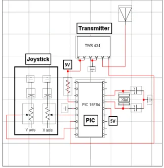
The article is about constructing a car that can be controlled using joystick. The project is called the Ruf Bot. It is made from a 4 x 8 piece of plastic sheet and has modified servos for motors. The servos are modified in a way that makes them DC gear head motors. The servos internal electronics have been completely removed and only the motor and gears remain (hence the need for an H-Bridge).
The project uses TX/RX pair and the serial communication built into the PIC Basic programming language for the PIC's. The actual programming couldn't be easier since it is written in Basic and uses premade serial communication routines.
5
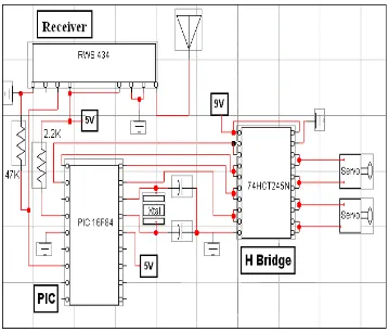
'B0' are sent using the 'SEROUT' command to pin 6 of the TWS 434 transmitter. On the receiver end, the 'SERIN' command is use to read the incoming data from pin 3 on the RWS 434 and the result is store in 'B0'. The value in 'B0' directly correlates to joystick position, above 150 is right, below 106 is left, and in between is center. By using these numbers a dead zone can be define.
The implication is easier at this point. From the number that is transmitted we can determine the movement of the vehicle. By using the antenna that is made for 900 MHz cordless telephones, the vehicle can be control within the range of 350 feet. The circuit and the model of the project are shown in Figure 2.1, 2.2 and 2.3 below.
6
Figure 2.2: Receiver Circuit
7
2.2.2 Toy Car Hack - "Synthetic Rodent Development"
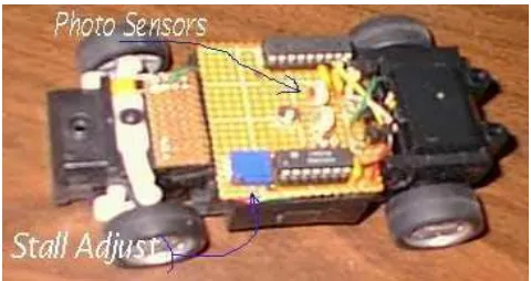
This article is about making a light follower toy car. The toy car will follow the light that is beam to the car. It will determine whether the light came from the left, right or center. The car will stop when an object has been hit. The car is built in 5 inches in length. It is powered by 4 AAA batteries and it has a small dc motor. After gutting the original electronics, a piece of circuit board was cut to size and mounted with one screw. The circuit board is pad-per-hole type and the wiring on the bottom is done with tiny pieces of 30 gauge (wire wrap) wire soldered between points.
Visual detection is done using a pair of (matched) photocells. This type of cell works at even very low light levels. The light sources can be determined to be from left, right, or center using a pair in series feeding a 3 level comparator circuit. The photo cells are physically located to 'look' through a hole drilled in the black plastic windshield.
The motor drive circuit has an adjustable current level detector. This detects motor 'stalls' and is used to determine when an object has been hit. To save power in 'sleep' mode, the PIC powers down the entire external circuit (the op-amp and associated resistor networks) when not needed. A permanent magnet 'floats' on a pair of pivots and is held centered by being attracted to a fixed set of metal pole pieces. When power is applied to the solenoid, the pole pieces move the magnet to the left or right. The toy car hack model is shown in Figure 2.4 below.
8
2.2.3 Final Project - RC Car Controller
The article is about building a transmitter and receiver modules for a radio-controlled (RC) car, as well as implements variable-speed motor control and a continuous steering function. The original implementation of speed control in the car consists of a servo which mechanically moves the arm of a simple high-power potentiometer. While the motion of the servo is continuous, the circuit only produces six discrete levels: three forward, two reverse, and neutral.
A simple communication protocol was established to send messages from the controller to the car. Because the connection is serial, each command are encoded into a byte-long packet. The top nibble denotes the command, and the lower nibble represents the level at which the command is to be executed. For discrete operations (like headlights), the second nibble determines which functions are to be toggled. Communication travels one way from the controller to the car, which cuts down on the hardware required for either unit.
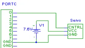
The original controller used spring centered potentiometers to produce analog signals which controlled the speed and direction of the car. The analog signals were transmitted to the car via a 75 MHz AM radio link. The steering of the car is controlled by a servo. Rather than supplying a simple voltage, servos operate on a fixed voltage source and a control line that is pulsed to dictate the turn angle. The servo is connected to the MCU. A Timer interrupt subroutine is used in conjunction with user input from the transmitter to determine the pulse width to be applied and sent through the MCU's port pins. Figure 2.5 show the steering control circuit.
9
The received four-bit digital signal denotes the desired speed of the motor. The motor is drive at full voltage and pulse width modulation is used to control speed. Several products exist which accomplish this task; however, it is a simple matter to implement PWM on the
microcontroller. A timer interrupt is used to count 16 “ticks”, and the given magnitude determined how many of those ticks the motor will be driven.
The joystick is able to move the car forwards and back, and turn left and right. The pulse width modulation, as it was originally conceived, was far too fast for the motor to turn at all. Slowing down the period to approximately one second, up from 1 millisecond, solved the problem. There was some initial irregularity in the pulse itself; instead of regular intervals, it seemed as though the pulses were being interrupted by some external stimulus. Careful programming to avoid register clobbering solved much of the problem, but irregularities occasionally appear at unpredictable times.
Turning the car is nicely variable but not particularly smooth. The same irregularities found in the speed control manifest themselves to a greater extent in the servo, causing the wheels to jerk slightly left and right of the desired turn angle. The problem to be extremely difficult to solve with the Atmel MCU, as pulse widths for the servo vary from 1 to 2 milliseconds; at those small periods, it is difficult to get very accurate timing with the Timer0 interrupt. Thus, it perhaps an Integrated Circuit (IC) 555 circuit would have solved this problem.