OPTIMIZATION OF 5.8 GHz FRONT END RECEIVERS FOR WiMAX APPLICATION
MUZAFFAR BIN MUSTAFFA
This report is submitted in partial of the requirement for the award of Bachelor of Electronic Engineering (Telecommunication Electronics) With Honours
Faculty of Electronic and Computer Engineering Universiti Teknikal Malaysia Melaka
ii
UNIVERSTI TEKNIKAL MALAYSIA MELAKA
FAKULTI KEJURUTERAAN ELEKTRONIK DAN KEJURUTERAAN KOMPUTER
BORANG PENGESAHAN STATUS LAPORAN PROJEK SARJANA MUDA II
Tajuk Projek : OPTIMIZATION OF 5.8 GHz FRONT END RECEIVERS FOR WiMAX APPLICATION
Sesi
Pengajian : 2006/2009
Saya MUZAFFAR BIN MUSTAFFA
mengaku membenarkan Laporan Projek Sarjana Muda ini disimpan di Perpustakaan dengan syarat-syarat kegunaan seperti berikut:
1. Laporan adalah hakmilik Universiti Teknikal Malaysia Melaka.
2. Perpustakaan dibenarkan membuat salinan untuk tujuan pengajian sahaja.
3. Perpustakaan dibenarkan membuat salinan laporan ini sebagai bahan pertukaran antara institusi
pengajian tinggi.
4. Sila tandakan ( √ ) :
SULIT*
(Mengandungi maklumat yang berdarjah keselamatan atau kepentingan Malaysia seperti yang termaktub di dalam AKTA RAHSIA RASMI 1972)
TERHAD* (Mengandungi maklumat terhad yang telah ditentukan oleh organisasi/badan di mana penyelidikan dijalankan)
TIDAK TERHAD
Disahkan oleh:
__________________________ ___________________________________ (TANDATANGAN PENULIS) (COP DAN TANDATANGAN PENYELIA)
Alamat Tetap: 12 JALAN SELASIH 15, TAMAN SELASIH 68100 BATU CAVES SELANGOR
iii
“I hereby declare that this report is the result of my own work except for quotes as cited in the reference”
iv
“I hereby declare that I have read this report and in my opinion this report is sufficient in terms scope and quality for the award of Bachelor of Electronic Engineering (Computer
Engineering) With Honours”
v
vi
ACKNOWLEDGEMENTS
vii
ABSTRACT
viii
ABSTRAK
ix
CONTENTS
CHAPTER TITLE PAGES
PROJECT TITLE i
STATUS REPORT FORM ii
STUDENT DECLARATION iii
SUPERVISOR DECLARATION iv
DEDICATION v
ACKNOWLEDGEMENT vi
ABSTRACT vii
CONTENT ix
LIST OF TABLE xii
LIST OF FIGURE xiii
LIST OF ABBREVIATIONS xv
I INTRODUCTION
1.1 Project Introduction 1
1.2 Objective 2
1.3 Problem Statement 3
x
1.5 Methodology 4
1.6 Report Structure 4
II LITERATURE REVIEW
2.1 Inroduction to WiMAX 6
2.2 RF Front End Block Diagram 8
2.3 LNA Design 9
2.4 DC Biasing Technique 9
2.5 Stability 11
2.5.1 Consideration for stability in high frequency
amplifier design 11 2.5.2 Stability Decision 11
2.6 Gains 13
2.6.1Two-Port Power Gain 13
2.7 Noise in Amplifiers 17
2.8 Input and Output Matching. 19
2.9 Related Software 20
2.9.1 MathCAD Software 20
2.9.2 Ansoft Designer SV 22
2.9.2.1 Analysis 22
2.9.2.2 Features 23
2.9.3 Agilent Advance Design Systems 23 2.9.4 AWR Microwave Office 24
2.9.5 Software Decision 25
III RESEARCH METHODOLOGY
3.1 Understanding the project 26
xi
3.2.1 Mathcad Calculation Steps 28 3.3 Simulation of designed amplifier circuit 30 3.3.1 ADS Simulation Steps 30
3.4 Result Discussion 38
IV RESULT ANALYSIS
4.1 Transistor Selection 40
4.2 Analytical Analysis 42
4.2.1 Stability 42
4.2.2 Gain 43
4.2.3 Noise figure 44
4.3 Simulation Analysis 45
4.3.1 Low Noise Amplifier Simulation 45 4.3.2 Front End Receiver Simulation 48
V DISCUSSION AND CONCLUSION
5.1 Discussion 50
5.2 Conclusion 51
5.3 Future Work 52
REFERENCES 53
xii
LIST OF TABLES
TABLE TITLE PAGE
2.1 Comparison Between WiMAX and WLAN 7
2.5.2.1 Decision by formula 11
xiii
LIST OF FIGURES
FIGURE TITLE PAGE
2.2.1 Front end receiver block diagram 8
2.4.1 Five basic DC bias networks. 10
2.5.1 Output stability circles for conditionally stable device. 12
2.5.2 Example of stability circles 13
2.6.1.1 A two-port network with general source and load impedances
14 2.8.1 A lossless network matching networks arbitrary load
impedance to
a transmission line 20
2.8.1 Definition symbol 21
2.8.2 Mathematical expression 21
3.2.1.1 Creating new file 28
3.2.1.2 Variable declaration 29
3.2.1.3 Error notification 29
3.2.1.4 Example of complete calculation without error 30
3.3.1.1 Creating new project 31
3.3.1.2 Project view 31
3.3.1.3 Component Group List 32
3.3.1.4 Component Placement 32
3.3.1.5 Component connection using wire 33
3.3.1.6 Tool selection 34
xiv
3.3.1.8 Impedance Value 35
3.3.1.9 Example of complete circuit 35
3.3.1.10 Result window 36
3.3.1.11 Data selection in Result 37
3.3.1.12 Example of Result 37
3.1 Project Flow 39
4.1.1 S-parameter provided in the data sheet 41 4.1.2 S-parameter generated using ADS 2005A 41
4.2.1 Stability calculation 42
4.2.2.1 Power Gain calculation 43
4.2.2.2 Available Gain calculation 43
4.2.2.3 Transducer Gain calculation 44
4.2.3.1 Noise Figure calculation 44
4.3.1.1 Complete circuit of Matching Network for the Low Noise Amplifier
46 4.3.1.2 Output Gain of the Low Noise Amplifier 46 4.3.1.3 Output Gain of the Low Noise Amplifier 47 4.3.1.4 Reflection Coefficients of the Low Noise Amplifier 47 4.3.2.1 Front End Receiver Architecture 48
xv
LIST OF ABBREVIATIONS
WiFi - Wireless Fidelity
WiMAX - Worldwide Interoperability Microwave Access RF - Radio frequency
LNA - Low Noise Amplifier DC - Direct current
QoS - Quality of Services
VSWR - Voltage Standing Wave Ratio
1
CHAPTER 1
INTRODUCTION
Chapter one is focusing on the project background, project’s objectives, problem’s statements, scope of work, methodology and organization of thesis.
1.1 Project Introduction
2
However, there are new standard that has been introduced by IEEE which is the 802.16d and 802.16e. These standards are basically known as WiMax. WiMax are operating at channel of 3.5GHz and 5.8GHz. The 3.5GHz spectrum is a licensed spectrum and the 5.8GHz spectrum is the unlicensed spectrum.
Front end receiver is the first part of equipment in receiving signal. Basically front end receiver consists of antenna, Low Noise Amplifier (LNA), Radio Frequency (RF) amplifier, Power Divider and Band Pass Filter. LNA is an integrated component of most RF systems. In order to sustain a good signal reception, the total gain of the system should be in big number while the noise figure should be as low as it could be.
In order to get the best signal, the parameter in the LNA and the RF amplifier can be manipulate. Theoretically, by improving the gain of the system, the noise figure also will be increased. The only solution is to find the optimum system in terms of great gain and minimum noise.
1.2 Objective
3
The objectives of this LNA design are to understand the concept of WiMAX communication and RF amplifier system, to know the different between narrow band amplifier and broadband amplifier, to design a Low Noise Amplifier that can operate in WiMAX frequency that is 5.8 GHz and finally the design will be simulated by using simulation software such as Advance System Designer.
1.3 Problem Statement
In general, the Low Noise Amplifier combines reasonable gain, good noise figure and also stability over entire useful range of frequency. Designing LNA will present challenges in obtaining high gain, low noise figure, good input and output matching, and the stability over certain range of frequency. There are certain criteria needs to be look upon during designing LNA. Those criteria are low supply voltage, low current consumption, high gain, high isolation and input return loss. Low Noise Amplifier usually implies RF/wireless applications thus the circuit needs to be small and cheap in order to be used widely. In order to achieve that, the matching networks can be changed to lump elements for space reduction and cost saving.
1.4 Scope of Work
4
1.5 Methodology
The work progress of this project is divided into four main parts:
Understanding the operation of front end receiver, Mathcad, and Advance System Designer software.
In this part, all the literature review was done. The process included collection of internet journal, online tutorial and also material collection from printed material.
Theoretical and statistical analysis of LNA using Mathcad.
All the formula was formed in the software which then will be calculated using the software function itself.
Simulation of designed amplifier circuit using Advance System Designer.
Comparing the theoretical analysis and simulation result.
If problem occur, such as, the theoretical and simulation result doesn’t match, the process will be repeated from simulation stage
1.6 Report Structure
5
The second chapter is about the literature review. This chapter is focusing on the documentation of the theory that related in designing the Low Noise Amplifier. The reviews of previous case study are also included in this chapter.
The third chapter is mainly about the research methodology. All the progress and work flow are described in this chapter.
The fourth chapter is about the project progress focusing on the result of the simulation. All the data that were obtained will be documented in this chapter. The full project results are shown.
CHAPTER 2
LITERATURE REVIEW
This chapter reviews some references from previous project, journal, article, books and data sheet. All these information was collected from the different sources such as library, internet, product manual and etc. The useful data will be discussed on the chapter.
2.1 Inroduction to WiMAX
7
[image:22.612.107.548.266.374.2]to 50 kilometers of service area for fixed station, 5 to 15 kilometer for mobile station allowing user to get broadband connectivity without the need of direct line of sight to the base station. The WiMAX complaint system will provide a cost effective broadband access to user at home, in the office, in the areas under-served by wire-line Digital Subscriber Line (DSL) and cable services and even to users on the move equipped with portable devides such as laptop and personal digital assistance (PDA).
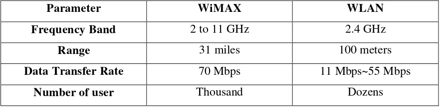
Table 2.1 Comparison between WiMAX and WLAN
Parameter WiMAX WLAN
Frequency Band 2 to 11 GHz 2.4 GHz
Range 31 miles 100 meters
Data Transfer Rate 70 Mbps 11 Mbps~55 Mbps
Number of user Thousand Dozens
The WiMAX standard relies upon a grant-request access protocol that does not allow data collision and therefore, uses the available bandwidth more efficiently. No collision means any loss of bandwidth due to data retransmission. All communication is coordinate by the base station. The main characteristic of the WiMAX standard include;
Long range of service area – the service area of WiMAX standard can be up to 30 miles.
Higher quality of services – the QoS of WiMAX is definitely higher compare to other standard due to no collision protocol.
8
2.2 RF Front End Block Diagram
[image:23.612.115.540.306.495.2]Direct conversion, also known as homodyne or zero-IF conversion, is a natural approach to convert an RF signal directly to baseband. A baseband signal has all the frequencies from 0 Hz to the highest frequency component with significant power. After the frequency it changed for transmission the higher frequency RF signal will have at least double what the baseband signal had initially. Alternately, one can think of choosing IF to be zero. The architecture of the proposed project;
Figure 2.2.1 Front end receiver block diagram. [2]
9
2.3 LNA Design
Microwave Transistor Amplifier is design using the scattered parameters (S parameter). Microwave amplifiers combine active elements with passive transmission line circuits to provide functions critical to microwave systems and instrument. The history of microwave amplifiers begins with electrons device using resonant or slow-wave structures to match slow-wave velocity to electron beam velocity. [3]
The design techniques used for BJT and FET amplifiers employ the full range of concepts that have been developed in the study of microwave transmission lines, two-port network and Smith chart presentation. [4]
The development of S-parameter matrix concepts grew from the need to characterize active devices and amplifiers in a form that recognized the need for matched termination rather than short-or open circuit termination.
![Figure 2.2.1 Front end receiver block diagram. [2]](https://thumb-ap.123doks.com/thumbv2/123dok/636942.77306/23.612.115.540.306.495/figure-end-receiver-block-diagram.webp)
