i
DEVICE for ROAD VEHICLE using WIRELESS TRANSMISSION ROTATING WHEELS
MOHD SYAFIQ ZAIM B AZMAN
This Report Is Submitted In Partial Fulfillment of Requirement for the Bachelor Degree of Electronic Engineering (Telecommunication Electronics) With Honors
Faculty of Electronic and Computer Engineering Universiti Teknikal Malaysia Melaka
ii
UNIVERSTI TEKNIKAL MALAYSIA MELAKA
FAKULTI KEJURUTERAAN ELEKTRONIK DAN KEJURUTERAAN KOMPUTER
BORANG PENGESAHAN STATUS LAPORAN PROJEK SARJANA MUDA II
Tajuk Projek : DEVICE FOR ROAD VEHICLE USING WIRELESS
TRANSMISSION ROTATING WHEEL
Sesi
Pengajian : 2008/2009
Saya MOHD SYAFIQ ZAIM B AZMAN mengaku membenarkan Laporan Projek Sarjana Muda ini disimpan di Perpustakaan dengan syarat-syarat kegunaan seperti berikut:
1. Laporan adalah hakmilik Universiti Teknikal Malaysia Melaka.
2. Perpustakaan dibenarkan membuat salinan untuk tujuan pengajian sahaja.
3. Perpustakaan dibenarkan membuat salinan laporan ini sebagai bahan pertukaran antara institusi pengajian tinggi.
4. Sila tandakan ( √ ) :
SULIT*
(Mengandungi maklumat yang berdarjah keselamatan atau kepentingan Malaysia seperti yang termaktub di dalam AKTA RAHSIA RASMI 1972)
TERHAD* (Mengandungi maklumat terhad yang telah ditentukan
oleh organisasi/badan di mana penyelidikan dijalankan)
TIDAK TERHAD
Disahkan oleh:
_________________________ __________________________________
(TANDATANGAN PENULIS) (COP DAN TANDATANGAN PENYELIA)
Alamat Tetap: LOT 41961 JLN Melati 3 SUNGAI KANTAN, 43000 KAJANG SELANGOR
iii
―I hereby declare that this report is the result of my own work except for quotes as cited
in the references.‖
Signature μ ………
iv
―I hereby declare that I have read this report and in my opinion this report is sufficient
in terms of the scope and quality for the award of Bachelor of Electronic Engineering
(Telecommunication Electronics) With Honors.‖
Signature μ ………
Supervisor‘s Name : MR ZULKIFLI B SHARIFF
v
vi
ACKNOWLEDGEMENT
Big thanks to Allah S.W.T , my parents and all people who get involved or helped a lot in to complete this project.
Thus, the completion of this project would not have been successful without supports, helps and encouragement from various people. Their valuable advice and encouragement had assisted me throughout the completion of this project. First of all, I would like to express my greatest gratitude to my supervisor En Zulkifli B Shariff, who had encouraged, directed, and guided me throughout the entire project with much patience and supportive. His excellent supervision had been the key factor for the success of the Project Sarjana Muda 2 (PSM2). And not forgetting my fellow friends and lecturers who helped me a lot throughout the project.
And for the person that I forgot to mention in this segment, I would like to say a big thank you for you all. Without the support and help that you all gave to me, this project would not be successfully.
vii
ABSTRACT
viii
ABSTRAK
Tujuan projek ini dilaksanakan adalah untuk merekabentuk satu alat untuk mengawasi tekanan angin pada tayar. Pengesan tekanan angin yang terletak pada tayar ini akan mengawasinya secara berterusan. Alat ini mempunyai dua komponen yang penting dimana pengesan tekanan angin di lekatkan pada tayar dan alat tayang berada di dalam kereta (papan pemuka). Pengesan akan mengahantar isyarat dalam bentuk Frequenci Radio (RF) dan ia akan peka terhadap perubahan angin pada tayar. Alat tayang pula akan menayangkan bacaan tekanan angin apabila tekanan angin menurun. Bahagian utama yang berada di dalam pemancar adalah pengesan tekanan angin. Pemancar akan menghantar data-data seperti ID pengesan, tekanan, suhu dan status bateri (jika ada) serta lain-lain maklumat yang berkaitan (jika ada). Data ini telah di
hantar pada ‗Mikro Controller Unit (MCU)‘ atau penerima yang khusus pada satu-satu
ix
TABLE OF CONTENTS
CHAPTER TITLE PAGE
PROJECT TITLE i
REPORT VERIFICATION STATUS FORM ii
DECLARATION iii
SUPERVISOR DECLARATION iv
DEDICATION v
ACKNOWLEDGEMENT vi
ABSTRACT vii
ABSTRAK viii
TABLE OF CONTENTS ix
LIST OF TABLES xiii
LIST OF FIGURES xiv
LIST OF TERMS xvi
LIST OF APPENDICES xvii
I INTRODUCTION 1
1.1 Project introduction 1
1.2 Problem Statement 2
1.3 Project Objective 3
1.4 Project Scope 3
x
1.6 Thesis Overview 5
II LITERATURE REVIEW 6
2.1 What is proper for Tire Pressure ? 7 2.2 Tire Inflation Condition and Maintenance Practice 7
2.3 Types of TPMS 8
2.3.1 Direct 9
2.3.2 Indirect 10
2.4 The TPMS Scheme 12
2.4.1 Tire Pressure Sensor 12 2.4.1.1 Sensonor SP12 14 2.4.1.2 Sensonor SP13 16 2.4.1.3 Freescale MPXY8300 17 2.4.2 Radio Frequency Transmitter and Receiver 19 2.4.3 Circuit Sketch Map and Working Principle 20 2.5 Key issues in the System Development 22
2.5.1 Antenna Design 22
xi
III PROJECT METHODOLOGY 29
3.1 Introduction 29
3.2 Work Flowchart 30
3.3 Research and Finding 31
3.4 System Components 31
3.4.1 Sensor/Transmitter (S/Tx) Device 32
3.4.2 RF Receiver Module 32
3.4.3 LF Commander Device 33
3.4.4 Control Unit 33
3.5 Development Process 33
3.5.1 Calculation 34
3.5.2 Process of Simulation 34 3.5.3 Circuit Installation 34
3.5.3.1 Circuit Layout
(Using Proteus VSM 6.9) 35 3.5.3.1.1 Circuit Construction and
Assembly 36
3.5.3.1.2 Component Parameter
xii
IV RESULT AND DISCUSSION 46
4.1 Product Overview 46
4.1.1 Product Operation 48
4.1.2 Transmitter Circuit 49 4.1.2.1 Sensonor SP-13 Sensor 49 4.1.3 RF Transmission Format 51 4.1.4 LF Transmission Format 53
4.2 Product on Test 54
4.2.1 First Prototype 55
4.2.2 Second Prototype 55
4.3 Discussion 56
4.3.1 Specification of Receiver Unit 57 4.3.2 Specification of Display Unit 57
V CONCLUSION AND SUGGESTION
5.1 Conclusion 58
5.2 Suggestion 59
xiii
LIST OF TABLES
NO TITLE PAGE
2.1 Characteristic of Direct and Indirect TPMS 11
4.1 Bit Function 54
4.2 Receiver Unit Specification 57
xiv
LIST OF FIGURES
NO TITLE PAGE
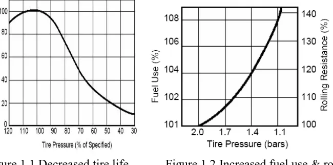
1.1 Decreased Tire Life with Lower Pressure 2
1.1 Increased Fuel use and Rolling Resistance with Lower 2 Pressure
2.1 Sketch Map of the System 12
2.2 Tire Pressure Sensor 13
2.3 SP12 Block Diagram 15
2.4 Mechanical Dimension and Label SP12 15
2.5 Block Diagram of SENSONOR SP13 17
2.6 MPXY8300 Architecture 18
2.7 MPXY8300 Specification 18
2.8 Transmission Circuit 20
2.9 Receiving Circuit 21
2.10 Simulation Model for the Wheel Antenna 24
2.11 Radiation Pattern at 00 25
2.12 Radiation Pattern at 900 25
2.13 Radiation Pattern at 1800 26
2.14 Radiation Pattern 2700 26
3.1 Overall Project Flowchart 30
3.2 ISIS 6 Professional user Interface 35
3.3 Select Component from Library 36
3.4 Edit Component Value 37
3.5 PCB Design in ARES Professional (Proteus 6.9 SP5) 38
xv
3.7 Resistor Value 40
3.8 Polarity Testing 40
3.9 Automatic Etching Machine 41
3.10 Black Box Pressure Pad UV Exposure Unit 41
3.11 PCB Positive Board (Down Side) 42
3.12 PCB Positive Board (Top Side) 42
3.13 Soldering Process 43
3.14 Project Prototype (Front View) 45
3.15 Project Prototype (Side View) 45
4.1 First Prototype 47
4.2 Second Prototype 47
4.3 Pressure Alert 48
4.4 Temperature Alert 48
4.5 Overall Transmitter Circuit 49
4.6 Blog Diagram of Sensonor SP-13 51
4.7 RF Transmission Encoding Method 51
4.8 LF Transmission Encoding Method 53
4.9 First Condition 55
xvi
LIST OF TERMS
ADC - Analog to Digital Converter ASK - Asynchronous Shift Keying CRC - Cyclic Redundancy Check DC - Direct Current
FSK - Frequency Shift Keying IC - Integrated Circuit kPa - kilo Pascal
LCD - Liquid Crystal Display LED - Light Emitting Diode
LF - Low Frequency
LFO - Low Frequency Oscillator LTL - Less than Truck Load MCU - Micro Controller Unit PCB - Printed Circuit Board
PIC - Programmed Integrated Circuit PSI - Pound Square per Inch
RAM - Random Access Memory RF - Radio Frequency
SMD - Surface Mount Device SoC - System on Chip S/Tx - Sensor Transmitter
TL - Truck Load
TPMS - Tire Pressure Monitoring System UHF - Ultra High Frequency
xvii
LIST OF APPENDICES
NO TITLE PAGE
A SP13 Tire Pressure Sensor 62
B N- Channel Enhancement Mode MOS Transistor 67
C 12SMX Crystal 73
D 3V Lithium Battery 75
1
CHAPTER 1
INTRODUCTION
1.1 Project Introduction
This project is to design a device used to monitor the tire pressure and verify an inflated tire. This system continuously monitors the pressure sensors located in the tire. The information collect by the sensors will transmit to on-board processor that interprets the sensor signals and warns the driver when the pressure is below the minimum acceptable level by illuminating a warning lamp or show the value of tire pressure.
This device consists of two basic components which is tire Sensors which screw onto the valve stems of the tires, and a Monitor. The Sensors transmit a coded RF signal
and can alert if pressure drops. The Monitor displays each tire‘s pressure and can send
2
1.2 Problem Statement
Now days, most of accidents on the road were caused by tires. This is because the driver cannot monitor the tire pressure while their driving. Under inflated tires typically result in increased tire wear, decreased vehicle performance, and compromise the ability of the tires to maintain a safe interface with the road. There are some reasons to always properly inflate:
Vehicle Safety - Proper tire inflation greatly reduces the potential of a tire
blowout.
Improved Fuel Economy - Under-inflated tires increase the rolling resistance
of vehicles and, correspondingly, decrease their fuel economy.
Enhanced Vehicle Performance - through proper tire inflation, will allow
optimum performance of vehicle with greater stability.
Increased Tire & Tread Life - When a tire is under-inflated, more pressure is
placed on the tire, causing the tread to wear more rapidly than it would if the tire were inflated to the proper pressure.
[image:19.612.166.491.494.655.2]
3
1.3 Project Objectives
First objective of this project is provides a most accurate pressure monitoring system for safety. It will help the driver to monitor the safe tire pressure while it driving. Second is to monitors for low tire pressures, and high tire pressure and the last objective for this project is provide a indicator to show the location of the problem tire.
1.4 Project Scope
This project will focus on monitoring car tire pressure with wireless transmission system. Only one part of the system will be cover in this project:
4
1.5 Project Methodology
Phase1: Project Planning
Every weeks, meet and discuss with supervisor Mr Zulkifli b Shariff and show the project progress. Get the more information about tire monitoring system from supervisor, internet, books, journal, thesis, and so on. Firstly, I try to understand the concept & desired result for this system. After that, I get the datasheet of component involved (transmitter circuit, sensor, & receiver circuit).
Phase2: Literature Review
For this phase, I will do a survey to the entire previous tire monitoring system project for find the best method and rapprochement to my project. Do literature survey from journal and internet.
Phase3: Hardware Preparation
For this phase, I will find the primary component involved in this system and design the interface circuit. After that, I will Test the functional, ability & weakness. If have some error at the hardware, I will troubleshoot the circuit & redesign the circuit if needed to get better result.
Phase4: Finishing
5
1.6 Thesis Overview
In this part, it will discussed about the summary or overview for each chapter contained in this report. Chapter I will be discussed about the introduction of this project. There are problem statements, objectives of the project, project scope and project methodology. In chapter I also consists the summary of this report.
Chapter II is discussing about literature research and review which contains of introduction of tire pressure monitoring system.
For chapter III, the methodology and development of the project will be discussed. Covering in this chapter are the flowchart of project methodology which will summarize the overall application of the system. The subtopics are also will be cover which are the hardware and software parts.
Result and discussion of the project is covering in chapter IV. All the findings and analysis will be discuss in this chapter to determine whether it has cover the overall objectives of the project.
6
CHAPTER 2
LITERATURE REVIEWS
A vehicle‘s tire performance has a major influence on the performance of the
vehicle‘s three basic functions which is running, turning, and stopping as well as on ride
comfort, noise, and fuel efficiency. To enable the tires to perform to their full potential, it is crucial to maintain the correct tire pressures at all times. However, many drivers continue to drive their vehicles without any awareness of decreased and otherwise inadequate tire pressures. Tire pressure monitoring systems represent a solution that is attracting much interest. At many country especially United State, it will be compulsory for every vehicle to have a tire-pressure monitoring system for better safe.
7
2.1 What is proper for tire pressure?
To check your tire pressure, you need to know what the vehicle‘s manufacturer
recommends. Tire pressure is expressed in pounds per square inch, or psi. Depending on the make of the vehicle, the information can be on the tire placard located on the vehicle door edge, door post, glove-box door or inside the trunk lid [1].
According to John Maxgay, lead engineer, GM Chassis Electronics, when a tire is underinflated, most of the car's weight is concentrated on the tread located just under the sidewalls, rather than being spread out evenly across the full width of the tire. This means that as the tire rolls, the sidewall is continually flexed and could heat up. This may affect both vehicle performance and safety.
On the other hand, while overinflated tires are not associated with as many crashes as underinflated tires, overinflated tires can make the vehicle ride stiff because they do not allow for desired full tread contact (due to the car riding chiefly on just the center of the tread). Overinflated tires also can be more susceptible to being punctured.