DOI: 10.12928/TELKOMNIKA.v13i3.2094 836
Simplified Linear Configuration Model of 3x3 Single
Mode Fiber Coupler using Matrix Transfer
Saktioto*1, Dedi Irawan2, Defrianto3 1
Dept.of Physics, Faculty of Math and Natural Sciences, University of Riau, Indonesia 2
Advanced Photonics Science Institute, Universiti Teknologi Malaysia, Malaysia 3
Dept.of Industial Engineering, Faculty of Science and Technology, Riau, Indonesia *Corresponding author, e-mail: [email protected]
Abstract
Experimental design and operation of a directional fiber coupler having identical-output ratio is successfully fabricated. The coupling region is imposed by fusion temperature 800-1350 0C injecting the Hydrogen gas at 1Atm. Concurrently the coupled-mode theory is used to model power transfer between the waveguides by using transfer matrix method. By 1mW source input power to one of three input ports, it shows that power propagation among three coupled fibers is normalized; the optical fiber are nearly identical and a similar separation between them. The matrix configuration of 3x3 is also used to calculate the polarization effect of directional fiber coupler. It is found that the incident power polarized with various angle causes power output at both three output ports decrease exponentially. This 3x3 directional fiber coupler design is a significant passive component for various functions power splitter and routers.
Keywords: directional fiber coupler, coupled mode theory, power transfer, polarization
Copyright © 2015 Universitas Ahmad Dahlan. All rights reserved.
1. Introduction
Over two decades, the use of optical network in communication system has greatly developed and expanded from a single device to an optical circuit that consists of many components. One of the components, the optical directional fiber coupler is a passive device that is important key as a combiner, divider, splitter, routers and optical switching [1]. Usually a simple directional fiber coupler consists of two fibers coupled having two output ports with typical coupling ratio [2]. Since many optical signal need to be operated and functioned, and a demand to transfer information, more than two fiber couplers are required.
The fiber coupler with three fibers has been weakly joined by heating its coupled region [3]. The problems emerge when the fabrication of coupling ratio cannot be controlled due to different separation between three fibers make different coupling coefficients amongst them. Thus, a full-wave surface integral equation method was used to model rigorous power coupling of 3x3 fiber coupler [4, 5]. This is to establish a power model with a polarized input which being considered for triangular fiber coupler by assuming that power coupling behavior for these normal modes is dominantly decided by the vector fields at the center of fibers.
Because the triangular configuration of coupling region is complicated to maintain during fusion, a simple linear arrangement of three fibers coupled becomes important to be characterized. Therefor in this paper, approach of simple linear configuration of 3x3 directional fiber coupler is fabricated by fusion and elongation method. A normalized coupling power at coupled region is formulated using coupling mode theory by a transfer matrix method. This matrix is also used to examine the performance of fiber coupler in term of polarization effect.
2. Method
mechanical operation is motorized in micrometers scale.
Figure 1. Experimental set up to fabricate SMF coupler
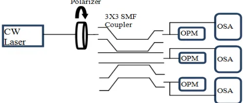
The next set up of fused 3x3 SMF coupler is to design and investigate polarization characteristics as given in Figure 2. Continuous Wave (CW) laser as an optical source is launched to outer fiber (fiber 3) with wavelength operation is 1550 nm. A laser beam is polarized by different angle of polarizer before moving at one of outer fiber (Waveguide 3). An optical Spectrum Analyzer (OSA) and Optical Power Meter (OPM) are set to detect the output.
Figure 2. Measurement of Polarization at the output ports 3x3 SMF coupler
3. Theoretical Consideration of Optical Waveguide Configuration
Figure 3. Ilustration of geometrical fused fiber coupler
(1)
Where , and are power amplitudes in Waveguide (WG) 1, WG 2 and WG 3 respectively. The coupling coefficient is denoted by , and L is coupling length. Since the interaction between the three waveguides occurs from the waveguide 1 to the nearest waveguide, waveguide 2, thus the coupling coefficient of waveguide 1 to waveguide 3,
can be neglected. The eigenvectors of matrix 3x3, can be constructed as:
(2)
And by defining , Equation (1) can be transformed to matrix differential equation:
(3)
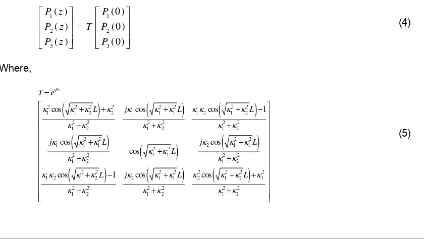
Substituting Equation (1) to will yield a matrix transfer for 3x3 optical directional coupler as follows.
(4)
Where,
(5)
a
P Pb Pc
13
and
31
V
1 1 2 1
2 2 0 2
1 1 2
V
1U V P
1 1
2 2
3 3
2 0 0
( ) ( )
( ) 0 2 0 ( )
( ) 0 ( )
k
U z U z
d
U z j k U z
dz
U z k U z
P V U1 1
2 2
3 3
( ) (0 )
( ) (0 )
( ) (0 )
P z P
P z T P
P z P
2 2 2 2 2 2 2 2
1 1 2 2 1 1 1 1 2 1 2
2 2 2 2 2 2
1 2 1 2 1 2
2 2 2 2
1 1 1 2 1 1
2 2 1 1
2 2 2 2
1 2 1 2
2 2 2 2 2 2 2 2
1 2 1 2 2 1 1 2 1 2 1
2 2 2 2 2 2
1 2 1 2 1 2
cos cos cos 1
cos cos
cos
cos 1 cos cos
i z
T e
L j L L
j L j L
L
L j L L
4. Results and Discussion of Normalized Power Propagation
The propagation of optical power in silica-fiber waveguide coupler described by coupled mode theory shows the strength of the coupling coefficient to transfer power from a waveguide to other waveguide. It significantly depends on separation between fibers axis at coupled region. Since fiber coupler successfully fabricated with waveguides are weakly coupled, the fiber cross section and separation are nearly identical, and power detected at output ports will be normalized. However, the transfer power between the waveguides is various not only each configuration or arrangement of that three fibers joined, but also the optional input port fed by power. In this discussion, linear arrangements of three waveguides at coupling region are purposed.
Power is launched to outer waveguide (WG 1 or WG 3), the power transfer between three waveguides can be determined from matrix transform which is given by (4) in two conditions. The first condition, power is launched in to waveguide 1 or waveguide 3 as a linear
order. By substituting in (4) as shown in Figure 4 will yield,
√ (6a)
√ √ (6b)
√ (6c)
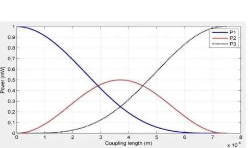
Figure 4. Power transfer between the three waveguides with variable coupling coefficient
Power P1 propagates gradually from initial waveguide (WG 1) to the center waveguide (WG 2). Power P2 affected by the coupling coefficient , will optimize it at waveguide 3 (fiber 3). The second condition, input power is fed in the center of the three waveguides. Similarly, by
substituting in (4), will yield,
(7a)
2
2
0.7769 (1.2252V) (0.0152V )
0.0175 (0.0064V) (0.0009V ) B
C
d d
a
A1(0)1, and A2(0)A3(0)0
23
A2(0)1, and (0)A1 A3(0)0
1 3
1
sin 2 2
j z
(7b)
Figure 5. Power transfer between the three waveguides with variable coupling coefficient
Figure 5 shows that power input will be distributed symmetrically to the two outer waveguide (WG 1 and WG 3) and power P2 is minimum.
5. Result and Discussion of Polarization Effects
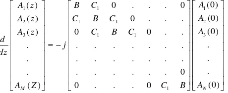
Polarization is a factor that affects the sensitivity and stability of the optical network system, especially for the passive device of fiber optics systems, polarization may cause losses in that device. It is possible to a fiber coupler to have significant losses caused by polarization effects determined from the coupled-mode theory. By rewriting the differential matrix for MXN fiber coupler as (8), where , and are the electric field for the output powers and input powers are respectively:
(8)
Every amplitudes has two component vector polarization, they are x and y component.
Defining is matrix of coupling for single fiber, and is the matrix of
coupling between two adjacent fibers. Where , and are the two polarization
modes, and two -polarization modes, and polarized modes of two adjacent fibers of coupling coefficients respectively.
Consider all fibers are identically isolated and weakly coupled, having different polarization, and the coupling coefficient of this mode is assumed zero. The coupling
coefficients between two identical modes of polarization are assumed and =
= . Equation (1) can be written by Equation (9).
2 cos 2
j z
A z
z e ( )
iA z
A
i(0)
ith1
1 1
2
2 1 1
3
3 1 1
1
(0)
( ) 0 . . . 0
(0)
( ) 0 . . .
(0)
( ) 0 0 . .
.
. . . .
.
. . . .
.
. . . 0
(0)
( ) 0 . . . 0 N
M
A
A z B C
A
A z C B C
A
A z C B C
d
j dz
A
A Z C B
x xy
xy y
B
1
ixjx ixjy
ixjy iyjy
C
ixjx
iyjy ixjyx
y
x
and
y
ixjy
ixjx
xx iyjy yy
xxyy
(9)
Or, it can be simplified in term of transpose matrix describing the matrix transmission of the MXN fiber coupler including the two polarized modes.
(10)
The polarization characteristics of single mode fiber coupler can be investigated by applying matrix (1), then inserting the boundary condition to the calculation. In this research, the polarization characteristics of 3x3 are purposed to be investigated.To examine the polarization behavior of fiber coupler, three fibers are simplified in linear arrangement.
Consider the coupling coefficient given by (5) is held to be constant along the fiber, and
the coupling region is very short, it can be assumed , , and
. By using matrix equation of polarization of multiport fiber
coupler given by (9), Equation (5) becomes:
(11)
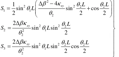
The Equation (11) depends upon the optional input power which is launched. For example, if the input power to the center (fiber 2), the output power at fiber 1 and fiber 3 are given by the following Equation.
1 1 2 2 3 3
1 1 2 2 3 3
. . .
. . .
t
x y x y x y Mx My
t
x y x y x y Mx My
E E E E E E E E z
T E E E E E E E E
1
2
x
y2 2 2
2
2
4
x x y y xy
1 2 3
2
2 4 2
3 2 1
x y
i L
M M M
T e M M M
M M M
2 2 2
1 1
2 2
1 *
2 2 2
1 1
2 2
2 2 2
1 1
2 2
2
1
cos 1 cos sin sin cos 1
2 2 2 2
1
sin cos 1 cos 1 cos sin
2 2 2 2
2 2
sin sin cos sin sin
2 2 2 2
xy
xy
xy
i
L L L
L i L
M
i L L L
L L i
L L L
L i L
M *
2 2 2
1 1
2 2
2 2 2
1 1
2 2
3
2 2 2
1 1
2 2
2 2
sin sin sin sin cos
2 2 2 2
1
cos 1 cos sin sin cos 1
2 2 2 2
1
sin cos 1 cos 1 cos sin
2 2 2 2
xy
xy
xy
L L L
L L i
i
L L L
L i L
M
i L L L
L L i
*
2 2 2
1 1
2 2
4 *
2 2 2
1 1
2 2
2 2
sin sin cos sin sin
2 2 2 2
2 2
sin sin sin sin cos
2 2 2 2
xy
xy
L L L
L i L
M
L L L
L L i
2
2 2 2 2
1 1
2
2 2 2
2 2 1
2
2 2 2 2
3 2 1
2
4 1
sin sin cos
2 2 2
2
sin sin 2 2
sin sin cos
2 2
xy
xy
xy
L L
S L
L
S L
L L
S L
(12
Figure 6 shows good agreement among output power in both three output ports decreases exponentially by increasing the angle of polarization in (12). However, initial power at P1 is slightly higher than that of power at P2 and P3. This is a weakness of 3x3 as a power splitter since the coupled region is linear arrangement. P2 and P3 are held identical and similar power.
Figure 6. Decreasing of output powers versus different angle of polarization
6. Conclusion
Design and operation of numerical experiment of power propagation in 3x3 fiber coupler using coupled mode theory shows that output power in both three ports are normalized. It is classified that the characteristics of output power depend on which waveguide launched by laser beam. The design of 3x3 directional fiber coupler can be used as a routers when the laser beam fed to the waveguide 1, and it is promising good power divider if input power feeds to the waveguide 2 or center waveguides of linear 3x3 fiber coupler. However, polarization correction needs to be considered for the decreasing of output power caused by increasing angle of polarization.
Acknowledgements
We would like to thank to Physics Department, Faculty of Math and Natural Sciences, University of Riau, Pekanbaru, Indonesia, Directorate General of Higher Education, Ministry of Education, Indonesia, theInstitute of Advanced Photonic Science, Faculty of Science, Universiti Teknologi Malaysia, Malaysia, Faculty of Science and Technology, Universitas Islam Negeri SUSKA Pekanbaru, Indonesia for generous support in this research.
References
[1] Alan W. Optical Waveguide Theory. London: Snyder and Jhon D. Love. 1983.
[2] Chin-Lin Chen. Foundations For Guided-Wave Optics. West Lafayette, Indiana: Perdue University. 2007.
Lightwave Technology. 1992; 10(6).
[7] Chin-Lin Chen, William K BURNS. Polarization Characteristics of Single-Mode Fiber Couplers. Journal of Microwave and Techniques. 1982; 30(10).