Precast C-Channel using Oil Palm Shell (OPS) Concrete as
The need to provide affordable housing to ever-growing population nowadays has been continuously in great demand. In Malaysia, there have been frequent emphasises and allocations to provide sufficient housing from the Malaysian Plan to another. The more housing to be provided, the more concrete as one of the main building materials is inevitably to be used directly causing serious depletion of non-renewable natural stones in the concrete production. Tapping on the oil palm industry which has grown in a rapid pace over the past 20 years, using the oil palm shell (OPS) as one of the by-products for construction industry is a sustainable approach. Malaysia being one of the largest oil palm producers in the world generates more than 4 million tonnes of OPS annually, from which about 1.5 million tonnes come from Sabah. The OPS is used as aggregate in concrete production forming OPS concrete which is lightweight and its engineering properties fulfil the requirement as a lightweight concrete. In a typical building made with concrete, floor slab being the largest element compared to other structural members consumes up to 44% of concrete volume. Due to the low elasticity of OPS concrete, conventional crushed granite was added to OPS concrete mix, as 30% replacement to OPS, to produce concrete known as OPS hybrid concrete to fabricate structural floor panels. This paper discusses the performance of precast concrete floor panel namely C-Channel made with oil palm shell (OPS) concrete with regards to construction tolerances, stacking, and erecting. The result of the water leaking tests revealed that C-Channel floor panels can act monolithically under load application.
Keywords: C-channel; construction tolerances, Oil Palm Shell (OPS); precast floor; stacking
INTRODUCTION
The need to provide affordable housing to ever-growing population nowadays has been continuously in great demand. In Malaysia, there have been frequent emphasises and allocations to provide sufficient housing from the Malaysian Plan to another. Residential property prices have been, however, accelerating since 2009 (The Star Online, 28 August 2013). To overcome the issue of rising property, the Government has launched two schemes to make houses affordable, namely the Malaysia My First Home Scheme as introduced in 2011, and the 1 Malaysia Housing Programme which has come into effect in 2012. Nevertheless, very often the price remains far too high beyond the affordability of the low or even middle income group not counting the rural folks and those who stay at the estates. Particularly in Sabah, resettlement of illegal squatters is necessary as they pose security, environment and health pollution risk (The Borneo Post, 16 August 2013).
The more housing to be provided, the more concrete as one of the main building materials is inevitably to be used directly causing serious depletion of non-renewable natural stones in the concrete production. It must be noted that nearly 80 per cent of the resources used today in construction industry are non-renewable. In Sabah alone, the annual aggregate usage has reached about 12 million tonnes. Thus, renewable sources of aggregates are very much needed as alternative to provide a proper building system.
Where high-strength concrete is not required, structural LWC can be used in the design of floor slabs in building and other structural members (Hassoun, 2002). OPS LWC can be a good alternative. Due to the low modulus of elasticity of OPS concrete, however, conventional crushed granite was added to OPS concrete mix, as 30% replacement to OPS, to produce concrete known as OPS hybrid concrete chiefly used in precast flooring slabs fabrication. The optimum percentage of granite used was derived through trial mixes (Ng et al., 2006).
In a typical modern building made of reinforced concrete, the conventional concrete floor slab system consumes the highest concrete volume up to 44% compared to other structural components. The floor construction is the most time-consuming and costly activity particularly for a framed building, representing some 60%-80% of the total in both cost and time (Goodchild, 1997; Matthew and Bennett, 1990). The floor slabs can be made of in-situ reinforced concrete or precast concrete. In the present, there are many types of precast concrete floors available in the markets such as flat slab, rib and timber infill floor, hollowcore, single-T, double-T, beam and blocks, semi-precast slab, and channel slab. Each of these precast products has its own advantages and disadvantages. Generally, they are heavy in weight being made with normal weight concrete (NWC), and also, they require cast in-situ concrete topping which increase the cost of overall production. Prestressed elements which require jacking system is very costly. Therefore, the proper selection of more efficient materials and improved design is essentially required to reduce the cost of precast floor production.
The Government has also started taking initiative years ago to promote sustainable construction of modular elements through precast technology to minimize wastage of building materials at the construction site. It must be noted that though precast technology is no longer foreign to growing developers or big contractors for its proven work quality and achievements within a shorter construction period of time, small and medium contractors would, however, still prefer conventional construction method due to lack of initial capital and exposure. Scarcity of aggregates and increasing building material costs are among two common factors which have somehow discouraged them to venture further.
This paper presents the performance of the precast concrete floor panels namely C-Channels made with OPS concrete with regards to construction tolerances, stacking, and erecting. The result of the water leaking tests revealed that C-Channel floor panels can act monolithically under load application.
2. MATERIALS
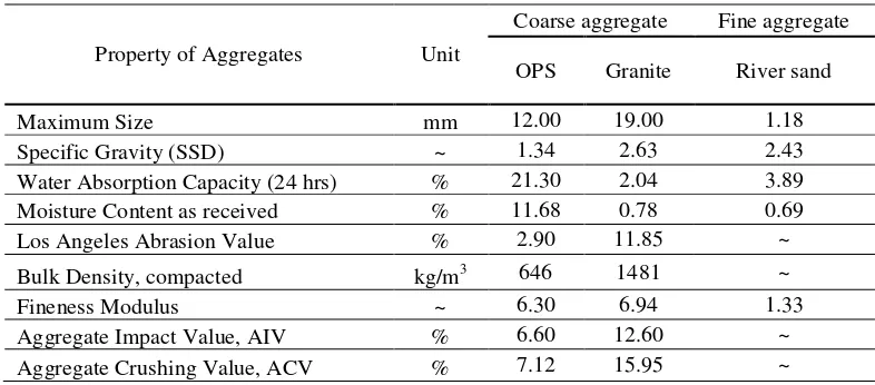
The ordinary Portland cement of ASTM Type I, river sand, OPS and crushed granite have been used. The OPS aggregates have been obtained from Desa Talisai Palm Oil mill, IJM Plantations, Sandakan, Sabah. The properties of OPS, granite and river sand are shown in Table 1, where the aggregate was tested according to BS or ASTM. Table 2 shows the mix proportions of OPS hybrid concrete (as investigated by Ng et al., 2007), was used to cast the C-channel floor panels. The content of cement, water and river sand are kept constant. Free water/ cement (w/c) ratio is 0.38. OPS aggregate used is in saturated surface dry condition. Type-F naphthalene sulphonate formaldehyde condensed based super plasticizer in aqueous form conforming to ASTM C 494 has been used to increase the workability.
Table 1. Properties of OPS, crushed granite and river sand
Table 2. Constituents of 1.0 m3 OPS hybrid concrete
Constituent Unit Quantity
Cement kg 450
Water kg 171
River Sand kg 629
OPS kg 341
Crushed granite kg 313
Super plasticizer liter 7.5
3. METHODOLOGY
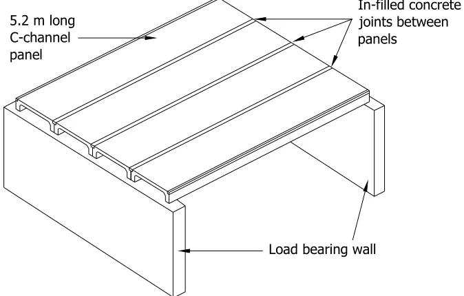
Four nos of prototype C-channels were cast using OPS hybrid concrete into special steel-timber mould and cured for 7 days through water-spraying. After which, they were transported prior to stacking and erecting to form the full-scale monolithic floor (see Figure 1). The properties of C-channel designated as CH-1, CH-2, CH-3, and CH-4 used are presented in Table 3. The total length of the C-channels is 5.2 m with the total rib depth 240 mm. The cross-section area was 0.106 m2 which consumed concrete volume up to 0.551 m3 per panel.
Table 3: Panel properties of C-channels
Properties per panel Panels
(CH-1, CH-2, CH-3 and CH-4)
Total length (m) 5.2
Total rib depth (mm) 240
Cross section area (m2) 0.106
Total concrete volume (m3) 0.551
Total weight (kg) 1,102
Modulus of elasticity of concrete, EC (MPa) 16,280
The four nos of C-channels were carefully transported to a location near the construction site where the lorry crane can erect the panels within reach and without the need of multiple handling.
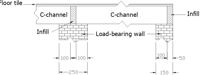
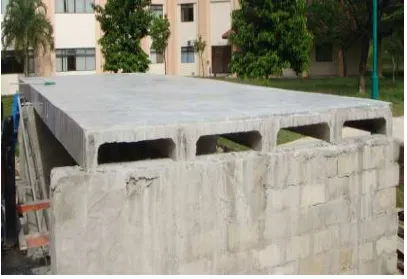
These C-channels were placed side by side next to one another to form a flooring structure with a total area of approximately 21 m2 supported by load-bearing walls made with solid concrete blocks. Each C-channel comes with two-edged grooves for the purpose of connection between panels when set up as floor structure. The groove of two individual panels when placed together forms a longitudinal joint which is to be filled with mortar as shown in Figure 2. It must be noted that the mortar infill was only needed for in-situ casting of joints between panel and panel.
Figure 2: Support details of C-channels on load-bearing walls
The design and construction of joints is the most critical consideration in precast concrete construction. Seven days after infilling the joints between C-channels, testing was conducted to investigate the jointing integrity using uniform distributed load and water ponding. The compressive strength of the companion cubes of the in-situ mortar infill was approximately 22.7 MPa at the age of 7-day.
4. RESULTS AND DISCUSSIONS
As soon as the panels were erected onto their respective final positions on the load-bearing walls, the jointing work could begin immediately. Prior to finishing work, the lifting “eyes” protruding out of C-channel top surface were cut off, which have been done easily at the site. It is also worth to note that the thin section of the flange can significantly reduce the drying time of the concrete prior to applying floor coverings (West and Holmes, 2005).
4.1Construction Tolerances
For concrete floor and slab construction, the construction tolerances such as forms, slab thickness, floor flatness are to be looked into (ACI 302). Based on Ballast (2007) and Precast/ Prestressed Concrete Institute (2000), product tolerances must be coordinated with erection tolerances and tolerances for other building systems for a successful project. For cored slabs used for floor construction, the maximum tolerance form both plan and elevation end squareness (Esq) is 13 mm. The tolerance for length (L) and width (a and b) is
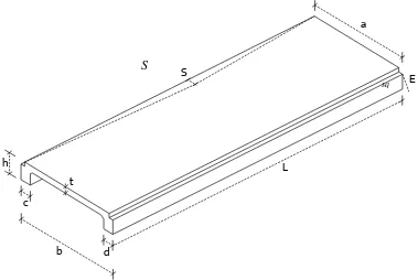
13 and 6 mm respectively. 10 mm is allowed for the sweep (S). The tolerance for the tipping and flushness of plates is 6 mm. Tolerances for bearing length and bearing width (c and d) is 19 and 13 mm respectively. The notation of tolerances for C-channel is shown in Figure 3.
Figure 3: Notation of construction tolerances for C-channel
Table 4: Construction tolerances for C-channels
Panel L (mm) a (mm) b (mm) c (mm) d (mm) t (mm) h (mm) S (mm) Esq
(mm)
CH-1 5,210 1,000 1,000 100 105 75 245 10 2
CH-2 5,205 1,005 1,005 100 100 75 240 5 1
CH-3 5,205 1,005 1,000 100 100 75 245 5 2
CH-4 5,210 1,000 1,000 105 100 75 240 5 0
The minimum bearing width i.e. 90 mm. Adequate support of precast concrete floor units is one of the most basic requirements for a safe structure. The total length of panels, L was found to be more than 5 m (Table 4) giving extra positive tolerances for the bearing widths. Elliott (1996) has pointed out that the minimum bearing widths are achieved because flooring units are manufactured to positive tolerances. In addition, BS 8110 has stated that the net bearing width of a member, that is free to move relative to a support, should be increased to allow for any likely movement. According to Cement Concrete & Aggregates Australia (2003), the end bearing width varies with panel thickness. Table 5 presents the minimum bearing for precast floor panels.
Table 5: Minimum bearing for precast floor panels
Panel thickness (mm) Minimum bearing on concrete (mm)
150 and 200 80
250 and 300 120
For joint tolerances, joints are sized to allow for building movement as well as to accommodate product and erection tolerances. Further to that, joints between precast elements also have their own tolerance. These joints may be about 6 mm in width (Warner, 2004). However, the gap between panels was found in the range of 3 – 10 mm. Nevertheless, relative small tolerances may need to be worked within for better joining (Park, 2003).
4.2 Stacking
The purpose of stacking precast units is to mainly minimize storage space, either at the manufacturing plants or construction site during their transit between demoulding, transporting and erection to their final
S
position. To avoid the precast components from experiencing stress which has not been catered for in the design, the manner how the units are stacked should be done properly.
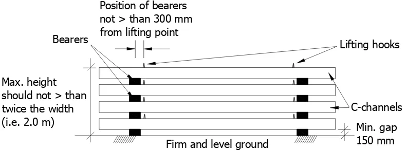
Bearers, in vertical alignments, are to be placed along the length of the precast panels (Elliott, 1996). The positions of such bearers should be within 300 mm from the lifting points as shown in Figure 4. Furthermore, more than two supports points should not be used.
In addition to the precautions to be observed when stacking, care must be taken to ensure that the ground or surface on which the components are to be stacked is suitable. The ground must be firm and level, and wherever possible stacking of components should be on firm hard-core or oversite concrete. The height to which components can be safely stacked on site will be greatly influenced by the condition of the ground on which they bear. Another prime consideration should be the height to which a man can reach to pass lifting chains or slings around the components (Precast Flooring Federation, 2007). During stacking for storage, polythene can be used to wrap precast elements as a form of protection against stain and damages. For precaution at the support end, polystyrene can be used to minimize damages. The Occupational Safety and Health Service (2002) pointed out that incorrect stacking can also cause long-term creep to precast elements.
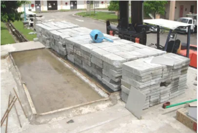
Figure 5 shows the four units of 5.2 m long C-channels made with LWC-2 stacked in vertical alignment with concrete blocks used as bearers. The total height of stacking was approximately 1.56 m from the ground level, which is less than that of the recommendation given by WorkSafe Victoria (2002) that the staked height must not be more than twice the width of the panels i.e. 2.0 m. Prior to erection, careful inspection on the lateral surfaces of all the C-channels indicated that there was no crack developed near or at the bearer position or along the span. There was also no chip-off at the rib edges caused by the hard bearers at the supports. It shows that C-channels can be stacked similarly like any other precast floor products.
! "##
$
% &
' ( # ' )
& !
* # +
Figure 5: Four units of 5.2 m long C-channels in stacked
4.3 Erecting
Since the flange and rib of C-channel is only of 75 mm and 100 mm thick respectively, it does not give a psychological impression of looking massive both in size and appearance.
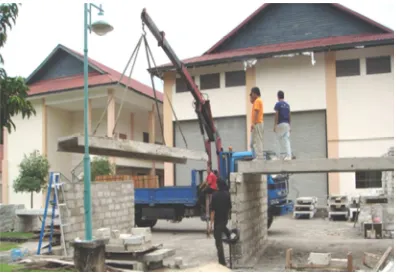
C-channel was made with OPS hybrid concrete which was very much lighter compared to that of NWC, the erection has been done easily and quickly using lorry mounted crane as shown in Figure 6. This is vital as simple erection can considerably reduce the cost of construction (Burachat and Pichai, 1995). Also, the four-point lifting has enabled the C-channels to be effectively and accurately placed at the final positions, due to their practical configuration of side-by-side and end-to-end placement. The complete C-channel floor structure together with tile finishing is shown in Figure 7.
Figure 7: Completed C-channel floor structure with tile finishing
4.4 Water Ponding
The purpose of water ponding test is to investigate the possibility of water leakage at the joint connection between panel to panel. According to Hoglund (2007), water test can be performed to establish joint leakage, as ponding increases the potential and frequency of water leaks. It must be noted that the volume of water ponding was not measured throughout the test duration as the water could be absorbed by the concrete, and the test itself was performed under the weather exposure.
Prior to water ponding, close visual inspection on the joint surface between precast concrete and in-situ mortar infill at the groove showed that there was no sign of crack observed due to differential shrinkage. Relative shrinkage differences between the concrete and the in-situ mortar can cause tensile stresses along the interface, which will result in cracking and leaking of water. Therefore, this visual examination was to ensure that the water would not leak through shrinkage cracks (if there is any) before subjecting to the uniform distributed load. Nevertheless, Hassoun and Al-Manaseer (2005) have stated that shrinkage cracks are significant cracks, as they affect the pattern of cracking produced by applied loads in flexural members. They have further added that shrinkage cracks are difficult to control.
Figure 8: Water ponding with approximate 50 mm deep of water
Figure 9: A total load of 10.15 kN/m2 being placed onto one panel of 5 m x 1 m area
5. CONCLUSIONS
The following conclusions were also made:
(i) The production of C-channels was within the construction tolerances, showing that the steel-timber mould can be used. It can significantly reduce the initial cost of fabricating precast C-channels which is beneficial to small and medium entrepreneurs.
(ii) The C-channels can be stacked up to four units in vertical alignment similarly like other precast floor products.
(iii) C-channel was made with OPS hybrid concrete which was very much lighter compared to that of NWC, the erection has been done easily and quickly using lorry mounted crane. Also, the four-point lifting has enabled the C-channels to be effectively and accurately placed at the final positions, due to their practical configuration of side-by-side and end-to-end placement.
(iv) No sign of water leaking or dripping was found underside of the C-channel ribs throughout the water ponding test verifying the joint integrity and properties. Nevertheless, extended studies are needed to investigate the long-term influence of creep with respect to its effects on joints and colleagues and staff for their help in carrying out the project. Sincere thanks to Dr. Zuhairi Abd Hamid, Mr. Ahmad Hazim Abdul Rahman, Mr. Suhaili Muhamad Shukor and Mr. Demeion Vincent of CIDB, Mr. Lou Chi Nam of Institution of Engineers Malaysia (Sabah Branch), Mr. Chen Kheng Seong and Mr. Paul Pawood of Manax Corporation, Mr. Yong Ming Cheong of Architect Association Malaysia (Sabah Branch), ACPI, BINA PURI, SHAREDA and SUDC for their continuous constructive criticisms. They also express thanks to IJM Plantations for providing OPS aggregate.
REFERENCES
ACI 302. 2004. Guide for Concrete Floor and Slab Construction (ACI 302.1R-04). ACI Manual of Concrete Practice. Detroit: American Concrete Institute.
Aljuboori, A. H. R. 2013. Oil Palm Biomass Residue in Malaysia: Availability and Sustainability, International Journal of Biomass and Renewables, 2(1): 13 – 18.
ASTM, C 494, Standard Specification for Chemical Admixtures for Concrete, Annual Book of ASTM Standards.
Ballast, D. K. 2007. Handbook of Construction Tolerances. (2nd edition). New Jersey: John Wiley & Sons, Inc.
Burahcat, C. and Pichai, N. 1995. Influence of Support Continuity on the Structural Performance of Prefabricated Floor Slabs, Journal of National Research Council Thailand. 27(1):57 – 72.
Cement Concrete and Aggregates Australia. 2003. Guide to Residential Floors (2nd edition). Sydney: Cement Concrete and Aggregates Australia.
Elliott, K. S. 1996. Multi-storey Precast Concrete Framed Structures. London: Blackwell Science Ltd. ENV 1994-1-1. 2004. Eurocode 4: Design of Composite Steel and Concrete Structures – Part 1-1: General
Rules and Rules for Buildings, European Committee for Standardization.
Goodchild, C. H. (1997) Economic Concrete Frame Elements. UK: British Cement Association. Hassoun, M. N. 2002. Structural Concrete: Theory and Design. New Jersey: Prentice-Hall, Inc.
Hassoun, M. N. and Al-Manaseer, A. 2005. Structural Concrete: Theory and Design. (3rd edition). New Jersey: John Wiley & Sons, Inc.
Hoglund, M. 2007. Precast Concrete Façade Investigation. Concrete Repair Bulletin July/August 2007, pp 24 – 25.
Matthew, P. W. and Bennett, D. H. (1990) Economic Long Span Concrete Floors. UK: British Cement Association.
and UWM Center for By-Products Utilization International Conference on Sustainable Construction Materials and Technologies, 11 – 13 June 2007, UK.
Ng, C. H., Kurian, V. J., Narayanan, S. P. and Mannan, M.A. (2006) Mix Design of Precast Concrete Slab Using Oil Palm Shell (OPS) as Coarse Aggregate, 2nd Southeast Asian Natural Resources and Environmental Management Conference, 21 – 23 November 2006, Kota Kinabalu, Sabah, Malaysia.
Park, R. 2003. The Fib State-of-the-art Report on the Seismic Design of Precast Concrete Building Structures, 2003 Pacific Conference on Earthquake Engineering, Paper No. 011.
Precast Flooring Federation. 2007. Code of Practice: For the Safe Erection of Precast Concrete Flooring and Associated Components. Leicester: Precast Flooring Federation.
Precast/ Prestressed Concrete Institute. 2000. Tolerance Manual for Precast and Prestressed Concrete Construction. Illinois: Precast/ Prestressed Concrete Institute.
The Borneo Post, 2013. “Sandakan Council t obuild low-cost houses”. 16 August 2013.
The Occupational Safety and Health Service. 2002. Approved Code of Practice for The Safe Handling, Transportation and Erection of Precast Concrete. Wellington, New Zealand.
The Star Online, 2013. “No immediate bubble risk for Malaysia’s property sector”, 28 August 2013.
Warner, J. 2004. Practical Handbook of Grouting: Soil, Rock and Structures. New Jersey: John Wiley & Sons. Inc.
West, R. P. and Holmes, N. 2005. Predicting Moisture Movement During the Drying of Concrete Floors Using Finite Elements, Construction and Building Materials. 19:674 – 681.
WorkSafe Victoria. 2002. Checklist for the Manufacturing of Precast Concrete Panels.