SUPERVISOR DECLARATION
“I hereby declare that I have read this thesis and in my opinion this report is sufficient in terms of scope and quality for the award of the degree of
Bachelor of Mechanical Engineering (Automotive)”
EFFECT OF YAW ANGLE ON THE AERODYNAMICS PERFORMANCE OF REAR SPOILER – BY CFD STUDY
TEE JIA WEI
This thesis is submitted to Faculty of Mechanical Engineering as a requirements to get award of
Degree of Mechanical Engineering (Automotive)
Faculty of Mechanical Engineering Universiti Teknikal Malaysia Melaka
ii
DECLARATION
“I hereby declare that the work in this report is my own except for summaries and quotations which have been duly acknowledged.‟
Signature: ... Author: TEE JIA WEI
iii
ACKNOWLEDGEMENTS
Here, I would like to acknowledge all those people who help and guided me throughout the completion of this project.
This project would not be completed without the help of my supervisor, Dr. Cheng, who guide and help me throughout the progress. I would like to express my deepest gratitude to him for his patience to help me improve this project. Furthermore, Dr. Cheng also aside his valuable time to monitor our progress every week, in which we have a weekly meeting for all of the students under his supervision to present our progress throughout the week. As a result, we manage to keep up with our Gantt chart progress. By his leadership and supervision, we managed to keep on the right track to do research and finish our PSM on time.
iv
ABSTRACT
v
ABSTRAK
vi
TABLE OF CONTENTS
CHAPTER TITLE PAGE
DECLARATION ii
ACKNOWLEDGEMENT iii
ABSTRACT iv
ABSTRAK v
CONTENT iv
LIST OF FIGURES viii
LIST OF TABLE x
LIST OF SYMBOLS xi
LIST OF ABBREVIATION xii
CHAPTER 1 INTRODUCTION 1
1.1 BACKGROUND 1
1.2 PROBLEM STATEMENT 2
1.3 OBJECTIVE 3
1.4 SCOPE 3
CHAPTER 2 LITERATURE REVIEW 4
2.1 AERODYNAMIC OF ROAD VEHICLE 4
2.2 AERODYNAMIC PERFORMANCE 5
2.2.1 Drag 5
2.2.1.1 Drag reduction 6
2.2.2 Lift and Pitch Moment 7
2.2.3 Side Force and Yaw Moment 8
2.2.4 Yawing Stability 9
vii
2.3.1 Rear Spoiler 12
2.3.1.1 Roof Spoiler 13
CHAPTER 3 METHODOLOGY 14
3.1 SOFTWARE 14
3.2 HARDWARE 14
3.3 MODEL CONFIGURATION 15
3.4 NUMERICAL SETTING 18
3.4.1 Physical Condition and Initial Condition 18
3.4.2 Solution Algorithm 19
3.4.3 Boundary Condition 19
3.5 COMPUTATIONAL DOMAIN 20
3.6 MESH 21
CHAPTER 4 RESULTS AND DISCUSSION 25
4.1 CONVERGENCE OF SIMULATION RESULT 25
4.2 Y PLUS 26
4.3 COMPARISON OF SIMULATION RESULT 27 4.4 COMPARISON OF AERODYNAMIC
COEFFICIENT
30
4.4.1 Comparison of Drag Coefficient (CD) 30
4.4.2 Comparison of Lift Coefficient (CL) 38
4.4.3 Comparison of Yaw Moment Coefficient (CYM)
40
4.4 .4 Comparison of Pitch Moment Coefficient (CPM)
42
CHAPTER 5 CONCLUSION AND RECOMMENDATION 46
5.1 CONCLUSION 46
5.2 RECOMMENDATION 47
REFERENCES 48
viii
LIST OF FIGURES
FIGURE TITLE PAGE
2.1 Forces and moments axes of a vehicle 4
2.2 „Squareback‟ large scale flow separation 6
2.3 „Hatchback/Fastback‟ vortex generation 6
2.4 Influence of backlight angle on drag coefficient 7 2.5 Yaw moment and side force coefficients for a family of
cars with different rear end shapes
8
2.6 Body axis drag at nonzero yaw angle 10
2.7 Pressure distribution of for a moving car 12
2.8 Positioning of a rear spoiler 13
3.1a Top view 16
3.1b Side view 16
3.2 Ahmed model with a rear spoiler depicting the slant length (L) and radius of curvature (R)
17
3.3 Ahmed model with single slot rear spoiler (isometric view) 17 3.4 Ahmed model with double slot rear spoiler (isometric
view)
18
3.5 Dimension of computational domain 21
3.6 Face sizing control for Ahmed model 35 degrees slant 22 3.7 Recommendation for prisms layer growth on the vehicle
surfaces
22
3.8 Prism layer 23
3.9 Overview of the whole domain mesh 24
4.1 Drag Coefficient (CD) convergence of the base model 25
4.2 Y plus value contour for model without spoiler 26
4.3 Static pressure contours comparison 28
4.4 Velocity streamlines comparison 29
ix
4.6 Pressure distribution comparisons between 0° and 30° yaw angle; contour plane at 0.5H
31
4.7 Percentage distribution of drag coefficient 32 4.8 Pressure contour of the surface of base model 32 4.9 Pressure contour comparison of the surface of base model 33 4.10 Comparison of windward side pressure at 15° and 30° yaw
angle
33
4.11 Comparison of leeward side pressure at 15° and 30° yaw angle
34
4.12 Velocity streamline comparison for 15° and 30° yaw angle; plane at 0.5H
35
4.13 Percentage difference of drag coefficient compared to model without spoiler (base model)
36
4.14 Lift coefficient (CL) comparisons 38
4.15 Section parts model 38
4.16 Percentage difference of lift coefficient compared to model without spoiler (base model)
39
4.17 Center of pressure location 40
4.18 Yaw moment coefficient (CYM) comparisons 40
4.19 Percentage difference of yaw moment coefficient compared to model without spoiler (base model)
41
4.20 Pitch moment coefficient (CPM) comparisons 42
4.21 Percentage difference of pitch moment coefficient compared to model without spoiler (base model)
43
4.22 Pressure contour on the top surface of model without spoiler
44
4.23 Pressure contour on the bottom surface of model without spoiler
x
LIST OF TABLES
TABLE TITLE PAGE
3.1 Characteristic of simplified car model with and without spoiler
15
3.2 Simulation case 15
3.3 Parameters of model 16
3.4 Physical condition for fluid 18
3.5 Initial condition for fluid 18
3.6 Solver setting 19
3.7 Viscous Model and Turbulence Model Settings 20
3.8 Boundary Condition Settings 20
3.9 Number of elements and nodes 23
4.1 Y plus value 26
4.2 Drag coefficient comparison at 0° yaw angle (numerical and experimental)
36
4.3 Drag coefficient comparison at 30° yaw angle (numerical and experimental)
37
xi
LIST OF SYMBOLS
V = velocity
Re = Reynolds Number
F = force
M = moment
A = reference area
l = reference length
= density
f
C = force coefficient
m
C = moment coefficient
d
C = drag coefficient
l
C = lift coefficient
= yaw angle
K = turbulent kinetic energy
slant
L = slant length
R = radius of curvature
Pa = pascal
L = length of model
xii
LIST OF ABBREVIATION
1
CHAPTER 1
INTRODUCTION
1.1 BACKGROUND
2
1.2 PROBLEM STATEMENT
A high speed travelling vehicle will become unstable due to the effect of lift (Karnoop, 2013). Under normal condition, vertical force on a bluff body is positive and it tends to lift the vehicle. The decrease in rear wheel load as a result of Bernoulli's effect will increase the sensitivity of steering response to small disturbance, thus making the vehicle unstable as such over steer might occur. Rear spoiler mounted on the trunk of a car can alter the air stream at the rear body. Thus, supply under pressure for a vehicle, increase the body down force. Hence, lift is reduced (Tao, 2011). There is always an ambient wind and the wind is not aligned with the road along which vehicle is travelling causes the vehicle to operate at a yaw angle (Hucho & Sovran, 1993). Under yaw condition, yawing moment is significant. Yawing moment tends to force vehicle further away from the direction of wind and thus making the vehicle unstable.
3
1.3 OBJECTIVE
The purpose of this research is to study the effect of yaw angle to the aerodynamic performance of the rear spoiler. The objectives of this research are:
1 To investigate the effect of yaw angle on the aerodynamic performance of the hatchback car with various spoiler configuration
2 To perform CFD simulation of hatchback car model flow using ANSYS fluent
3 To validate the CFD simulation results
1.4 SCOPE
The car model used in this study is a hatchback type car. Ahmed model with 35 degree slant angle at the rear is used to represent the hatchback type car. It will be placed in room temperature condition under the yaw angle of 0, 15, and 30 degrees respectively with the air velocity,V of 30 m/s. The corresponding Reynolds number,
Re based on vehicle length is 3.28x10⁵. Four cases will be tested accordingly. First,
4
CHAPTER 2
LITERATURE REVIEW
2.1 AERODYNAMIC OF ROAD VEHICLE
The study of aerodynamics in vehicles has been focused on drag reduction due to fuel crisis of the early 1970s. However, the concern has been shifted to lift and side force in the recent year due to the importance of vehicle stability in the modern vehicle design. The vehicle stability is reduced in a crosswind situation as a result of the side effect caused by low drag shapes developed during the early 1980s. However, the concern on vehicle stability in crosswind has been considered by designers (Dominy, 2002).
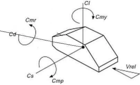
[image:17.595.180.447.578.740.2]Generally, there is a total of six basic forces and moments that acts on a vehicle body which comprises of three forces and three moments. Figure 2.1 shows the forces and moments axes of a vehicle.
5
The force and moment coefficient are defined in Eq. (2.1) & (2.2) :
A F Cf 2 2 1 (2.1) Al M Cm 2 2 1 (2.2)
Where F is force (lift, drag, and side), M is moment, is air density, is velocity,
A is reference area and l is reference length. The reference area is usually referred to frontal area in vehicle aerodynamic.
2.2 AERODYNAMIC PERFORMANCE 2.2.1 Drag
Drag is the force that a flowing fluid exerts on a body in the flow direction. Drag is normally undesirable. Reduction of drag often closed related to the reduction of fuel consumption in automobiles; improve stability and durability; and reduction of noise and vibration. There are a few factors that influence drag force. Density of fluid p, upstream velocity v, size, shape and orientation of the body are the main
factors that affect the drag force of a body. Dimensionless number, drag coefficient
d
C is used to represent drag characteristic of a body. Streamline body has a lower
d
C compared to blunt body when moving at the same speed through a fluid (Cengel & Cimbala, 2006).
6
2.2.1.1 Drag Reduction
The drag creation of a vehicle is closely related to the aerodynamic noise. The reduction of drag has directly reduced the aerodynamic noise with mutual benefits. However, this mutual benefit does not contribute to the dynamic stability of the vehicle. The rounded shapes and low drag designs cause the vehicle sensitive to crosswind in terms of side force and yawing moment (Dominy, 2012).
[image:19.595.252.386.392.497.2]Two-dimensional consideration to describe the flow characteristic over the front of a vehicle is not sufficient to describe the rear flow. The flow structure at the rear of a vehicle is much more complicated. The magnitude of pressure and the energy and frequency are large influenced by the speed of vehicle, and the height and width of the tail. The flow structure at the rear surface is very different for hatchback, fastback, notchback and squareback. The flow structure for „squareback‟ is characterized by large, low pressure wake shown in Figure 2.2 below.
Figure 2.2: „Squareback‟ large scale flow separation (Source: Dominy, 2002)
The flow structure is very different if the rear surface slopes more gently as for the hatchback and fastback type. The low pressure on the upper surface draws the car upwards and leads to creation of intense, conical vortices at the „C‟ pillars as shown in Figure 2.3 below.
[image:19.595.245.394.646.745.2]7
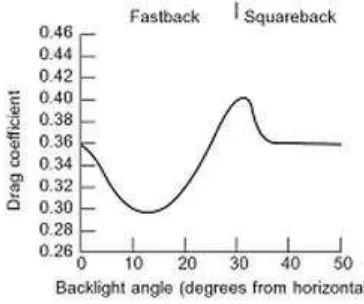
[image:20.595.229.411.227.379.2]These vortices cause the upper surface flow to remain attached to the surface over backlight angle of 30 degrees. Therefore, air is drawn down over the rear of the car that creates a resulting force in both lift and drag directions. The backlight angle is therefore absolutely critical for this type of vehicles (Ahmed et al., 1984). Figure 2.4 below shows the effect of backlight angle to the drag coefficient. From the figure, the drag coefficient decreases up until 10 degrees, but increases to maximum at about 30 degrees.
Figure 2.4: Influence of backlight angle on drag coefficient (Source: Dominy, 2002)
2.2.2 Lift and Pitch Moment
8
2.2.3 Side Force and Yaw Moment
Side force and yaw moment produced on cars are very likely to the lift and pith moment of a wing at an angle of attack (Hucho & Sovran, 1993). From the top view, a car can be treated as a blunt airfoil that can generate lift and pitch moment when the angle of attack is greater than zero. On the contrary, the car requires large yaw angle for side force and yaw moment to be produced. Yawing moment is generated due to the center of pressure of the area enclosed by the pressure distributions on the leeward and windward sides is located forward of the car length. Yaw moment of a vehicle can also be explained by the difference between longitudinal forces acting on the left and right hand sides of the vehicle or different lateral forces acting on the front and rear axles (Reif, 2014). Yaw moment is undesirable because it tends to turn the car away from the wind, causing the vehicle to become unstable.
Side force and yaw moment are highly dependent on the rear end shape of a vehicle. Figure 2.5 shows the yaw moment and side force coefficient for a family of cars with different rear end shapes.
[image:21.595.124.523.466.617.2]9
Based on the Figure 2.5, the yaw moment and side force increase linearly for yaw angle, up to 20°. The increase of yaw moment and side force is mainly determined by the side view and cross-section shape of a vehicle. For example, a fastback type car will have a higher increase of the yaw moment compared to the squareback type car when the yaw angle increases. On the contrary, the side force is lower for the fastback car.
2.2.4 Yawing Stability
The aerodynamic stability of a vehicle is highly dependent on two different conditions. The first condition is that when a car is travelling at high speed in a straight line, then it experience lane change maneuverability. The second condition is the effect of steady crosswind and transient gusts. Both of these effects can be explained as the wind is not aligned with the road which the vehicle is travelling (Hucho & Sovran, 1993). Hence, the vehicle operates at a nonzero angle of yaw, producing side force and yaw moment. A free body diagram of vehicle operating at a nonzero yaw angle is illustrated in Figure 2.6.
Apart from gusts, driving conditions with yaw angle, to reach maximum
d
10
11
2.3 SPOILER
The spoiler is commonly used to improve the aerodynamic performance of the vehicle. The spoiler can be divided into front spoiler and rear spoiler. The front spoiler is installed below the front bumper to decrease the air flow underneath vehicle. The decrement of air flow underneath vehicle will reduce aerodynamic drag and lift. On the contrast, the rear spoiler is installed at the rear part of vehicle commonly located on top of the trunk. The rear spoilers also known as “wings” installed on racing car usually are inverted airfoils that produce negative lift. Inverted airfoil can greatly increase down force which is needed by a racing car. As a result, it can provide traction and increase the stability of race car under high speed racing. Despite racing car, spoilers are also introduced into passenger car due to the increase of vehicle speed. Based on Kodali and Bezavada (2012), a rear spoiler can reduce the lift coefficient by 80% with a mere 3% increase in drag. A mid reduction in aerodynamic drag by installing optimized spoiler is proven by Hu and Wong (2011) after they studied the flow around a simplified high speed passenger car.