UNIVERSITI TEKNIKAL MALAYSIA MELAKA
Bone Scaffold Design Selection by Using
Analytical Hierarchy Process (AHP)
This report submitted in accordance with requirement of the Universiti Teknikal Malaysia Melaka (UTeM) for the Bachelor Degree of Manufacturing Engineering
(Design) (Hons.)
by
LOO HEOY SHIN B 051110214 910904-10-5378
DECLARATION
I hereby, declared this report entitled “Bone Scaffold Design Selection by Using Analytical Hierarchy Process (AHP) Tool” is the results of my own research except as
cited in references.
Signature : ……….
Author’s Name : ………
APPROVAL
This report is submitted to the Faculty of Manufacturing Engineering of UTeM as a partial fulfillment of the requirements for the degree of Bachelor of Manufacturing Engineering (Design) (Hons.). The member of the supervisory is as follow:
i
ABSTRAK
ii
ABSTRACT
iii
DEDICATION
This project is dedicated to My beloved parents
Dearest Siblings
Honourable Supervisor, Panels and other lecturers Loyal friends
My prayer upon You will be embedded in my heart wherever I go and whenever I go and whenever I think of You
iv
ACKNOWLEDGEMENT
First of all, I am grateful to Gautama Buddha for giving me the health and strength to complete this project.
I would like to thank with sincere heart to my dearest supervisor, Dr Shajahan bin Maidin. Without his knowledge and commitment in guiding me along the year, this project will not be completed. Dr Shajahan has given me a lot of idea on how to design the bone scaffold during this project carry on. He always give me positive minded so that I will not feel stressful to work under him. Once again I would like to thank him for all the comments and amendments he has given me with his patience towards my deficiency.
I also would like to express my greatest gratitude to lecturers especially En. Zulkeflee bin Abdullah and Dr. Suriati binti Akmal who have been my panels for my final year project. A lot of idea and improvement they have comment during presentation and report for PSM 1 helps me a lot to do the amendment for the final report. Besides that, I also would like to thanks to my panel 3 for presentation PSM 1, En Baharudin bin Abu Bakar and PSM 2, Pn Ruzy Haryati binti Hambali. During the presentation, they had direct and indirectly voice out the problem that exist in my project and lead me to discuss with my supervisor for improvements.
Last but not least, I would like to give my thanks to the support from my parents as well as my beloved family. They always give me the mentally encouragement to complete this project entirely and I will always feel grateful that I having them as my family.
v CHAPTER 1 INTRODUCTION ... 1
1.1 Background ... 1
1.2 Problem Statement ... 3
1.3 Objectives ... 3
1.4 Scope ... 4
CHAPTER 2 LITERATURE REVIEW ... 5
2.1 Additive Manufacturing (AM) ... 5
Process flow of AM ... 6
Methods of AM ... 7
Application of AM ... 18
Advantages and Disadvantages of AM ... 24
2.2 Additive Manufacturing in Medical Field ... 27
vi
Challenge in medical field ... 33
2.3 Human’s bone structure ... 35
Formation of bones ... 37
CHAPTER 3 METHODOLOGY ... 58
3.1 Project Planning ... 58
Gantt Chart ... 63
3.2 3D CAD Drawing – CATIA Software ... 66
Procedure to Draw a Body Part ... 67
3.3 Material Selection ... 71
Procedure to Select the Material from CES Software ... 71
3.4 Simulation of the Design Body Part ... 72
3.5 Design Selection and Material Selection ... 74
Analytical Hierarchy Process (AHP) ... 74
vii
CHAPTER 4 RESULTS ... 81
4.1 Design of the Bone Scaffold ... 81
4.2 Material Selection ... 88
Alumina Bio-ceramic ... 88
Calcium Phosphate Bio-ceramic ... 89
Bio-active Glasses ... 90
4.3 ANSYS Simulation ... 91
Animation Result from Simulation ... 93
4.4 Summary ... 99
CHAPTER 5 ANALYSIS OF DATA & DISCUSSION ... 100
5.1 Simulation Data ... 100
Compression Simulation Test ... 101
Torsional Simulation Test ... 105
5.2 Analytical Hierarchy Process (AHP) Tool Analysis ... 109
Design Selection... 109
Material Selection ... 115
5.3 Summary ... 120
CHAPTER 6 CONCLUSION ... 121
6.1 Summary ... 121
6.2 Further Recommendation ... 124
viii
LIST OF TABLES
Table 2.1: Comparison between SOLIDWORKS and CATIA ... 54
Table 3.1: Gantt Chart for PSM 1 ... 64
Table 3.2: Gantt Chart for PSM 2 ... 65
Table 3.3: Factor/ Criteria that Listed for Different Option ... 75
Table 3.4: Pairwise Comparison Scale... 76
Table 3.5: Pairwise Comparison Matrix and Synthesizing Judgement... 77
Table 3.6: Priority Vector for each of the Option ... 77
Table 3.7: Pairwise Comparison Matrix for Three Factor / Criteria in Selection ... 78
Table 3.8: Overall Priority Ranking ... 78
Table 4.1: Properties of Alumina Bio-ceramic ... 89
Table 4.2: Properties of Calcium Phosphate Bio-ceramic ... 90
ix
Table 5.1: Result from the Compression Simulation Test ... 101
Table 5.2: Result from the Torsion Simulation Test ... 105
Table 5.3: Factors/ criteria for each of the design ... 110
Table 5.4: The Priorities of the Design in terms of the Ease to Clip ... 111
Table 5.5: The Priorities of the Design in terms of the Cost ... 112
Table 5.6: The Priorities of the Design in terms of the Strength ... 112
Table 5.7: The Priorities of the Design in terms of the Pressure ... 113
Table 5.8: The Priorities of the Criterion ... 113
Table 5.9: The Priorities of the Design in term of Criterion ... 114
Table 5.10: The Priorities of the Design ... 114
Table 5.11: Factors/ criteria for each of the material ... 116
Table 5.12: The Priorities of the Material in terms of the Cost ... 117
Table 5.13: The Priorities of the Material in terms of the Strength ... 117
Table 5.14: The Priorities of the Material in terms of the Pressure ... 117
Table 5.15: The Priorities of the Criterion ... 118
Table 5.16: The Priorities of the Material in term of Criterion ... 118
x
LIST OF FIGURES
Figure 1.1: Biodegradable, polymeric scaffold ... 2
Figure 2.1: Basic process flow of AM ... 6
Figure 2.2: AM System Classifications ... 7
Figure 2.3: Photochemical Machining Process ... 8
Figure 2.4: Process flow of colour stereolithography (Bartolo & Gibson, 2011) ... 9
Figure 2.5: SLA System ... 10
Figure 2.6: Product of SLA ... 10
Figure 2.7: SLS System ... 12
Figure 2.8: Product of SLS ... 12
Figure 2.9: EBM Machine... 14
Figure 2.10: EBM System ... 15
Figure 2.11: Product of EBM ... 15
Figure 2.12: FDM uPrint machine ... 17
xi
Figure 2.14: Product of FDM ... 18
Figure 2.15: General application of Additive Manufacturing (AM) System ... 19
Figure 2.16: Application of AM in aerospace field ... 21
Figure 2.17: Application of AM in Automotive field ... 22
Figure 2.18: Process of the manufacture the building using AM technology ... 23
Figure 2.19: Final building structure that build by using AM technology... 24
Figure 2.20: Endosseous implants... 28
Figure 2.21: Subperiosteal implants ... 28
Figure 2.22: Transosteal Implants ... 29
Figure 2.23: Polymer Substrate Neural Implants ... 30
Figure 2.24: Spinal Cord Stimulation ... 31
Figure 2.25: Cages of Spinal Implants ... 32
Figure 2.26: Human Skeleton ... 36
Figure 2.27: Evolution of Osteoblasts and Osteoclasts in the Formation of Bones ... 38
Figure 2.28: Bone Formation from Hyaline Cartilage Model... 38
Figure 2.29: Common Types of Bone Fracture ... 40
Figure 2.30: Achilles Tendon Position ... 42
Figure 2.31: Scaffolding for Construction ... 45
xii
Figure 2.33: Cell-based Tissue Regeneration Approach for the Repair of Bone Defects
(Alvarez & Nakajima, 2009) ... 46
Figure 2.34: Process flow of Sketching using SOLIDWORKS ... 52
Figure 2.35: Process flow of Sketching using CATIA ... 53
Figure 3.1: Process Flow Chart ... 60
Figure 3.2: Design Process Flow for Single Body Part ... 67
Figure 3.3: Design Process Flow for Layering of the Body Part ... 68
Figure 3.4: Final Design of the Body Part ... 69
Figure 3.5: Flow Chart of Designing Bone Scaffold by using CATIA ... 70
Figure 3.6: Start Page and Filtration of the Material Selection by Using CES ... 71
Figure 3.7: Comparison between Two Filtration and Select the Best Material ... 72
Figure 3.8: Hierarchy of Decisions ... 75
Figure 4.1: Isometric View of Design 1 ... 82
Figure 4.2: Isometric View of Design 2 ... 82
Figure 4.3: Isometric View of Design 3 ... 83
Figure 4.4: Isometric View of Design 4 ... 83
Figure 4.5: Projection View of Design 1 ... 84
xiii
Figure 4.7: Projection View of Design 3 ... 86
Figure 4.8: Projection View of Design ... 87
Figure 4.9: Display Page from Project Schematic of ANSYS Simulation (Completed) . 91 Figure 4.10: Define the Material Properties ... 92
Figure 4.11: Simulation running for the Result ... 93
Figure 4.12: Total Deformation of Bone Scaffold in 1 second. ... 94
Figure 4.13: Equivalent Stress Effect of Bone Scaffold in 1 second. ... 95
Figure 4.14: Normal Stress Effect of Bone Scaffold in 1 second. ... 95
Figure 4.15: Total Deformation of Bone Scaffold in 1 second. ... 96
Figure 4.16: Equivalent Stress Effect of Bone Scaffold in 1 second. ... 97
Figure 4.17: Shear Stress Effect of Bone Scaffold in 1 second ... 98
Figure 4.18: Report Preview from the ANSYS Simulation. ... 98
Figure 5.1: Hierarchy of Decisions for Design Selection ... 111
1
1
CHAPTER 1
INTRODUCTION
This chapter will introduce the core of the study, Additive Manufacturing (AM) and the product to be designed, Scaffold. The problem statement, objective and scope also will be discussed in this chapter.
1.1 Background
Additive manufacturing (AM) which defined by the American Society for Testing and Materials (ASTM) is the process of making objects from 3D model data by joining the materials layer by layer. It is opposed to subtractive manufacturing technologies, such as traditional machining. The application of the AM have functional models, direct part production, fit and assembly, pattern and prototype, visual aids and others. Application of AM help to enable the final product are geometrical freedom and multiple material combination. The geometrical freedom included design complexity, parts consolidation, part customization and multiple assemblies.
2
customize the parts. In the term, AM had accelerate the product development, offer design freedom, optimizes part structures and allows for a high degree of functional integration.
Scaffold (as shown in Figure 1.1), is one of the application in Additive Manufacturing (AM) has introduced to help to regenerate the tissue and bone, including limbs and organs (Salgado, Coutinho, & Reis, 2004). The scaffold is a three dimensional structure composed of polymer fibers. The scaffold is inserted and grip with the damaged cells and begin to rebuild the missing bone and tissue through the tiny holes. As the bone and tissue generate, the scaffold is absorbed into the body and disappears completely. The design of the scaffold basically is complex in geometry and customize. Hence, the manufactured of scaffold depend on the Additive Manufacturing (AM) and the production rate is low.
Figure 1.1: Biodegradable, polymeric scaffold (Retrieved September 17, 2015, from
3
1.2 Problem Statement
A lot of people will have problem with their bones. It could be due to disease, injury due to accident, or as well as bone defects since we are born. The fracture usually will heal itself for a minor defect problem but it is difficult for the major defect. Usually, some implantation process need to carry out for major problem. Since there are demands in the bone implantation, there will be market demand for the bon scaffold. There are variety of design of bone scaffold available in the market with wide range of properties and price. In this project, four different designs of bone scaffold will be proposed with different geometrical shape and material. By understanding and undergoing necessary simulation, the best scaffold design with the most advantage in helping the tissue regenerative process will be determined. The design that chosen must be good quality in term of the strength that can sustain the force and pressure that exerted by the patient during daily activities.
1.3 Objectives
The objectives of this project as below:
1) To study about the Additive Manufacturing (AM) and bone scaffold design in medical application.
2) To design four different structural form of bone scaffold to aid the tissue regenerative process using CAD software.
3) To run the compression and torsional simulation by correlate the design of the bone scaffold and the selected bio-material.
4
1.4 Scope
5
2
CHAPTER 2
LITERATURE REVIEW
This chapter discuss about the reference that we used to refer for further research. The reference may be in the form of books, journal, articles and conference paper. The major topic that we discuss in this chapter have Additive Manufacturing (AM), Additive Manufacturing in Medical Field (implants), Human Bone Structure and Scaffold.
2.1 Additive Manufacturing (AM)
6 Process flow of AM
Based on the Figure 2.1, the AM process begins with the foundation of the three-dimensional (3D) model through the utilization of computer-aided design (CAD) software such as SolidWork, AutoCAD and CATIA. To fix the drawing that draw triangulated representation of the mannequin, the CAD-based 3D model, then requires to be saved as standard tessellation language (. STL) file. The draft that is drawn need to arrive at some simulation analysis to assure the model that will be produced is compatible with the parameter properties.
Side by side, the draft from the STL file which in CAD based will sent to the AM device. In this process, the software will slides the data file into individual layers, which are sent as instructions to the AM device. The drawing will support the generation which is auto built by the system itself. At that time, the AM device started to operate and creates the model by adding the material on top from one to another top until the object is the buildup. Once the model created, there is needed the process of cleanup and post curing to clean the surface of the model created. There are forms of finishing activities may be required, which, depending on the material used and complexity of the wares. Some of the parts of the object may require the secondary processing which include sanding, filing, polishing, material fill or painting.
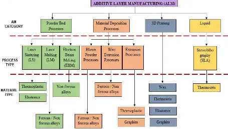
7 Methods of AM
According to the Figure 2.2, we can conclude that there are three layers distributed under Additive Manufacturing (AM): AM Category, process type and material type. Basically, AM are divided into 4 categories which are powder bed processes, material deposition processes, 3D printing and liquid. In the figure, different colors represent the different categories. Few types of processes and material that can be used for the particular groups are grouped under these categories. In this sub chapter, we are discuss only four of the process type under different categories.
Figure 2.2: AM System Classifications
(Retrieved September 27, 2014, from
8 2.1.2.1 Stereolithography (SLA)
Stereolithography also known as laser lithography, which this approach is the most popular AM technologies among others (Bartolo & Gibson, 2011). Lithography emphasizes on the art of reproduction of graphics objects and includes different techniques, example of photographic reproduction, photo sculpture, xerography and Microlithography. On the other hand, the modern type of photolithography AM system has tackled the theory of the computer generated graphics mixed with photosensitive materials to endorse the 3D products. The initial project of modern AM systems was presented by a patent of the system which the phase change of material (photochemical cross-linking or degrading a polymer) by the intersection of two radiation beam and form a 3D object. This essential feature called photochemical machining (as shown in Figure 2.3).
Figure 2.3: Photochemical Machining Process (Retrieved September 27, 2014, from
http://osp.mans.edu.eg/shazem/NTM/NonTraditionalMachining.html)