DESIGN OF INTEGRATED FILTER-ANTENNA FOR WIRELESS COMMUNICATIONS
NOOR AZIAN BINTI JONO
ii
UNIVERSTI TEKNIKAL MALAYSIA MELAKA
FAKULTI KEJURUTERAAN ELEKTRONIK DAN KEJURUTERAAN KOMPUTER
BORANG PENGESAHAN STATUS LAPORAN PROJEK SARJANA MUDA II
Tajuk Projek : DESIGN OF INTEGRATED FILTER-ANTENNA FOR WIRELESS COMMUNICATIONS.
Sesi
Pengajian : 1 3 / 1 4
Saya NOOR AZIAN BINTI JONO
Mengaku membenarkan Laporan Projek Sarjana Muda ini disimpan di Perpustakaan dengan syarat-syarat kegunaan seperti berikut:
1. Laporan adalah hak milik UniversitiTeknikal Malaysia Melaka.
2. Perpustakaan dibenarkan membuat salinan untuk tujuan pengajian sahaja. 3. Perpustakaan dibenarkan membuat salinan laporan ini sebagai bahan pertukaran
antara institusi pengajian tinggi. 4. Sila tandakan ( √ ) :
SULIT*
*(Mengandungi maklumat yang berdarjah keselamatan atau kepentingan Malaysia seperti yang termaktubdi dalam AKTA RAHSIA RASMI 1972)
TERHAD** **(Mengandungi maklumat terhad yang telah ditentukan oleh organisasi/badan di mana penyelidikan dijalankan)
TIDAK TERHAD
Disahkan oleh:
__________________________ ___________________________________ (TANDATANGAN PENULIS) (COP DAN TANDATANGAN
PENYELIA)
iii
DECLARATION
“I hereby, declare that this report is the results of my own work except for quotes as citied in the references.”
Signature :
Author’s Name : NOOR AZIAN BINTI JONO
iv
APPROVAL
“I hereby declare that I have read this report and in my opinion this report is sufficient in terms of the scope and quality for the award of Bachelor of Electronic Engineering
(Wireless Communication) With Honours.”
v
vi
ACKNOWLEDGEMENT
First of all, praise to Allah S.W.T., the Almighty God, for blessing me with good health, lots of patience, and the strength to finish this Final Year Project (FYP) in time and successfully. Thank you, Abah and Ibu for being so understanding with all the work loads. I really appreciated all your encouragement, love and support all this while to me.
My greatest appreciation and thank you goes to my supervisor, Dr. Zahriladha bin Zakaria who has been providing me knowledge and also helping me in completing this final year project. I really appreciated all your kindness, inspirational ideas, suggestion and motivations that make me perform to my very best of my abilities.
I would also like to extend my sincerest thanks to Sam Weng Yik for giving me permission to work and make improvement based on his previous project. To all my lecturers and friends, thanks to all your support and help directly or indirectly.
vii
ABSTRACT
viii
ABSTRAK
ix
CONTENTS
CHAPTER CONTENTS PAGE(S)
PROJECT TITLE i
BORANG PENGESAHAN STATUS LAPORAN ii
DECLARATION iii
APPROVAL iv
ACKNOWLEDGEMENT v
ABSTRACT vii
ABSTRAK viii
CONTENTS ix
LIST OF FIGURES xii
LIST OF TABLES xv
LIST OF ABBREVIATION xvi
1 INTRODUCTION 1.1 INTRODUCTION 1
1.2 PROBLEM STATEMENTS 1
1.3 OBJECTIVE 2
1.4 SCOPE OF PROJECT 2
1.5 METHODOLOGY 3
1.6 ORGANIZATION OF THESIS 4
2 LITERATURES REVIEW 2.1 Background 5
2.1.1 Basic Concept of Antenna 7
2.1.2 Basic Concept of Filter 7
2.2 Lowpass Prototype Network 10
x
2.4 Resonant Circuit Theory of Filter 13
2.4.1 Single-Mode Filter 13
2.4.2 Dual-Mode Filter 15
2.5 Resonant Circuit Theory Antenna 17
2.5.1 Single-mode Antenna 17
2.5.2 Dual-mode Antenna 18
2.6 Resonant Circuit Theory of Integrated Filter and Antenna. 19
2.6.1 Integrated Filter and Antenna (Single-mode) 19
2.6.2 Integrated Filter and Antenna (Dual-mode) 20
2.7 Microstrip Patch Antenna 21
2.7.1 Introduction 21
2.7.2 Overview of Microstrip Patch Antenna 22
2.8 Review of Integrated Microwave Filter and Antenna 23
3 METHODOLOGY 3.1 Introduction 25
3.2 Design Specifications 26
3.3 Ideal Circuit Design 26
3.4 Physical Layouts 28
3.4.1 Evolution proposed of Filter-antenna design 28
3.4.2 Rectangular Microstrip Patch Antenna (Design A) 30
3.4.3 T-Shape Resonant Filter (Design B) 33
3.4.4 Design of Single-Mode Filter-Antenna (Design C) 34
3.4.5 Design of Dual-Mode Filter-Antenna (Design D) 35
3.5 Simulation Process 36
3.6 Fabrication Process 37
4 RESULT AND DISCUSSION 4.1 Single-mode antenna 38
4.1.1 Rectangular microstrip patch antenna 2.4GHz 38
4.1.2 Rectangular microstrip patch antenna 5.8GHz 39
4.2 Single-mode T-Shape Resonator filter 40
xi
4.2.2 Filter for 5.8GHz. 41 4.3 Second-Order Chebyshev Bandpass Filter Prototype for
lump element. 42
4.4 T-shape resonator filter. 44 4.5 Integrated Filter-antenna (single-mode). 45 4.6 Integrated Filter-antenna (Dual-mode) 46
4.7 Measurement Result. 47
5 CONCLUSION AND SUGGESTION
5.1 Conclusion 53
5.2 Future Work 54
REFERENCES 55
xii
LIST OF FIGURES
NO. TITLE PAGE(S)
1.1 Project Flowchart 3
2.1 Distribution of frequency spectrum in wireless communication system. 6 2.2 Block diagram of the RF front end of wireless communication
systems in the base station. 6
2.3 Ideal Response of Different Type of Filters 9 2.4 The frequency response of the filter in Ω. 10 2.5 Lowpass to Bandpass Circuit Transformation (a) Lowpass response
(b) Bandpass response. 13
2.6 Bandpass Transformation for: (a) an inductor, (b) a capacitor. 13
2.7 Lowpass prototype of single-mode filter 14
2.8 Equivalent circuit of single-mode bandpass filter 14
2.9 Lowpass prototype of dual-mode filter 16
2.10 Equivalent circuit of dual-mode bandpass filter 16
2.11 Lowpass prototype of single-mode antenna 17
2.12 Equivalent circuit of single-mode antenna 18
2.13 Lowpass prototype of dual-mode antenna 18
2.14 Equivalent circuit of dual-mode antenna 18 2.15 Lowpass prototype equivalent circuit of integrated second order
filter/antenna. 19
xiii
2.19 Microstrip Patch Antenna. (a) Rectangular Patch. (b) Circular Patch 22 2.20 Layout of Integration of pass-band filters in patch antennas 24
2.21 Design Prototype 24
3.1 Rectangular microstrip patch antenna in form of low-pass equivalent circuit. 27 3.2 Circuit of the rectangular microstrip patch antenna (a) Single-mode,
(b) Dual-mode. 27
3.3 Circuit of the microstrip d T-shape resonator filter (a) Single-mode,
(b) Dual-mode. 27
3.4 Evolution of integrated filter-antenna design from (a) antenna without coupling line, (b) antenna with coupled line, (c) single-mode filter-antenna, (d) side view filter-antenna, (e) Physical layout coupled line, (f) conversion ideal circuit to T-shape resonator filter layout and (g) Dual-band
filter-antenna. 29
3.5 Geometry of Rectangular patch Antenna. 30 3.6 Basic measurement T-shape resonator filter. 33
3.7 Geometry of Single-mode Filter-Antenna. 34
3.8 Geometry of Dual-mode Filter-Antenna 35
3.9 Flowchart of Fabrication Process 37
4.1 Rectangular microstrip patch antenna 2.4GHz 39
4.2 Result of antenna 2.4GHz. 39
4.3 Rectangular microstrip patch antenna 5.8GHz 40
4.4 Result of antenna 5.8GHz. 40
4.5 Layout of T-Shape Resonator filter for 2.4GHz. 41
4.6 Result of BandPass Filter at 2.4GHz. 41
4.7 Layout of T-Shape Resonator filter for 5.8 GHz. 42
4.8 Result of BandPass Filter at 5.8 GHz. 42
4.9 Circuit simulation Bandpass Filter Prototype 43
4.10 Result of BandPass Filter 43
4.11 Circuit simulation of T- Shape Resonator filter. 44
xiv
4.13 Circuit representation of a single-mode integrated rectangular patch
antenna and T-shape resonator filter. 45
4.14 Simulated results of the integrated single-mode rectangular patch
antenna and T-shape resonator filter. 46 4.15 Circuit representation of a dual-mode filter-antenna. 46 4.16 Simulated results of integrated dual-mode rectangular patch antenna
and T-shape resonator filter. 47
4.17 Manufacturing integrated dual-mode rectangular patch antenna
and T-shape resonator filter (a) Front View, (b) Back view. 48
4.18 Measurement setup on DUT using VNA 48
4.19 Measured results of integrated dual-mode rectangular patch
antenna and T-shape resonator filter. 49 4.20 Graph comparison between the simulated and measured
return loss (S11) versus frequency. 49
4.21 Simulation three dimension radiation pattern of the filter-antenna. 50 4.22 Simulation two dimension radiation pattern of the filter-antenna. 51 4.23 Comparison radiation pattern of the filter-antenna.
xv
LIST OF TABLES
NO. TITLE PAGE(S)
2.1 Summary of evolution Integrated Filter-antenna 23
3.1 Design specification Filter and antenna 26
3.2 Dimension of Antenna. 31
3.3 Dimension of physical layout filter 33
3.4 Dimension of physical layout single mode filter-antenna 35
3.5 Optimize dimension Dual-band filter-antenna. 36
xvi
LIST OF ABBREVIATION
ADS - Advanced Design System Software
EM - Electromagnetic
TE - Transverse Electric
TEM - Transverse Electromagnetic TM - Transverse Magnetic
TX - Transmit
AUT - Antenna Under Test
CST - Computer Simulation Technology dB - Decibel
GHz - Gigahertz
RF - Radio Frequency RL - Return Loss RX - Receiver
1
CHAPTER 1
INTRODUCTION
1.1 INTRODUCTION
A Wireless Local Area Network (WLAN) links two or more devices using some wireless distribution method and usually providing a connection through an access point to the wider internet. This gives users the mobility to move around within a local coverage area and still be connected to the network in a specific range of frequency. In order to gives comfortable and compactness in wireless communication system, both filter and antenna are need designed together. To achieve this purpose, both filter and antenna must meet perfectly the requirement which is get optimum desired return loss for both elements by using suitable impedance matching. The concept of integration filter and antenna combine together into one module is to reduce the overall size of element and to improve the performance which is the transition loss in both elements located in the RF front-end subsystems as shown.
1.2 PROBLEM STATEMENT
2 a distributed filter and is implemented using transmission line resonators. The transmission line filters are not compact, and in many applications where size is an issue. This results in a large size and a high cost as well as performance (loss).
1.3 OBJECTIVE
The main objectives of the project are as follows:
1) To design dual-mode integrated filter-antenna at frequency 2.4 GHz and 5.8 GHz that suitable for WLAN applications.
2) To analyze the characteristic of integrated filter-antenna such as S-parameter, radiation pattern, directivity and bandwidth.
3) To fabricate and validate the proposed concept.
1.4 SCOPE OF PROJECT
The scope of this project is to design for integrated of filter-antenna with dual-band for 2.4 GHz and 5.8 GHz which is based on the IEEE 802.11 for WLAN standard. The Filter-antenna is simulated by using software Advanced Design System Software (ADS) for ideal simulation and the Computer Simulation Technology (CST) software with the FR4 board. The antenna will be optimized to fulfill the specification and the performance requirements of the Filter-antenna. The compact integrated of filter-antenna is fabricated by using FR4 board with dielectric constant, εr= 4.6 and tangent loss of substrate, tan δ = 0.019. Besides, the thickness
3
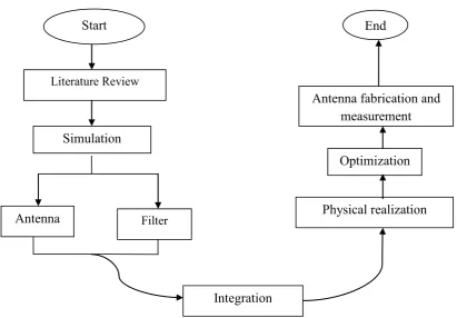
1.5 METHODOLOGY
The flow chart of this project was as shown in the Figure 1.1. This project was start with the literature review through journals and books in order to identify the aspects that related to the integrated filter-antenna. Before design the integrated filter-antenna, the design process will start with design the single filter, single filter, single filter-antenna and lastly dual-band filter-antenna. Initial stage, the designing are simulate use Agilent advances design system (ADS), the follow simulate by using CST software. After the simulation design for the dual-band filter-antenna filter-antenna is done and the result is desirable, the filter-antenna will be fabricated by using FR4 board with chemical etching technique. Next, measurement for the prototype antenna will be done.
[image:19.596.107.519.372.658.2]
Figure 1.1: Project Flowchart Start
Literature Review
Simulation
Antenna Filter
Integration
Physical realization Optimization Antenna fabrication and
4
1.6 ORGANISATION OF THESIS
In this final year project report, the thesis is organized into five chapters. Chapter 1 is about the introduction about the dual-band filter-antenna antenna for the WLAN application, problem statement, objective, scope of work and methodology.
Chapter 2 is covers the background of the basic concept of antenna and filter. Then, discuss about concept lowpass prototype network and how to transform to bandpass circuit. The resonant circuit of this design procedure also discuss here from the single filter and antenna, dual filter and antenna, single-mode integrated filter-antenna, and last dual-mode integrated filter-antenna. Also, some overview of microstrip patch antenna and review of integrated microwave filter-antenna is discussed.
Chapter 3 is discussed about the methodology of this project. The design can classify into three parts, which are single filter and single antenna, single integrated filter-antenna and dual-mode integrated filter-antenna. FR4 board is used in order to design a dual-mode integrated filter-antenna. The design process that involved for the design of dual-mode integrated filter-antenna is included calculations and parametric study. The simulation, fabrication and measurement process are discussed in this chapter.
Next, Chapter 4 is about the result and the discussion for the result that obtained from the simulation or measurement.
5
CHAPTER 2
LITERATURE REVIEW
This chapter is discussed on the literature review for the topic of design of integrated filter-antenna for wireless communication. Firstly, the background of the integrated filter-antenna that discussed by compared with the conventional separated antenna and filter systems. Then, the basic antenna parameters also discussed in this chapter, which included radiation pattern, bandwidth, return loss, directivity, and bandwidth have been highlighted in this chapter.
2.1 Background
6 The concept of integration filter and antenna combine together into one module is to reduce the overall size of element and to improve the performance which is the transition loss in both elements located in the RF front-end subsystems as shown in Figure 2.2. There have been numerous studies of literature about the evolution of filter-antenna from the single-mode until to dual-band applications. Therefore, many method had been apply which presented by [1][2][3], it using edge-fed gap-coupling mechanism to produce single-mode filter-antenna. In addition, there a design filter-antenna using coplanar wave guide (CPW) has been presented in [4] to improve band-edge selectivity and good stop-band suppression. In [5] it implements filter-antenna as system-on package (SOP), by using this concept it able to support higher frequency up to 66 GHz, also can provide high gain, and fan-beam radiation pattern.
Figure 2.1: Distribution of frequency spectrum in wireless communication system.
[image:22.596.179.528.532.667.2]
Figure 2.2: Block diagram of the RF front end of wireless communication systems in the base station.
TX filter
RX filter
power amplifier
low noise amplifier
up-converter
down-converter antenna
RX/TX diplexer
TX
7 2.1.1 Basic Concept of Antenna
Antenna is an electrical device that able to coverts electric power into electromagnetic waves and vice versa. These devices use to transmit and receive electromagnetic wave. Typically, most antennas are resonant devices which to handle efficiently under specific given narrow frequency band [15].
2.1.2 Basic Concept of Filter
8 In order to design microwave filter, there have been several developed over the last few decades, most of the design procedures for microwave filters are still based on Cohn’s paper [8]. There are three steps in order to design microwave filter which are:
1) Begin with common mathematical models, and then an equivalent circuit prototype is designed.
2) After that, covert the prototype elements into real filter structure, by estimates are calculated for the physical layout of the filter dimension.
3) Lastly, get optimize value on the filter response by the physical layout. In this case, inductors, capacitors and resistors are remaining as passive elements. [9]
The basic ladder filters that are normally used can be dividing into 4 types [10]:
i. Butterworth filters; ii. Chebyshev filters; iii. Elliptical filters; iv. Linear phase filters.