COMPARATIVE STUDY OF FUZZY LOGIC SPEED CONTROLLER IN
VECTOR CONTROLLED PMSM DRIVE: MINIMUM NUMBER OF
FUZZY RULE - BASE
SITI NOORMIZA MAT ISA
ZULKIFILIE IBRAHIM
FAZLLI PATKAR
UNIVERSITI TEKNIKAL MALAYSIA MELAKA
Comparative Study of Fuzzy Logic Speed Controller in Vector
Controlled PMSM Drive: Minimum Number of Fuzzy Rule-Base
Siti Noormiza Mat Isa, Zulkifilie Ibrahim, Fazlli Patkar
Abstract-This paper presents a comparative study on fuzzy rule-base of fuzzy logic speed control with vector-controlled Permanent Magnet Synchronous Motor (PMSM) drive. Fuzzy rule-base design is viewed as control strategy. All fuzzy rules contribute to some degree in obtaining the desired performance. However, some rules tired weakly do not contribute significantly to the final result and can be eliminated. 'Standard design' of fuzzy rule-base of fuzzy logic controller is identified from numerous publications which is 49 rules is used in order to obtain great speed tracking response. It
is possible to minimize the complexity of controller's design by reducing number of rule-base from standard 49 rules to 9 rules. Simulation results that verify appropriateness of the approach are included. A comparison of speed response between both designs is studied. Sensitivity of the designs to load disturbance and changes in command settings is studied and also being compared to demonstrate the effectiveness of the reduced rule-base.
I. INTRODUCTION
Nowadays, fuzzy logic (FL) speed controller is well-known with its superior performance in the research
community worldwide. It has been proven by many
simulations and experimental verifications by numerous publications with diversity of industrial drive applications such as high performance DC drives [ l ], vector controlled Induction Motor [2]-[4] , Permanent Magnet Synchronous Motor [5]-[9], Brushless DC Motor [10] and Switched Reluctance Motor [l l], [12].
Various publications present comparison between the operation of drive with speed control by FL and PI techniques. Then the main conclusion verified that FL control determines superior performance [2]-[4] , [6], [9]. However, the papers are focused just on the speed performance meanwhile the parameters of the FL controller are distinctive and fix.
Theoretically, FL is based on human reasoning, providing algorithms which can convert a set of linguistic rules based
Manuscript received June 26, 2009.
Siti Noonniza Mat Isa is with the Electrical Engineering Department, Universiti Teknikal Malaysia Melaka, Mal aysia (e-mail: siti [email protected]).
Zulkifilie Ibrahim is with the Electrical Engineering Department, Universiti Tekn ikal Malaysi a Melaka, Malays ia (phone : 606-555 2202; fax: 606-5 55 2222; e-mail : drzulkifilie@utem .edu.my).
Fazlli Patkar is with the Electrical Engineering Department, Universiti Teknikal Malaysia Melaka, Malaysia (phone: 606-55 5 2352; e-mail: fazlli @lutem.edu .my).
on expert knowledge into an automatic control strategy. There is no need of mathematical models to deal with a problem, but skill is needed to create the rules in a particular FL controller [I], [6] , [9]. Reference [13] also mentioned that FL controller essentially is a multi-parameter controller, whose performance depends on the selected shape of membership function, rule base and scaling factor. This means a comparison and verification on the varying parameters can be described in order to determine the strength of the controller itself. Hence, it can be concluded that the varying parameters in terms of shape of membership
function , number of rule-base and scaling factor
determination have great influence in obtaining the strength of FL controller with intention to attain the desired performance. This point is also supported by [14] which mentioned that all fuzzy rules contribute to some degree to the final inference or decision, however, some rules fired weakly do not contribute significantly to the final decision and may be eliminated (reduced) . Therefore, a study of minimizing the fuzzy rule-base is presented in this paper.
The performance of vector controlled three-phase current-fed induction motor, from the control point of view, can be equivalent to the de motor drive whereby it decouples flux and torque control by instantaneous stator current space vector components can be achieved relatively easily [3], [8] , [15] . Therefore, beginning from the successful performance of vector control technique to induction, it may be considered that this kind of speed control loop design can be implemented to any type of AC drives including Permanent Magnet Synchronous Motor [6]-[9] , [16] and Switched Reluctance Motor [12].
The drive used in the study comprises a permanent magnet synchronous motor with vector control technique . Current control of PWM Voltage Source Inverter (VSI) is performed in stationary reference frame, using hysteresis current controllers.
From the literature that have been reviewed, most papers utilize triangular membership function s with overlap, seven for speed error and seven for change in speed error, so that 7x7 = 49 rules are produced [5], [6], [16] , [17] . This means 49 rules is a standard approach for the FL speed control with PMSM drive application.
Based on the above points, this paper aims to attempt to provide a comparison regarding speed drive operation with
utilizing 49 rules as 'standard design' and 9 rules as 'case design' in FL speed controller. All simulation work is realized in MATLAB program.
II. DESCRIPTION OF THE SYSTEM
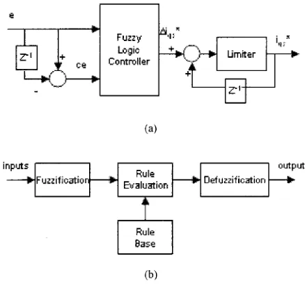
Fig. I presents a speed control system of the vector controlled PMSM drive. The rotor speed, Wr is compared
with Wr * and the resulting error is processed in the
controller. The output of controller is reference torque, T* which is then has been limited by a limiter in order to generate the q-axis reference current, iqs *. (Refer to Fig. 2(a)). At the mean time, d-axis reference current, icts* is set to zero. Both d-axis and q-axis stator currents generate three phase reference currents (i. *, ib * and ic *) through Park's Transformation which are compared with sensed winding currents (i., ib and ic) of the PMSM. The current errors are fed to hysteresis current controllers which generate switching signals for the voltage source inverter. Thus, by obtaining winding currents of the system, the speed response is obtained.
セG@ セ
Q
Mゥ⦅、ウ⦅J⦅]⦅oセMGMセセセセセセMゥM。「⦅」セセセNL@
Fig. I. Configuration ofFLC based vector controlled PMSM drive
This paper uses the standard approach of FL controller. The width of triangular membership function is divided equally in a range with overlap, either 7x7 rules or 3x3 rules. Input and output scaling factors are determined through initial design applied to rated speed until the speed response matches as closely as possible to the step rated speed command [4], [7] by implementing 49 rules.
The standard structure of fuzzy logic is given in Fig. 2 with inputs are speed error, e and change in speed error, ce and output is change in q-axis reference current, Mqs * [2], [4]-[6], [I I], [16]. The FLC executes the rule base taking the fuzzy variables e and ce as the inputs and quantity of Mqs * as the output are processed in the defuzzification unit as illustrated in Fig. 2(b ). For the present work, Mamdani type fuzzy inference is used [ 4].
A comparison of FL speed controller for different number of fuzzy rule-base which is 'standard design' and 'case design' is studied. The focus is on the speed response during start-up under no load, load disturbance operation and step change in reference speed setting. The investigation of fuzzy controllers is also carried out for several selected speed command in such a way to further strengthen the result obtained. The research details are as follows:
• Rated step speed command is applied at zero time under
no-load conditions;
• Rated load torque is applied at time instant t = 0.04 sec;
• Speed reference is reduced by I 0% of the previous
setting at time instant t = 0.08 sec;
• Initial step speed command is changed to 209 rad/s, I 04 rad/s and 52 rad/s speed command.
In addition, the reverse operation is also tested.
e
.
.
Fuzzy '" Logic Controller
(a)
Rule Evalu;;rtion
Rule Base
(b)
Defuzzific;;rtion
Fig. 2. (a) Fuzzy Logic Controller (b) Internal Structure ofFLC
III. DESIGN OF Fuzzy LOGIC SPEED CONTROLLER
The main goal of the control system is to track the command speed by reducing the complexity of fuzzy rule-base design of fuzzy logic controller while maintaining the performance obtained by 'standard design'.
A. Scaling Factor Calculation
The role of scaling factor is similar to gain coefficients in a conventional controller, and affects the stability, oscillations and damping of the system, hence needs to be chosen with utmost care [17]. Three scaling factors represented by G0 Gee and Gcu are chosen using known
motor data given for fuzzification, as well as for obtaining the actual output of the command current. There is always an input limitation for FLC, so that for convenience inputs and output are always ョッイュ。ャゥセ、@ into [-2,2] interval. Rated speed of the motor is 314 rad/s and an assumption is made that this value is the maximum speed of operation of the motor. Thus, maximum speed error is 314 for start-up from standstill and the scaling factor for the speed error is obtained as [ 4 ], [7]:
G, = 11314:::: 0.00318 (I)
[image:3.595.281.500.138.342.2] [image:3.595.13.249.285.374.2]on the basis of rated inertia and maximum torque that the motor is allowed to develop, taking sampling time 20µs.
Te max = J,/P(liw/T,) --+liw = 2.3438 rad/s
G,e =flee= l/(e(Ts) - e(O)) = ll!iw = 0.4267 (2)
Output scaling factor is set to Gc11 = I.
B. Design of Fuzzy Rule-Base
In this study, in order to determine the controller output from the measured system variables, a fuzzy relation matrix is established. The fuzzy relation matrix gives a relationship between fuzzy set characterizing controller inputs and fuzzy set characterizing controller outputs. Below, the fuzzy rule base matrix for 'standard design' and 'case design' are represented by Table 1 and Table II respectively. As mentioned before, the rules for the 'standard design' are
determined through literature review from many
publications. Meanwhile, the rules for the 'case design' parameters are determined by standard approach with reducing the number of fuzzy rule-base. The linguistic elements used are the same as those used in most of the publications [2], [9]. Fixed-step mode is chosen for the computational time interval. Numerical method for solving differential equations is Dormand-Prince [8] and simulating period is 0.1 second. Nominal parameters for the test motor are showed in Table III.
TABLE!
MATRIX OF 'STANDARD DESIGN'
Sneed error, e
NL NM NS ZE PS PM PL
.,
NL NL NL NL NL NM NS ZECJ
..;
0 NM NL NL NL NM NS ZE PS
..
..
.,
"'O
.,
NS NL NL NM NS ZE PS PM.,
Q.. ZE
"' NL NM NS ZE PS PM PL
.:
.,
PS NM NS ZE PS PM PL PLOJ)
=
«: PM NS ZE PS PM PL PL PL..c:
u
PL ZE PS PM PL PL PL PL
Seven terms are assigned in Table I: NL, negative large; NM, negative medium; NS, negative small; ZE, zero; PS, positive small; PM, positive medium; and PL, positive large. Three terms are assigned in Table II: N, negative; ZE, zero; and P, positive. Each fuzzy variable is a member of the subsets with a degree of membership µ varying between 0 and 1. As mentioned before, for convenience, the rules have been written in matrix form and should be interpreted as (Refer to Table I ):
[image:4.597.279.498.54.639.2]IF 'speed error is NS' AND 'change in speed error is PS' THEN 'change in q-axis reference current is ZE'.
TABLE II MATRIX OF 'CASE DESIGN'
Speed error, e N ZE
.:
.,
N N N., "'O CJ
OJ) . , ..;
ZE N ZE
= .,
0セ@ Q., li..
..c: "' .. p ZE p
u .,
TABLE III
PMSM TEST MOTOR
Parameter
Maximum torque JO Nm
Rated torque 1.7Nm
Rated current 2.7 A Maximum current JOA
p
ZE
p p
Value
Rated speed 314 rad/s (3000 rpm)
Inertia 0.000256 kgm2
Winding resistance 2.67
n
Winding inductance 11.5 mH Magnet flux 0.1210 Vs/rad Rated frequency 150 HzPole pairs 3
DC link voltage 320V
NL NM NS ZE PS PM PL
(a)
N ZE p
(b)
The shape of the fuzzy sets on the two extreme ends of the universe of discourse is taken as trapezoidal whereas all other intermediate fuzzy sets are triangular with overlap to each other as standard approach and the constant are divided equally in the range of -2 and 2 based on the number of membership functions either seven or three as illustrated in Fig. 3 [l], [3]. This operation can be performed by several methods which is max-min reasoning and center of gravity (or centroid) defuzzification method are used, as those methods are most frequently used in many literatures [l],
[4], [6].
All the scaling factors, shape of membership function, method of fuzzification and method of defuzzification are predefined and kept constant during the research except the number of rules.
IV. SIMULATION RESULTS
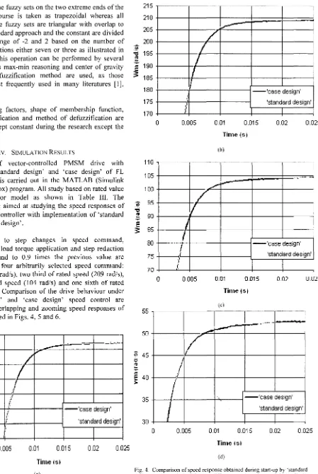
The study of vector-controlled PMSM drive with implementing 'standard design' and 'case design' of FL speed controller is carried out in the MATLAB (Simulink and Fuzzy Toolbox) program. All study based on rated value of the test motor model as shown in Table III. The investigations are aimed at studying the speed responses of the fuzzy speed controller with implementation of 'standard design' and 'case design'.
The response to step changes in speed command, subsequent rated load torque application and step reduction of speed command to 0.9 times the previous value are studied next for four arbitrarily selected speed command: rated speed (314 rad/s), two third of rated speed (209 rad/s), one third of rated speed (I 04 rad/s) and one sixth of rated speed (52 rad/s). Comparison of the drive behaviour under 'standard design' and 'case design' speed control are performed by overlapping and zooming speed responses of the types illustrated in Figs. 4, 5 and 6.
320
MセM ...___:.... ...
•-310
セ@;..o"
300
-·
.'{i
...,
290
":
-
"'
280
:::::
3:
270
/
I
.I
.I 1'··
I' I'
- 'case design'
"
,.
I'
260
IJ' 'standard design'250
0
0.005
O.D1 O.D150.02
O.D25Timejsl
(a)
215 210 205 200
:zy·
"I:: 195
r:
,. 190 ,..
セ@
185180 175 170
110 105 100
セ@ 95
"I::
;.
90,.. ,..
3:
8580 75 70
55
50
,..
c: 40
5::
35
30
0
-...
0
0
/
I
l
L.-7
I
I
I
•I
--'case design'
,\
ll 'standard design' \
0.005 O.D1 0.015 O.D2 O.D25
Time (SI (b)
... ,.,.,.,-... ...
.
-
·-.,,,.,.,.
-/
I
.;
J
I
--'case design'I
'standard design'Nセ@
\'
0.005 O.D1 O.D15 O.D2 0.025
Time1s1
(c)
__ .... T ... :·=1·
,,=, LL]セセᄋ@...,_
-
セ@I/
II
--'case design' 'standard design'
0.005 O.D1 0.0·15 O.D2 O.D25
Time Isl
(d)
[image:5.597.77.526.13.683.2]Fig. 4 presents good speed responses of the motor drive during start-up from standstill and accelerated to the speed command without load. The results show almost similar performances are obtained by both designs and the responses are clearly consistent with no overshoot and negligible steady state error. It is evident that the 'case design' has acceptable performance and it seems settled at the same moment whereby the difference of settling time between both controllers is approximately 5 ms.
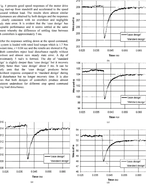
After the responses settling down at the speed command, the system is loaded with rated load torque which is 1. 7 Nm at instant time, t = 0.04 sec and the results are showed in Fig.
5. Both controllers reject load disturbance rapidly without overshoot and almost zero steady state error. A dip of approximately 5 rad/s is formed. The dip of 'standard design' is slightly deeper than 'case design' but it recovers slightly faster than 'case design' about 5 ms. It can be clearly seen that the 'case design' produces better undershoot response compared to 'standard design' during load disturbance but no longer recovery time. It is also shows that both designs of controllers produce almost consistent undershoot for different step speed command during load disturbance.
313
セMᄋMMM
-· 1
-- ... LLN⦅NNNLLLNMMNセᄋヲATNGMNNセ@ ....セMMM
- -
i
J"
¥
312:::
":'
--...
311:::::
;:
310
J
/
,:·
,1.
i'
-'case design'309 'standard design'
308
O.D25 O.D35 0.045 0.055 0.065
Timetsl
(a)
208 + - - - + - - - +
Mセ@
-::: 207 + - - - + - - - i
E
Iセ@ 206
q
I
205
---+---<n
- - 'case design'll
204 + - - - + - - -MMMKMMM[⦅MMMMN⦅Gウエ⦅。⦅ョ⦅、⦅。⦅イ、⦅、NNLN・⦅ウ⦅ゥァ⦅ョセᄋ@
203 + - - - + - - - + - - - ! - - - - I - - - - '
O.D25 O.D35 0.045 0.055 0.065
Time1s1
..
-
-
- MᄋNセ@ BBBGᄋセ@.
Ji
103-;
s
102セ@
101 10099 98
O.D25
Iセ@
O.D35
セ@
I
.l
-'case design' 'standard design'
O.o45 0.055 0.065
Time isl
(c)
52 l ... ···;;_.1."'.._ ... :..._.
Zセ@ 51
-::::
セ@
50
,..
,..
3
4948 47 46
0.025 0.035
,;--r-I
. .f
,i
Q'
セM
0.045
Time {SI (d)
1
--'case design'
I
'standard design'0.055 0.065
Fig. 5. Comparison of speed response to step rated load torque application obtained by 'standard design' and 'case design· for four different speeds: (a) at rated, 314 rad/s (b) at209 rad/s(c) at 104 rad/s (d)at 52rad/s
[image:6.595.22.519.20.653.2]'Ii
'O
.-:
,,.
セ@
セᄋ@
'O
:;
,,.
セ@
.l/i
....
g
セ@
320 315 310 305 300 295 290
.... . ...•...
I
'""' ""'"' d
___ ,> _ _ _ _ .... ___
I
\ 'standard design' I
\
:\
j\
\
"..
285
'
"'·
280
0075 0.08 0.085 0.09 O.IJ95 0.1
215
210 NNNZNZNセ[MNセ@ ...
205
200
195
\
\
\
190
185
Timelsf
(a)
1--'case design'
I
'standard design'Gセ@
-I
I
セ@
?
'Os
=
j
53
T .
m tセ@52 it·i..."" ... •i...::.· .. · · - - - t - - - ;
51 50
49 48
47
46
0075 0.08
.,
ᄋᄋセ@
0.085 0.09
Time is) (d)
'standard design'
0.095 0.1
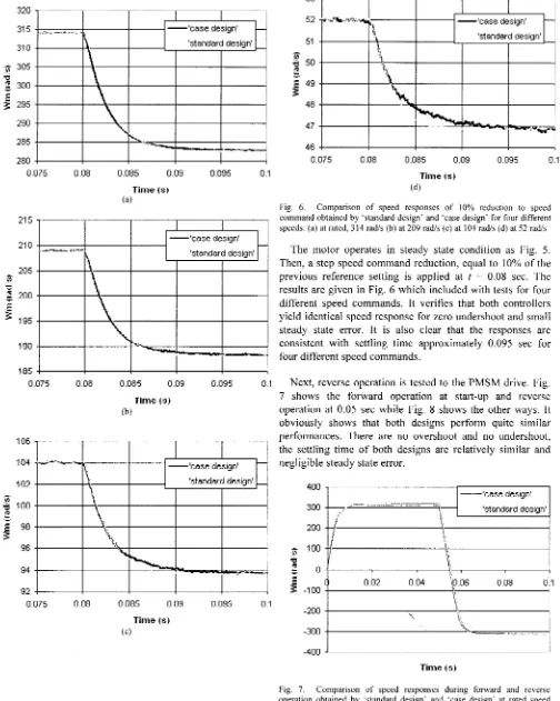
Fig. 6. Comparison of speed responses of I 0% reduction to speed command obtained by 'standard design' and 'case design' for four different speeds: (a) at rated, 314 rad/s (b) at 209 rad/s (c) at 104 rad/s (d) at 52 rad/s
The motor operates in steady state condition as Fig. 5. Then, a step speed command reduction, equal to 10% of the previous reference setting is applied at t = 0.08 sec. The results are given in Fig. 6 which included with tests for four different speed commands. It verifies that both controllers yield identical speed response for zero undershoot and small steady state error. It is also clear that the responses are consistent with settling time approximately 0.095 sec for four different speed commands.
0075 0.08 0.085 0.09 O.IJ95 0.1 Next, reverse operation is tested to the PMSM drive. Fig.
106
l
104102
100
98 96
94 92
0075 0.08
Time is)
(b)
--'case design' 'standard design'
0.085 0.09
Time {sl (c)
0.095 0.1
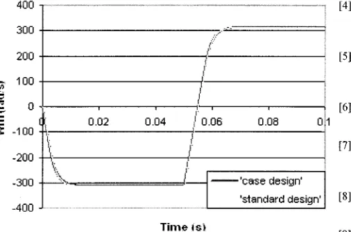
7 shows the forward operation at start-up and reverse operation at 0.05 sec while Fig. 8 shows the other ways. It
obviously shows that both designs perform quite similar performances. There are no overshoot and no undershoot, the settling time of both designs are relatively similar and negligible steady state error.
400 300 200
Nセ@ 100
"' :; 0
セ@
-100 0.02 -200-300
-400 セ@... .
0.04
',
! L I. I.
L
--'case design' 'standard design'
1
10.06 0.08 0:1
r
\,
;{,
\',
"'-Time (SI
[image:7.595.278.520.17.194.2] [image:7.595.16.520.22.653.2]400 セwセBGセG」@ セセT@
300 __ ,..-.·
(
200 r
ᄋセ@ 100
セ@
""
0.:::,
セ@
O.o2 0.04
I
0.08 0!1セ@
: 0.06-100
i.
,1I
I
-200
-300 --'case design'
-400 'standard design'
Time4si
Fig. 8. Comparison of speed responses during reverse and forward operation obtained by 'standard design' and 'case design' at rated speed command
Based on above results obtained, it can be seen that the 'case design' can provide acceptable performance as the 'standard design' performance in the FL control process. It
is essential to note that the difference of settling time of 5 ms during start-up and load disturbance do not give any significant changes in real-time environment.
V. CONCLUSIONS
A fuzzy rule-base design of fuzzy logic speed control has been studied for speed control of vector controlled PMSM drive. A set of fuzzy decision rules are formulated based on the literature review of the controller's design. In this paper, two types of fuzzy speed controller named 'standard design' and 'case design' is studied and being compared based on speed response during start-up under no load, load disturbance and changes in command settings. The simulation study is realized in MATLAB environment. The investigation of fuzzy controllers is carried out based on several selected speed response. The results are plotted in the same speed graph with intention to make details comparison based on visual observation on settling time, undershoot and recovery time. It is showed that both types of controller produce similar performance, thus, it is feasible to minimize the complexity of fuzzy logic controller by reducing the number of fuzzy rule-base from 49 rules to 9 rules.
REFERENCES
[l] J. N. Lygouras, P. N. Botsaris, J. Vourvoulakis, V. Kodogiannis, "Fuzzy Logic Controller Implementation for a Solar Air-conditioning System," Applied Energy 84, vol. 20, pp. 1305-1318, 2007 [Online]. The sciencedirect website. Available: http://www.elsevier.com/locate/apenergy
[2] V. Kumar, R. R. Joshi, "Hybrid Controller Based Intelligent Speed Control of Induction Motor," Journal of Theoretical and Applied Information Technology, 2005, pp. 71-75. [Online]. Available: http://www.jatit.org
[3] H. A. F. Mohamed, W. P. Hew, ''A Fuzzy Logic Vector Control of Induction Motor,'' in Proc. TECON 2000, vol. 3, pp. 324-328.
[4]
[5]
[6]
[7]
[8]
M. N. Uddin, T. S. Radwan, M. A. Rahman, ''Performances of Fuzzy Logic Based Indirect Vector Control for Induction Motor Drive."
IEEE Trans. On Industry Applications, vol. 38, pp. 1219-1225. Sept./Oct. 2002.
A. Karakaya, E. Karakas, "Performance Analysis of PM Synchronous Motors Using Fuzzy Logic and Self Tuning Fuzzy Pl Speed Controls," The Arabian Journal for Science and Engineering, vol. 33, pp. 153-177, Apr. 2008.
A. G. Aissaoui, M. Abid, H. Abid, A. Tahour, A. K. Zeblah, ''A Fuzzy Logic Controller for Synchronous Machine," Journal of Electrical Engineering, vol. 58, pp. 285-290, 2007.
M. N. Uddin, T. S. Radwan, M. A. Rahman, G. H. George, ·'Fuzzy Logic Based Position Control of Permanent Magnet Synchronous Motor," in Canadian Conference on Electrical & Computer Engineering, vol. 1, pp. 93-97, 2000.
T. Pham-Dinh, T. Nguyen-Thanh, "Fuzzy Speed Controller for Rotor Flux Oriented Control of Permanent Magnet Synchronous Machine." in Proc. !SEE 2007, pp. 72-78, Oct 2007.
[9] l. Goney, Y. Oguz, F. Serteller, "Dynamic Behaviour Model of Permanent Magnet synchronous Motor Fed by PWM Inverter and Fuzzy Logic Controller for Stator Phase Current, Flux and Torque Control of PMSM," in Proc. IEMDC'OJ, pp. 479-485, 2001. [IO] R. N. Tuncay, Z. Erenay, M. Yilmaz, 0.Ustun, "Rapid Control
Prototyping Approach to Fuzzy Speed Control of Brushless DC Motor," in Proc. ELECO '03, Dec 2003.
(11] M. G. Rodrigues, W. I. Suemitsu, P. Branco, J. A. Dente, L. G. B. Rolim, "Fuzzy Logic Control of a Switched Reluctance Motor,'' in
Proc. JSJE'97, vol. 2, pp. 527-531, Jul. 1997.
(12] Z. Yingchao, Z. Zhengming, G. Wei, S. Xiaoying, "High Performance Position Control System Based on SR-PM Motor," Tsinghua Science and Technology, vol. 12, pp. 614-619, Oct. 2007.
(13] Z. Ibrahim, E.Levi, D. Williams, "A Self-Tuning Method for Fuzzy Logic Speed Controller in High Performance AC Drives," in Proc. UPEC'98, vol. 2, pp. 819-822, Sep. 1998.
(14] C. Hung, B. Fernandez, "Minimizing Rules of Fuzzy Logic System by Using a Systematic Approach," IEEE Std., 1993.
(15] H. N. Nounou, H. Rehman, "Application of Adaptive Fuzzy Control to AC Machines," Applied Soft Computing, vol. 7, pp. 899-907, 2007 [Online]. The sciencedirect website. Available: http://www.elsevier.com/locate/apenergy
[16] B. Singh, B. P. Singh, S. Dwivedi, "DSP Based Implementation of Fuzzy Precompensated Pl Speed Controller for Vector Controlled PMSM Drive," IEEE Industrial Electronics and Applications, pp. 1-6, May 2006.
[17] A. Karakaya, E. Karakas, "The Speed Control of Permanent Magnet Synchronous Motor Using Fuzzy Logic and Self Tuning Fuzzy Pl Controller," in Proc. ELECO '05, Dec. 2005.
[image:8.595.24.277.17.184.2]