i
STEERING CONTROL FOR A CAR USING BACKSTEPPING CONTROL STRATEGY
LEONG SENG WAH
i
STEERING CONTROL FOR A CAR USING BACKSTEPPING CONTROL STRATEGY
LEONG SENG WAH
This report is submitted in partial fulfillment of the requirements for the award of Bachelor of Electronic Engineering (Industrial Electronics)
With Honours
Faculty of Electronic and Computer Engineering Universiti Teknikal Malaysia Melaka
ii
UNIVERSTI TEKNIKAL MALAYSIA MELAKA
FAKULTI KEJURUTERAAN ELEKTRONIK DAN KEJURUTERAAN KOMPUTER
BORANG PENGESAHAN STATUS LAPORAN
PROJEK SARJANA MUDA II
Tajuk Projek : ………
Sesi
Pengajian : ………
Saya ……….. (HURUF BESAR)
mengaku membenarkan Laporan Projek Sarjana Muda ini disimpan di Perpustakaan dengan syarat-syarat kegunaan seperti berikut:
1. Laporan adalah hakmilik Universiti Teknikal Malaysia Melaka.
2. Perpustakaan dibenarkan membuat salinan untuk tujuan pengajian sahaja.
3. Perpustakaan dibenarkan membuat salinan laporan ini sebagai bahan pertukaran antara institusi
pengajian tinggi.
4. Sila tandakan ( ) :
SULIT*
(Mengandungi maklumat yang berdarjah keselamatan atau kepentingan Malaysia seperti yang termaktub di dalam AKTA RAHSIA RASMI 1972)
TERHAD* (Mengandungi maklumat terhad yang telah ditentukan oleh
organisasi/badan di mana penyelidikan dijalankan)
TIDAK TERHAD
Disahkan oleh:
__________________________ ___________________________________ (TANDATANGAN PENULIS) (COP DAN TANDATANGAN PENYELIA)
Alamat Tetap: ………...
………...
Tarikh: ……….. Tarikh: ………..
STEERING CONTROL FOR A CAR USING BACKSTEPPING CONTROL STRATEGY
2008 / 2009
LEONG SENG WAH
61, JALAN TUPAI,
iii
“I hereby declare that this report is the result of my own work except for quotes as cited in the references”
Signature : .………..:
Author : LEONG SENG WAH
iv
“I hereby declare that I have read this report and in my opinion this report is sufficient in terms of the scope and quality for the award of Bachelor of Electronic
Engineering (Industrial Electronics) With Honours”
Signature : ………
Supervisor’s Name : EN AHMAD SADHIQIN BIN MOHD ISIRA
v
vi
ACKNOWLEDGEMENT
I have successfully completed my thesis which is a partial fulfillment of requirements for the Bachelor of Electronic Engineering (Industrial Electronic) With Honours.
I would like to take this opportunity to express my gratitude and thanks to my supervisor, En. Ahmad Sadhiqin bin Mohd Isira for his guidance that had allowed me to complete this final year project. I would also like to thank Faculty of Electronic and Computer Engineering (FKEKK) and Universiti Teknikal Malaysia Melaka (UTeM) for giving me an opportunity to further my studies here.
vii
ABSTRACT
viii
ABSTRAK
ix
CONTENT
CHAPTER ITEM PAGE
PROJECT TITLE i
REPORT STATUS APPROVAL FORM ii
DECLARATION iii
SUPERVISOR APPROVAL iv
DEDICATION v
ACKNOWLEDGEMENT vi
ABSTRACT vii
ABSTRAK viii
CONTENT ix
LIST OF TABLE xiii
LIST OF FIGURE xiv
LIST OF ABBREVIATION xvii
I INTRODUCTION 1
1.1 Introduction of the Project 1
1.2 Objectives 2
1.3 Problem Statement 2
1.4 Scope 3
x
II LITERATURE REVIEW 6
2.1 Introduction 6
2.2 BMW’s Active Steering 7
2.3 Delphi’s Quadrasteer 8
2.4 Literature Review 9
2.4.1 Mathematical Modeling 9
2.4.2 Track Modeling 10
2.4.3 Disturbances 11
2.4.4 Controllers 11
III MATHEMATICAL MODEL 13
3.1 Introduction 13
3.2 The Single Track Model 13
3.3 The Simulink Modeling in MATLAB 19
3.4 The Vehicle Numerical Values 21
3.5 Controllability 22
3.6 The Disturbances 23
3.6.1 Braking Torque Disturbance 23
3.6.2 Crosswind Disturbance 24
IV CONTROLLER MODEL 26
4.1 Introduction 26
4.2 Integrator Backstepping 26
4.3 Single Integrator Backstepping 27
xi
4.5 Linear Quadratic Regulator 33
V SIMULATION AND RESULT 37
5.1 Introduction 37
5.2 Different Road Conditions 37
5.2.1 Braking Torque Disturbance 38
5.2.1.1 Lateral/Side slip 38
5.2.1.2 Yaw 40
5.2.1.3 Longitudinal 42
5.2.2 Crosswind Disturbance 44
5.2.2.1 Lateral/Side slip 44
5.2.2.2 Yaw 46
5.2.2.3 Longitudinal 48
5.3 Different Speed 50
5.3.1 Braking Torque Disturbance 50
5.3.1.1 Lateral/Side slip 50
5.3.1.2 Yaw 53
5.3.1.3 Longitudinal 55
5.3.2 Crosswind Disturbance 58
5.3.2.1 Lateral/Side slip 58
5.3.2.2 Yaw 60
5.3.2.3 Longitudinal 63
VI DISCUSSION AND FUTURE RECOMMENDATION 66
6.1 Introduction 66
xii
6.2.1 Results for Different Road Conditions
with Braking Torque Disturbance 67
6.2.2 Results for Different Road Conditions
with Crosswind Disturbance 68
6.2.3 Results for Different Vehicle Speeds 68
6.3 Future Recommendation 69
VII CONCLUSION 70
REFERENCES 71
APPENDIX A 72
xiii
LIST OF TABLE
No. TITLE PAGE
xiv
LIST OF FIGURE
No. TITLE PAGE
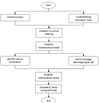
1.1 The methodology flow of the process. 4
2.1 BMW’s Active Steering System 7
2.2 The Quadrasteer v2.0 Four Wheel Steering System 9
2.3 Example of a two track model. 10
2.4 Example of a single track or bicycle model. 11
3.1 Single track model for car steering 14
3.2 Block diagram of a car steering 14
3.3 Kinematics variables 15
3.4 Simulink simulation together with the controller 20
3.5 The controllability output by MATLAB 23
3.6 Braking torque disturbance signal 24
3.7 Crosswind disturbance signal 25
5.1.1 Side slip angle for braking torque at 70 m/s on dry road (µ= 1) 38
5.1.2 Side slip angle for braking torque at 70 m/s on wet road (µ= 0.5) 39
5.1.3 Side slip angle for braking torque at 70 m/s on slippery
road (µ= 0.15) 39
5.2.1 Yaw rate for braking torque at 70 m/s on dry road (µ= 1) 40
5.2.2 Yaw rate for braking torque at 70 m/s on wet road (µ= 0.5) 41
5.2.3 Yaw rate for braking torque at 70 m/s on slippery road (µ= 0.15) 41
xv
5.3.2 Longitudinal force for braking torque at 70 m/s on wet road (µ= 0.5) 43
5.3.3 Longitudinal force for braking torque at 70 m/s on slippery
road(µ= 0.15) 43
5.4.1 Side slip angle for crosswind at 70 m/s on dry road (µ= 1) 44
5.4.2 Side slip angle for crosswind at 70 m/s on wet road (µ= 0.5) 45
5.4.3 Side slip angle for crosswind at 70 m/s on dry road (µ= 0.15) 45
5.5.1 Yaw rate for crosswind at 70 m/s on dry road (µ= 1) 46
5.5.2 Yaw rate for crosswind at 70 m/s on wet road (µ= 0.5) 47
5.5.3 Yaw rate for crosswind at 70 m/s on slippery road (µ= 0.15) 47
5.6.1 Longitudinal force for crosswind at 70 m/s on dry road (µ= 1) 48
5.6.2 Longitudinal force for crosswind at 70 m/s on wet road (µ=0.5) 49
5.6.3 Longitudinal force for crosswind at 70 m/s on slippery
road (µ= 0.15) 49
5.7.1 Side slip angle for braking torque at 1 m/s on dry road (µ= 1) 51
5.7.2 Side slip angle for braking torque at 10 m/s on dry road (µ= 1) 51
5.7.3 Side slip angle for braking torque at 30 m/s on dry road (µ= 1) 52
5.7.4 Side slip angle for braking torque at 50 m/s on dry road (µ= 1) 52
5.8.1 Yaw rate for braking torque at 1 m/s on dry road (µ= 1) 53
5.8.2 Yaw rate for braking torque at 10 m/s on dry road (µ= 1) 54
5.8.3 Yaw rate for braking torque at 30 m/s on dry road (µ= 1) 54
5.8.4 Yaw rate for braking torque at 50 m/s on dry road (µ= 1) 55
5.9.1 Longitudinal force for braking torque at 1 m/s on dry road (µ= 1) 56
5.9.2 Longitudinal force for braking torque at 10 m/s on dry road (µ= 1) 56
5.9.3 Longitudinal force for braking torque at 30 m/s on dry road (µ= 1) 57
5.9.4 Longitudinal force for braking torque at 50 m/s on dry road (µ= 1) 57
5.10.1 Side slip angle for crosswind at 1 m/s on dry road (µ= 1) 58
xvi
5.10.3 Side slip angle for crosswind at 30 m/s on dry road (µ= 1) 59
5.10.4 Side slip angle for crosswind at 50 m/s on dry road (µ= 1) 60
5.11.1 Yaw rate for crosswind at 1 m/s on dry road (µ= 1) 61
5.11.2 Yaw rate for crosswind at 10 m/s on dry road (µ= 1) 61
5.11.3 Yaw rate for crosswind at 30 m/s on dry road (µ= 1) 62
5.11.4 Yaw rate for crosswind at 50 m/s on dry road (µ= 1) 62
5.12.1 Longitudinal force for crosswind at 1 m/s on dry road (µ= 1) 63
5.12.2 Longitudinal force for braking torque at 10 m/s on dry road (µ= 1) 64
5.12.3 Longitudinal force for braking torque at 30 m/s on dry road (µ= 1) 64
xvii
LIST OF ABBREVIATION
IEEE - Institute of Electrical and Electronics Engineers LQR - Linear Quadratic Regulator
DOF - Degree Of Freedom SBW - Steer by Wire
MP - Momentary Pole
CG - Center of Gravity
m - Mass of Vehicle
v - Velocity of Vehicle
β - Sideslip of Body
ψ - Yaw Angle
r - Yaw Rate
yF
F - Front Axle Lateral Force in Chassis Coordinate
yR
F - Rear Axle Lateral Force in Chassis Coordinate
x
F - Retarding Force
J - Moment of Inertia
F
l - Length between Front Axle to the Center of Gravity
R
l - Length between Rear Axle to the Center of Gravity
zD
M - Disturbance Torque
F
β - Sideslip Angle at Front Axle
R
β - Sideslip Angle at Rear Axle
F
xviii
R
α - Rear Tire Sideslip Angle
F
δ - Front Steering Angle
R
δ - Rear Steering Angle
ytF
F - Lateral Force in Front Tire Coordinate
ytR
F - Lateral Force in Rear Tire Coordinate
µ - Adhesion Coefficient
F
C - Front Tire Cornering Stiffness
R
C - Rear Tire Cornering Stiffness
Co - Controllability km/h - Kilometers per Hour
1
CHAPTER I
INTRODUCTION
1.1 Introduction of the Project
Losing control of a car at high speeds is a common problem. These accidents occur because of the driver’s failure to understand the many situations that could result in loss of control. They have failed to understand the limit of their vehicle. A city car which is small is not designed to be driven at highway speeds while tires with poor grip increase the chances of losing control. Such problems are due to the driver’s negligence to do proper maintenance. A new driver would not even be able to fully control the car, let alone to understand the hidden dangers of disturbances.
2
1.2 Objectives
The objective of this project is being defined as below:
i. To identify the method of producing a mathematical model of a car steering. ii. To identify and simulate the disturbance signal
iii. To identify the effects of disturbance towards the vehicle’s sideslip angle and yaw.
iv. To identify the requirements of the backstepping controller’s requirement and its implementation.
v. To design a steering control system for a car using the backstepping control strategy.
1.3 Problem Statement
3
1.4 Scope
The scope of this project is to focus on the method of developing the vehicle’s mathematical model especially that of the steering system. The mathematical model will then be transferred into Simulink in MATLAB for simulation. The graphs relating to the yaw and sideslip are then generated by adding a simulated disturbance. On the second part of the project, the focus will be on developing a back stepping controller and will then be integrated into the mathematical model to improve vehicle stability. This project will only focus on simulation and does not involve any hardware.
1.5 Outline of Methodology
Literature reviews are conducted to further understand the development of steering control. The project will simply focus on the construction of the mathematical model of a vehicle steering. From there, a state feedback strategy controller is designed and attached to the vehicle steering which is known as the active steering. This project will not involve any hardware building as is only a simulation. Majority of this information are referred to the book titled Robust Control: The Parameter Space Approach[1].
4
[image:23.612.129.527.250.665.2]Having to understand the basics, some research was done on active steering through multiple sources including the IEEE’s journals. From these journals, much information can be gathered to further understand the problems and solutions applied to the same concept of active steering. The journals can only give a simple overview of the research done as most information still requires the readers to further their research by referring their respective references books. This is to ensure that the readers can fully understand the entire system more clearly.
Figure 1.1: The methodology flow of the process. Start
End Identify Various
Parameters
Establish Mathematical Model
Control Strategy: Backstepping & LQR
Understanding Simulation Tools Literature Study
Evaluate & Verify (Using MATLAB)
Establish Mathematical Model
5
Chapter 2 of the project is to identify the nature of the project which is a simulation type only. After completing the literature study, a research on the current Active Steering technology and its many research which can be found in the IEEE’s website. By doing so, we are able to identify the method used to simulate the system.
In chapter 3, by referring to the references, a standard mathematical modeling for a car steering is established. The modeling is only limited to three degree of freedom which is sufficient to represent the vehicle’s steering characteristics. The vehicle simulation is verified by comparison with the references.
In chapter 4, the type of controller to be implemented is chosen. The backstepping controller is capable of controlling multiple types of condition at one moment, thus improving system efficiency. The design and implementation of the backstepping controller is studied carefully and executed. The mathematical model is combined with the backstepping controller which results in the active steering. The controller is verified by adding the Linear Quadratic Regulator (LQR).
Chapter 5 consists of the simulation and results. The simulation is executed with many types of variables being used as to show the performance of the controller at different types of conditions. By matching the pattern of the controllers and the uncontrolled model, it proves that the results are correct and that the simulation is in line with other types of simulation for vehicle steering.
Chapter 6 is about the discussion and future recommendation. The discussion is for the results generated. The future recommendation for this project is also discussed here as this project can be further develop to complete a vehicle simulation.