i
“TELEPHONE OPERATED REMOTE CONTROL”
FAZLIANA BINTI HASSAN
This report is submitted in partial fulfillment of requirements for the award of Bachelor of Electronic Engineering (Industrial Electronics) with Honours.
Faculty of Electronic and Computer Engineering University Teknikal Malaysia Melaka
ii
UNIVERSTI TEKNIKAL MALAYSIA MELAKA
FAKULTI KEJURUTERAAN ELEKTRONIK DAN KEJURUTERAAN KOMPUTER
BORANG PENGESAHAN STATUS LAPORAN
PROJEK SARJANA MUDA II
Tajuk Projek : TELEPHONE OPERATED REMOTE CONTROL
Sesi Pengajian : 1 0 / 1 1
Saya FAZLIANA BINTI HASSAN ___________________________________ _____ (HURUF BESAR)
mengaku membenarkan Laporan Projek Sarjana Muda ini disimpan di Perpustakaan dengan syarat-syarat kegunaan seperti berikut:
1. Laporan adalah hakmilik Universiti Teknikal Malaysia Melaka.
2. Perpustakaan dibenarkan membuat salinan untuk tujuan pengajian sahaja.
3. Perpustakaan dibenarkan membuat salinan laporan ini sebagai bahan pertukaran antara institusi
pengajian tinggi. 4. Sila tandakan ( √ ) :
SULIT*
*(Mengandungi maklumat yang berdarjah keselamatan atau kepentingan Malaysia seperti yang termaktub di dalam AKTA RAHSIA RASMI 1972)
TERHAD** **(Mengandungi maklumat terhad yang telah ditentukan oleh organisasi/badan di mana penyelidikan dijalankan)
TIDAK TERHAD
Disahkan oleh:
__________________________ ___________________________________
(TANDATANGAN PENULIS) (COP DAN TANDATANGAN PENYELIA)
iii
DECLARATION
“I hereby declare that this report is the result of my own work except for quotes as cited in the references.”
Signature: ……….. Author: FAZLIANA BINTI HASSAN
iv
“I hereby declare that I have read this report and in my opinion this report is sufficient in terms of the scope and quality for the award of Bachelor of Electronic
Engineering (Industrial Electronics) with Honours.”
Signature: ……… Supervisor’s name: ENGR. MUZAFAR BIN ISMAIL
v
Dedicated to my parents, Abdullah Bin Mat Akib and Hasnah Binti Hasan , my
vi
ACKNOWLEDGEMENT
First of all, I would like to thank God for his blessing, and I also want to express my deepest gratitude to my supervisor Engr.Muzafar Bin Ismail for support and guidance throughout this project running and completion of this report.
My deepest appreciation also goes out to Pn. Rohaidah Binti Mahidin who gave me many needed support, encouragement and help throughout my project’s improvement, not to forget, thanks to my family and fellow friends who encouraged me.
vii
ABSTRACT
viii
ABSTRAK
ix
TABLE OF CONTENTS
CHAPTER PAGES
TELEPHONE OPERATED REMOTE CONTROL ... i
DECLARATION ... iii
ACKNOWLEDGEMENT ... vi
ABSTRACT ... vii
ABSTRAK ... viii
LIST OF TABLE ... xii
LIST OF FIGURE ... xiii
CHAPTER I ... 1
INTRODUCTION ... 1
1.0 PROJECT INTRODUCTION ... 1
1.1 PROJECT OBJECTIVES ... 2
1.2 PROBLEM STATEMENT ... 2
1.3 SCOPE ... 3
1.4 MOTIVATION OF THE WORK ... 3
1.5 METHODOLOGY ... 5
1.6 FLOW CHART ... 6
x
CHAPTER II ... 9
LITERATURE REVIEW ... 9
2.0 INTRODUCTION ... 9
2.1 METHOD OF THE CLOSE OR OPEN THE LIGHT OR FAN ... 10
2.2 TELEPHONE ... 11
2.2.1 INTRODUCTION ... 11
2.2.2 MOTHER EXCHANGES ... 13
2.3 DUAL-TONE MULTI-FREQUENCY SIGNALING ... 14
2.3.1 MULTIFREQUENCY SIGNALING ... 15
2.3.2 KEYPAD ... 16
2.3.3 SPECIAL TONE FREQUENCIES... 18
2.4.1 STRUCTURE OF PIC16F873 ... 20
2.4.1 PORT A ... 20
2.4.2 PORT B ... 21
2.4.3 PORT C ... 22
2.4.4 CONFIGURATION WORD OF PIC16F873 ... 24
2.4.5 HARDWARE OF THE PIC16F873 ... 26
CHAPTER III ... 30
METHODOLOGY ... 30
3.0 INTRODUCTION ... 30
3.1 PROJECT EXECUTION ... 32
3.1.1 HARDWARE DEVELOPMENT AND IMPLEMENTATION. ... 32
3.1.2 SOFTWARE DEVELOPMENT AND IMPLEMENTATION ... 33
3.2 METHODOLOGY ... 34
3.3 FLOW CHART MOVEMENTS PROCESS ... 35
xi
CHAPTER IV ... 39
RESULT AND DISCUSSION ... 39
4.0 INTRODUCTION ... 39
4.2 DISCUSSIONS OF EXPERIMENT ... 40
4.3 RESULTS ... 40
4.4 PROCEDURE RELAY AND LAMP PROCESS CONTINUED ... 43
4.5 RESULT OF THE TELEPHONE CONNECTION WITH THE MODEL 44 4.6 ADVANTAGES AND DISADVANTAGES THIS PRODUCT ON COMMERCIAL. ... 47
CHAPTER V ... 49
CONCLUSION AND SUGGESTIONS ... 49
5.0 CONCLUSION ... 49
5.1.1 SUGGESTIONS ... 50
REFERENCES ... 51
xii
LIST OF TABLE
NO. TITLE PAGES
Table 1: DTMF keypad frequencies (with sound clips)…….………..17
Table 2: functional encode or decode……….……….17
Table 3: Special Tone Frequency……….19
xiii
LIST OF FIGURE
NO TITLE PAGES
Figure 1.1: Currently issues in article …………..………4
Figure 1.2: Overview Project Flow………...…5
Figure 1.3: Gantt chart for Project PSM 1 ………..…….6
Figure 1.4: Gantt chart for Project PSM 2 ………..…….7
Figure 2.1: Switch Lights………10
Figure 2.2: Timer………10
Figure 2.3: Remote Control...11
Figure 2.4: Block diagram of SPC switching……….12
Figure 2.5: Call Progress Response………18
Figure 2.6: 1209Hz on 697Hz to make the 1 tone………..19
Figure 2.7: Logic Diagram for Port A ……….………..21
Figure 2.8: Logic Diagram for Port B……….…………22
xiv
Figure 3.1: Flowchart the Methodology of the Project………...34
Figure 3.2: Flow Chart Movements Process……….………..36
Figure 3.3: Block Diagram of the Movement System………....37
Figure 4.1: Circuit Diagram For Telephone Operated Remote Control………42
Figure 4.2: concept connection between relay and load (lamp)……….43
Figure 4.3: Model for Power Supply Is Connected………44
Figure 4.4: Model for Power Supply, Telephone Line is connected………….…….44
Figure 4.5: Model for Power Supply, Telephone Line is connected for lamp 1….…45 Figure 4.6: Model of Power Supply, Telephone Line is connected for lamp 2…..…45
Figure 4.7: Model of Power Supply, Telephone Line is connected for lamp 3…..…46
1
CHAPTER I
INTRODUCTION
1.0 PROJECT INTRODUCTION
In the world of the sophisticated and modern, there is a variety of equipment that has been created and modified for use as a day. Most products are designed to solve the various problems faced by each user. Normally, users often forget to switch off electrical appliances at home or anywhere else. So with this, our ideas emerge to create "Telephone Operated Remote Control”. I also believe that this project has the potential to spread in the near future to contribute to the use of home and office.
2
From the research I have conducted on the use of this tool, the concept of frequency conversion signal or a telephone line using DTMF in the toggle switch off electrical appliances at home and am an impact and effective results and quality. Accordingly, I deem that the project is to inspire and increase knowledge in the field of electronics.
1.1 PROJECT OBJECTIVES
The objectives in solving the problems are:-
1. To design system control component electric at home or office using line telephone and can control at long distance and can save the money, time and energy.
2. To produce a home control system is more advanced.
3. To design a tool that facilitates the control of home electrical equipment no matter where we are.
4. To study more about DTMF in the telephone coverage.
5. To learn the C language programming for PIC16F873 microcontroller.
1.2 PROBLEM STATEMENT
3
complain because they had to come home again to turn off the equipment. This situation has led to wastage of the cost, time and energy is due.
1.3 SCOPE
Work scope for this project including:-
1. This project consists of the designation of hardware architecture.
2. The two key elements in the development of this project are subjected to the usage of DTMF and another IC.
3. This project converge have procedure in convert bite DTMF to binary coded.
4. A successive invention of a project will follow some important point such as communication, planning, modeling, construction and deployment.
1.4 MOTIVATION OF THE WORK
4
landlord considers that there is in the house. It also will create tools that can also be applied to the area office.
5
1.5 METHODOLOGY
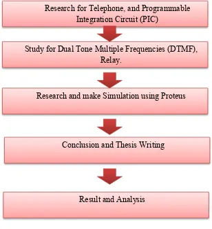
Implementation and works of the project are summarized into the flow chart as shown in Figure 1.1. Gantt charts as shown in Figure 1.2 show the detail of the works of the project that had been implemented in the first and second semester.
Figure 1.2: Overview Project Flow Research for Telephone, and Programmable
Integration Circuit (PIC)
Study for Dual Tone Multiple Frequencies (DTMF), Relay.
Research and make Simulation using Proteus
6
1.6 FLOW CHART
Figure 1.3: Gantt chart for Project PSM 1 N
O
ACTIVITY W
1 W 2 W 3 W 4 W 5 W 6 W 7 W 8 W 9 W 1 0 W 1 1 W 1 2 W 1 3 W 1 4 W 1 5 W 1 6 W 1 7 W 1 8 W 1 9
1 Discussion and getting PSM title from supervisor S E M E S T A B R E A K S T U D Y W E E K F I N A L E X A M 2 Information
searching 3 Preparation
of proposal 4 Proposal
conferencing 5 Submission
of proposal 6 Study of PIC
programming from books and internet 7 software
develop 8 Hardware
develop 9 Integration
7
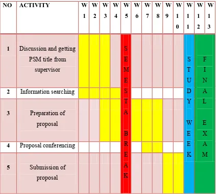
Figure 1.4: Gantt chart for Project PSM 2
NO ACTIVITY W
1 W 2 W 3 W 4 W 5 W 6 W 7 W 8 W 9 W 1 0 W 1 1 W 1 2 W 1 3
1 Discussion and getting PSM title from
supervisor S E M E S T A B R E A K S T U D Y W E E K F I N A L E X A M 2 Information searching
3 Preparation of proposal
4 Proposal conferencing
8
1.7 STRUCTURE OF THE THESIS
This thesis consists of five chapters including this introduction follow the university thesis standard which including objectives, scope of the works, problem statement, and motivation of the work. In second chapter present the literature review of interaction of Programmable Integration Circuit (PIC), Telephone Operate Remote Control, and method of the close or open the light or fan. The structure of telephone system also will be discussed in this chapter and its function within relay. The hardware and software analysis will be present at chapter three. Based on PIC programming and the flow how telephone operator remote control operation. In this chapter are also equipped with the methodology, process flow chart and block of movement system.
Chapter 4 represents the results of both simulation and hardware implementation. It also contains the analysis of the project that has been created. This chapter also contains picture and photo for the initial results of this project.
9
CHAPTER II
LITERATURE REVIEW
2.0 INTRODUCTION
During this developmental process, many references and studies have been done to meet the desired objectives. In the search for reference materials is an important factor in ensuring the overall effectiveness of the completed projects and reports.
In addition, it also can show consumers that this project has an understanding of the system developed by the author. So with this, some information related to this project has been sought and collected for the project will be known better. The study was made on the components used in this project.
10
The results of the study that was done, any weaknesses and advantages of the existing product were available. Any weakness in this product will be handled carefully, and all the good will be used to produce a product that has its own advantages and meet the needs of users.
2.1 METHOD OF THE CLOSE OR OPEN THE LIGHT OR FAN
1. Turn off the switch that is on the wall.
Figure 2.1: Switch Lights.
2. Using the timer (timer) to open and close the lights.