Master of Science in Electronic Engineering
Faculty of Electronic and Computer Engineering
LOW VOLTAGE AMPLIFICATION USING SELF
STARTING VOLTAGE REGULATOR FOR STORAGE
SYSTEM
Haslinah Binti Mohd Nasir
LOW VOLTAGE AMPLIFICATION USING SELF STARTING VOLTAGE REGULATOR FOR STORAGE SYSTEM
HASLINAH BINTI MOHD NASIR
A thesis submitted
in fulfillment of the requirements for the degree of Master of Science in Electronic Engineering
Faculty of Electronic and Computer Engineering
UNIVERSITI TEKNIKAL MALAYSIA MELAKA
DECLARATION
I declare that this thesis entitled “Low Voltage Amplification Using Self Starting Voltage
Regulator for Storage System” is the result of my own research except as cited in the
references. The thesis has not been accepted for any degree and is not concurrently
submitted in candidature of any other degree.
Signature : ...
Name : ...
APPROVAL
I hereby declare that I have read this thesis and in my opinion this thesis is sufficient in
terms of scope and quality for the award of Master of Science in Electronic Engineering.
Signature :………. ...
Supervisor Name :……… ...
DEDICATION
To my beloved mother and father,
My husband and children,
whose steadfast love and
i harvested energy collected from the environment surroundings such as vibration, salinity, RF energy and many more. As generally known, the output voltage of the harvested energy is insufficient for most applications and only generates extremely low power. In the case of wireless sensor network, for example, the sensor node would require energy only during transmitting and receiving data whereas during standby mode or sleep mode, the amount of energy required would be very small. Therefore, the storage system will make use of this standby time or sleep mode of the sensor node to store as much energy as possible. Moreover, a converter must be designed to boost up low input voltage harvested through vibration energy to the higher dc voltage. The method discussed in this thesis gives a promising solution to boost the low input voltage which comes from the rectified voltage of energy harvesting sources that is known to be extremely low voltage. The proposed approach is using MOSFET with the capability of fast switching to perform as the main switch and also as a switching regulator. The MOSFET will be driven by the Pulse Width Modulation (PWM) generated by oscillating circuit which is able to work even at low input voltage by using JFET component. The designed boost converter must be capable and sufficient to charge the super capacitor as an energy storage device and also provides power to energize the load application. The simulation and experimental results showed that the circuit is able to boost the input voltage as low as 0.1 V up to 0.75 V with the range of power efficiency within 82 % to 90 %. Even though the output results from the hardware experiment was lower than the simulation results where the efficiency of simulation can achieved up to 90 % but the experimental result only can achieved maximum 87 %, this is expected as there will be power losses at the component circuit especially in oscillation path, series
ii
ABSTRAK
iii
ACKNOWLEDGEMENT
First and foremost, I would like to take this opportunity to express my sincere acknowledgement to my supervisor Dr. Mai Mariam binti Mohamed Aminuddin from the Faculty of Electronic and Computer Engineering Universiti Teknikal Malaysia Melaka (UTeM) for her essential supervision, support and encouragement towards the completion of this thesis.
I would also like to express my greatest gratitude to Mr. Hafez Sarkawi from Faculty of Electronic and Computer Engineering, co-supervisor of this project for his advice and suggestions in designing of DC to DC converter. Special thanks to UTeM short term grant funding for the financial support throughout this project.
Particularly, I would also like to express my deepest gratitude to Mr. Imran bin Mohammed Ali, Mr. Mohd Azri bin Sulaiman and Mr. Md Jais Bin Ibrahim, the technicians from fabrication laboratory and Basic Electronics laboratory Faculty of Electronic and Computer Engineering for their assistance and efforts in all the lab and fabrication works.
iv
1.1 Research Background 1
1.2 Problem Statement 2
1.3 Research Work Objectives 3
1.4 Contribution 4
1.5 Scope of Reseacrh Work 5
1.6 Organisation of the Research Work 5
2. LITERATURE REVIEW 7
2.0 Introduction 7
2.1 Background 7
2.2 Overview of Energy Harvesting by Vibration Sources 13
2.2.1 Electromagnetic Transduction 15
2.5 Overview of Energy Storage System 41
2.5.1 Fuel Cell 41
2.5.2 Batteries 42
2.5.2.1 Lead Acids Battery 42
v
3.5 Software and Hardware Tools 75
4. RESULT AND DISCUSSION 80
4.0 Introduction 80
4.1 Simulation Results and Experimental Validation 80 4.1.1 AC to DC Rectifier Simulation Result 80
4.1.2 DC to DC Converter Design 83
4.1.3 Super Capacitor as Energy Storage System 97 4.2 Hardware Experiment on the Simple Application of LED Circuit 100
4.3 Discussion 102
5. CONCLUSION AND RECOMMENDATIONS 104
FOR FUTURE WORK
5.1 Conclusion 104
5.2 Recommendations for Future Work 106
REFERENCES 107
vi
LIST OF TABLES
TABLE TITLE PAGE
2.1 Estimated output power produced from the harvested energy 10 2.2 The mechanical energy source that can be found easily that
can be harvested in to the electricity form
13
2.3 Measurement of the maximum acceleration magnitude and the frequency of peak acceleration from the list of vibration sources
15
2.4 Comparison of the existing research on MEMs based electrostatic conversion
23
2.5 Comparison between the previous researches on piezoelectric element based
26
2.6 Summary comparison of advantage and disadvantage between these three conversion methods
28
2.7 State of the art on the AC to DC rectifier circuit from energy harvesting sources
32
2.8 Comparison between the three types of DC to DC converter 34 2.9 Summary each of the main topologies of DC to DC converter 36 2.10 Differentiation between continuous conduction mode (CCM) and
discontinuous conduction mode (DCM) 38
2.11 Comparison on the efficiency for the state of the art research on the low input voltage conversion
40
2.12 Summary of rechargeable batteries type 43
vii
and super capacitor as energy storage system
3.1 Component selection of designing low input voltage of DC to DC converter
68
3.2 Specification of DC to DC converter circuit with 1 kΩ resistor load
for 11 V energy storage 70
3.3 The characteristic difference between the conventional capacitor and
super capacitor 71
4.1 The summary of different types of full wave bridge rectifier topology
with 300 mV input voltage 82
4.2 Specifications of the proposed DC to DC converter from the
simulation results 83
4.3 Summary of the simulation result and hardware validation 91 4.4 The calculated power efficiency from different input value of the
converter circuit for 1 kΩ based on the equation (4.1) 96 4.5 Collected data for every 5 minutes, 10 minutes and 30 minutes for
viii
LIST OF FIGURES
FIGURE TITLE PAGE
1.1 The research scope 5
2.1 Energy characteristic from the used of battery and energy harvesting
to power up the wireless sensor network 9
2.2 Block diagram of completed energy harvesting circuit 12 2.3 Mechanical energy conversions to AC voltage form 15 2.4 The basic operation of electromagnetic conversion based on
Faraday’s law of induction 16
2.5 The proposed moving magnet design from Zorlu, Topal and
Külah, (2011) 18
2.6 The design using moving coil approach by Ă and Olaru, (2011) 18 2.7 The example of design using spring mass method 19 2.8 Basic shapes configuration of the electrostatic conversion (a)
in-plane gap closing type (b) in-in-plane overlapping type (c) out-of-in-plane gap closing converter
20
2.9 The model of electrostatic generator 21
2.10 Electric model of electrostatic transducer 22
2.11 Microphotograpgh of the whole structure of MEMs - based on
electrostatic conversion 23
2.12 The piezoelectric element and the equivalent circuit in electrical
model 25
2.13 Operation of half – wave rectifier 29
2.14 Full wave rectifier circuit 30
ix
2.16 Basic boost converter circuit 37
2.17 Fuel cell hydrogen combination 41
2.18 Comparison of energy storage that available in the market 46
3.1 The proposed research work 49
3.2 Experiment setup of vibration generator 51
3.3 The basic boost up DC to DC converter 52
3.4 The completed block diagram of DC to DC converter design 53
3.5 The flowchart of circuit designing 54
3.6 Simplify operation circuit of Step – Up converter 57 3.7 Energy harvesting magnetic coupled inductor, WE-EHPI
74488540250 59
3.8 Self Start – Up circuit design 61
3.9 Self Oscillating circuit design 63
3.10 Theoretical illustration of oscillation waveform 64
3.11 Regulator circuit design 65
3.12 Completed circuit of DC to DC converter 67
3.13 Super capacitor circuit modelling in LTspice tools 70
3.14 Conceptual diagram of Super Capacitor 72
3.15 Equivalent model of Super Capacitor 73
3.16 Charging, storing and discharging time of super capacitor 74 3.17 The layout of DC to DC converter and the storage system 76
3.18 Completed hardware circuit 78
4.1 Self driven MOSFET AC to DC rectifier design using Full Wave
Bridge Rectifier approach 81
4.2 Output waveform of self-driven MOSFET rectifier 81 4.3 The zoom in illustration of the ripple from the output voltage of AC
to DC converter. 82
x from simulation run
4.5 Waveform of 0.7 V input and the output signals of the converter
from simulation run 85
4.6 Generated Pulse Width Modulation (PWM) signal to drive the main
switch; MOSFET of the converter 86
4.7 Implementation of the in-lab experiment 87
4.8 Results of 100 mV from the in-lab experiment with scale of 0.5
V/div 88
4.9 Results of 600 mV from the in-lab experiment of the hardware
prototype with scale of 2 V/div 89
4.10 Pulse Width Modulation (PWM) generated from the hardware
prototype 90
4.11 Graph for the simulation and hardware results 92
4.12 Normality test based on Jarque-Bera method 94
4.13 ANOVA test result in MATLAB tool 94
4.14 Charging time of super capacitor modelling circuit 97 4.15 Discharging time of super capacitor modelling circuit 98 4.16 Discharging graph of experimental test on super capacitor circuit
based on the collected data 100
xi
LIST OF APPENDICES
APPENDIX TITLE PAGE
A DESCRIPTION ON VIBRATION SHAKER ET –
126 HF
116
B WE-EHPI 74488540250 ELECTRICAL
SPECIFICATION BASED ON THE DATASHEET 117
C JFET 2N4393 ELECTRICAL SPECIFICATION
FROM DATASHEET
118
D SWITCHING DIODE 1N4148 119
E MOSFET PMV16UN 120
F KEMET FC0H473ZFTBR24 DATASHEET 121
G PROJECT PROGRESS FLOW CHART 124
xii
LIST OF ABBREVIATIONS
AC - Alternating Current
CCM - Continuous conduction mode DC - Direct Current
DCM - Discontinuous conduction mode RF - Radio Frequency
PWM - Pulse Width Modulation WSN - Wireless Sensor Network
xiii Q - Charge on the capacitor
V - The voltage between the capacitor plates - Excitation angular frequency
y - The movement of the coil through the magnetic field - Mechanical strain
- Mechanical stress
xiv
LIST OF PUBLICATIONS
1. Mohd Nasir, Haslinah and Mohamed Aminuddin, Mai Mariam, 2014. Efficient Low
Voltage Amplification using Self Starting Voltage Regulator for Storage System.
International Journal of Engineering and Technology (IJET), vol.6, no.5
pp.2465-2471.
2. Mohd Nasir, Haslinah and Mohamed Aminuddin, Mai Mariam, 2014. The Design of
Self Starting Regulator Using Step-Up Converter Topology for WSN Application.
1
work. The purpose and the scope of work will also be briefly discussed. At the end of
this chapter, the organisation of this research work will be explained.
1.1 Research Background
Continuous monitoring is very important for chronic patient, elderly or anybody
who requires supervision for recovery from an acute event or surgery. For this, Wireless
Sensor Network (WSN) gives a solution for continuous health monitoring and is able to
wirelessly monitor patient’s conditions at any given time. It will generate early warning
in case of an alert signal received from the patient. Despite this, this WSN only consumes
very little power to turn on and therefore energy harvesting is able to power up this
device without the need of batteries. Continuous monitoring needs a continuous and
uninterruptable power source. Hence, energy harvesting is one of the options that are
available for the solutions. Therefore, this research work proposed a new technique called
a self-starting DC to DC converter, which is able to boost the input voltage from low
amount of power that is delivered from the energy harvesting devices. In regards to
harvesting circuitry, this research work also develops a storage system using super
capacitor that can be used to power up higher power application at the interval period.
2
research and scope of the work. The chapter ends with a description of the research
organisation.
1.2 Problem Statement
In many applications nowadays, battery-less or self-powered operation is the best
option to choose as we are heading towards the 'green world'. The use of batteries causes
a huge negative impact on the environment because they are not appropriately recycled.
Furthermore, it needs to be replaced and disposed eventually as stated by Frost &
Sullivan (C.R. Malavika, 2004). In addition to the bulky size and high maintenance cost
requirement, it is not practical in view of the fact that electronic devices are becoming
more and more ubiquitous and pervasive (Mcleod, 2004). Therefore, energy harvesting
can be an alternative to micro-powering the electronic devices and in order to achieve
battery-less system, energy storage such as super capacitor is required. Energy
harvesting is actually a process of extracting unusable energy from the surroundings and
then converting it into a useable form of electric energy (Huang et al., 2010). The energy
storage system is used for renewable energy application as well as improving the power
quality in the transmission and distribution of power system.
In recent times, the topic of energy harvesting is becoming more popular and
attracts global attention. Renewable energy sources are already known as environmental
friendly energy supplies that are popular nowadays. Many types of energy sources are
available and can easily be found in the surroundings such as vibration, temperature
difference, Radio Frequency (RF), light, motion and many more. There are a lot of
researches that have been conducted on this and the most challenging part is to increase
the low voltage that is generated from energy harvesting transducers such as thermal
3
energy is not in the useable form that is required to power up certain applications (Raju
and Grazier, 2010). Hence, there is a need to develop a system that is able to convert the
harvested energy into a useable electrical energy form, so that it will be able to power up
low power applications such as microcontrollers and wireless sensor networks, which
only need power in the range of micro to mille watts to operate.
Apart from that, the combination of energy conversion with suitable energy
storage is also needed to make sure that the system is able to work continuously without
relying on batteries. Relying on batteries for WSN is really impractical as the number of
sensor nodes can reach up to thousands or even millions depending on the application.
In most of the cases, sensor nodes are deployed in remote areas where the access is
absolutely limited. Therefore, an alternative power source is needed to replace the
traditional way of using batteries. The approach of energy harvesting in this case seems
to give a promising solution.
1.3 Research Work Objectives The objectives of this research work are:
a) To design a self-starting DC to DC converter that is able to boost the low input
voltage from vibration as the energy source to a higher regulated DC output voltage
b) To design the energy storage system that is able to work effectively with the boost
converter to achieve the battery-less system.
c) To analyse the efficiency of the combination of the DC to DC converter with the
4
1.4 Contribution
The main contributions of this research are:
i. Both simulation and hardware implementation of a DC to DC converter are
completed with the range of power efficiency is from 81 % to 90 %. This proved
that the DC to DC converter circuit design is better compared to the existing DC
to DC converter with the same method used.
ii. The development of an energy storage system based on a super capacitor circuit
in combination with a DC to DC converter. The selection of super capacitor as
the energy storage system is due to its capability of storing energy that is
associated with any renewable energy with low cost and maintenance.
iii. The comparison of using different components for AC to DC rectifier to reduce
the voltage loss at the output is presented. Based on the results, it is shown that
the full bridge rectifier based on the Schottky diode is much better than using
either self-driven MOSFET or regular diode in terms of reducing the voltage loss
at the output circuit.
iv. This research will benefit the energy sector to replace the use of batteries and
also to the biomedical engineering field especially to power up the low power
5
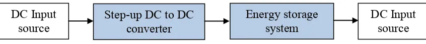
1.5 Scope of Research Work
The scope of this research work will cover two parts from the harvesting circuitry
system, namely the step-up DC to DC converter and the energy storage system. This can
be seen in Fig 1.1.
Figure 1.1 The research scope.
This research is limited to focus on the design of the DC to DC converter, which
has the ability to boost the low input voltage within range of 0.1 V upto 0.75 V to the
higher output voltage and then be stored into an energy storage system, which is
represented by the super capacitor.
The input of the DC to DC converter is from the harvested rectified sources,
which are known to be low voltage; typically less than 1 V. Thus, in order to reduce the
power losses, the component selection is crucial to ensure that the output power from the
DC to DC converter is still sufficient to power up the low power applications.
1.6 Organisation of the Research work
Chapter 1 contains the motivation for the work and the main contributions to the
field. The objectives as well as the project scope are also presented to give an overview
of the research.
Chapter 2 gives more details on the literature work in a broader context. The
chapter reviews past literature on energy harvesting, basic AC to DC converter circuit
and the selection of the DC to DC converter as well as the energy storage system
comparison.
Step-up DC to DC
converter Energy storage system DC Input