SIMULATION DESIGN ON WATER FLOW CONTROL
SYSTEM
NOORSHAHIRAH BT. MASAT
B051010106
UNIVERSITI TEKNIKAL MALAYSIA MELAKA
UNIVERSITI TEKNIKAL MALAYSIA MELAKA
SIMULATION DESIGN ON WATER FLOW CONTROL SYSTEM
This report submitted in accordance with requirement of the Universiti Teknikal Malaysia Melaka (UTeM) for the Bachelor Degree of Manufacturing Engineering
(Robotics & Automation) (Hons.)
by
NOORSHAHIRAH BT MASAT B051010106
880816045198
DECLARATION
I here y, de lared this report e titled “i ulatio Desig o Water Flow Co trol “yste is the results of my own research except as cited in reference.
Signature : ... Author’s Name : ...
APPROVAL
This report is submitted to the Faculty of Manufacturing Engineering of UTeM as a partial fulfillment of the requirements for the degree of Bachelor of Manufacturing Engineering (Robotic & Automation) (Hons.). The member of the supervisory is as follow:
………
ABSTRAK
ABSTRACT
DEDICATION
ACKNOWLEDGEMENT
I would like to thank Encik Mohd Nazmin bin Maslan for being a good supervisor of the project. His extravagant guide, sentient criticisms and patient support the writing of the report in inestimable ways. His support of the project was greatly needed and deeply be pleased about.
TABLE OF CONTENT
2.5.1 Visual Basic 6 Programming Environment (IDE) 14
2.5.2 Animation against Alternatives 15
CHAPTER 3: METHODOLOGY
3.1 Project Flow Diagram 18
3.1.1 Project Planning 20
3.1.2 Theoretical Study 20
3.1.3 Understanding on Simulation System Work 21
3.1.4 Process Planning and Software Selected 22
4.4 Summary 53
CHAPTER 5: CONCLUSION
5.1 Conclusion 54
5.2 Future Works 55
5.2.1 Simulation 55
5.2.2 Hardware 56
REFERENCES
LIST OF FIGURES
3.2 Monitoring simulation system flow chart 22
3.3 Process planning 23
4.9 Mathematical equation in programming 37
4.10 PictureBox programming 38
4.11 TextBox Programming 39
4.12 CommandButton programming 39
LIST OF TABLES
4.1 Description component in Form1 30
LIST OF ABBREVIATIONS, SYMBOLS AND
NOMECLATURE
BASIC - Beginners All-Purpose Symbolic Instruction Code
FKP - Fakulti Kejuruteraan Pembuatan
GUI - Grapichal User Interface
IDE - Integrated Development Environment
PC - Personal Computer
PID - Proportional, Integral, Derivative
PSM - Projek Sarjana Muda
VB - Visual Basic
CHAPTER 1
INTRODUCTION
This chapter covers on the introduction, problem statement, objective and scope of the research study. The introduction discusses the overview about the project that will be conducted. The problem needs to be found before starting the project is identified in the problem statement section. Lastly, the objective is about the target to be achieved with this project meanwhile the scope is project limitation of the project.
1.1 Overview of the Project
At the university, the application of the water flow control system is usually used in water flow and level control system. It is can be used in learning the basic control system so that the student able to know about the connection between water flow control in process control system. This project is about the simulation design on water flow control system. It uses Visual Basic (VB) to show the water movement and the Graphical User Interface (GUI) as the monitoring system interface using the Visual Basic 6 (VB6) software.
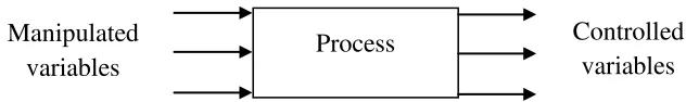
physical or a series transformation in which fluid is converted into a more useful state. A process forms part of a set of production or processing functions complete in and by means of process hardware such as tanks, pipes, fittings, measuring device and others. The performance of an industrial process is influenced by internal and external condition called process variables such as flow, level, temperature, dimension, speed, volume and others. The control of the process variable is archived by the control equipment and the controlling them to the desire level called set points. Figure 1.1 shows the process control variables where the manipulated variables determine the control that state of the system the examples flow rate. The flow rates entering or leaving the process so the control will be changed. The controlled variable there is an associated manipulated variable; it is maintained despite any disturbance.
Figure 1.1: Process control variable (Singh, S.K, 2012)
Visual Basic was developed by Microsoft to extend the capability of BASIC by adding objects and programming like buttons, menus, and other elements of the GUI. VB can also be used within other Microsoft software to program small routine. Programs are commonly referred to as software. Software is essential to a computer because it controls everything the computer does. All of the software is used to make the computers useful is created by individuals working as programmers or software developers. A programmer, or software developer, is a person with the training and skills necessary to design, create, and test computer programs.
Process Controlled
variables Manipulated
1.2 Problem Statement
The problem statement of the project needs to be identified in order to perform the project. Through meticulous observation, it is found out that engineering student lack of a learning kit that can aid them to understand the basic process control system. This simulation is developing as guidance on how to manipulate the process control system using the water level and flow control system. The programming is required to operate the simulation animation using VB6 and to integrate the GUI and animation with their programming lines.
1.3 Objective
A project must have the objective to ensure the project can achieve the target and Gantt chart. The main objective of this project is to create the Graphical User Interface (GUI) with simulations using the Visual Basic software. The other objectives that support it are:
1. To demonstrate the systems in water flow system; open-loop control system and closed-loop control system.
2. To control the water flow in the system for the required process control.
1.4 Scope
created in visual basic 6. This simulation system allows student understanding about how to control the water flow control system.
1.5 Summary
CHAPTER 2
LITERATURE REVIEW
The literature review is done to gain the information on the project that is being carried. Firstly the explanation of water flow followed by process control fundamental, component are related to flow control of fluid, fluid flow fundamental and GUI monitoring system that allows to control the tank.
2.1 Fluid Flow Control System
In fluid flow control system, the water must be controlled continuously and accurately during treatment. Various methods of water flow control can be used. The valves can be the set to allow specific flows of water through a treatment plant either an inlet or the outlet. If the regulating valve is fitted, it will require regular adjustment to ensure that constant flow maintains.
Flow measurement gives an indication of the efficiency of a process. Water flow rate is the important measurement in fluid flow. The water flow is the amount of water passing through a pipe within a given period of time. The flow in pipes under pressure or in open channels under the force of gravity, the volume of water flowing past any given point in the pipe or channel per unit time is called the flow rate or discharge (Q). The water flow rate can calculate using equation velocity multiply cross section vector area to get the volume of fluid passing given station per unit time (Esposito, A , 2009).
2.2 Process Control System
Process control is the control of a physical variable within a particular system. By controlling a particular physical variable, it controls the entire process. Process control allows manufacturer to obtain a higher level of quality control and to conform to stricter safety requirement, creating better products and protecting the safety of workers and consumers. Manufactures need to control the manufacturing environment in order to produce uniform product. Many chemical reactions are dependent on very specific reaction conditions. For safety reasons, manufacturers often need to control physical variable of processes (Singh, S.K, 2012).
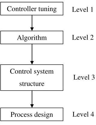
The benefit of process control system has increased production level or in other word productivity, reduces the raw material costs; improve product quality and uniformity of the manufactured goods and services, increased efficiency, improved profitability, increased safety in operation environmental condition and comfort and convenience of operation. There are four levels of process control systems. The level process is shown in Figure 2.1 below (Singh, S.K, 2012).
Figure 2.1: Process control system level (Singh, S.K, 2012).
In level 1, it is controlled tuning to determining the values of controller tuning constants that give the best control. For level 2 is algorithms, it is deciding the type of controller to be used in example P, PI, PID or others. The level 3 is a control system structure, it is determining what to control and manipulate and how to match one controlled variable with one manipulated variable or in other word pairing. The last level is level 4 for process design; it is developing a process flow sheet and using the parameters that produce an easily controllable plant (Singh, S.K, 2012).