SEAT MONITORING SYSTEM
ROHZAINA BINTI ZAINAL
This report is submitted in partial fulfillment of the requirements for the award of Bachelor of Electronic Engineering (Industrial Electronics) With Honours
Faculty of Electronic and Computer Engineering Universiti Teknikal Malaysia Melaka
BORANG PENGESAHAN STATUS LAPORAN PROJEK SARJANA MUDA II
Tajuk Projek : SEAT MONITORING SYSTEM Sesi
Pengajian : 2008/2009
Saya ROHZAINA BT ZAINAL mengaku membenarkan Laporan Projek Sarjana Muda ini disimpan di Perpustakaan dengan syarat-syarat kegunaan seperti berikut:
1. Laporan adalah hakmilik Universiti Teknikal Malaysia Melaka.
2. Perpustakaan dibenarkan membuat salinan untuk tujuan pengajian sahaja.
3. Perpustakaan dibenarkan membuat salinan laporan ini sebagai bahan pertukaran antara institusi
pengajian tinggi.
4. Sila tandakan ( √ ) :
SULIT*
(Mengandungi maklumat yang berdarjah keselamatan atau kepentingan Malaysia seperti yang termaktub di dalam AKTA RAHSIA RASMI 1972)
TERHAD* (Mengandungi maklumat terhad yang telah ditentukan oleh organisasi/badan di mana penyelidikan dijalankan)
TIDAK TERHAD
Disahkan oleh:
__________________________ ___________________________________
(TANDATANGAN PENULIS) (COP DAN TANDATANGAN PENYELIA)
Alamat Tetap: 154-3, Batu 2 3/4
Klebang Kecil,
75200 MELAKA
“I hereby declare that this report is the result of my own work except for quotes as cited in the references.”
Signature : ………
“I hereby declare that I have read this report and in my opinion this report is sufficient in terms of the scope and quality for the award of Bachelor of Electronic
Engineering (Industrial Electronics) With Honours.”
Signature : ………
ACKNOWLEDGEMENT
IJK ١ M ١ NOPQR ١ IۑPQR .
This thesis is the result of months of research, countless effort, and a little pain. The fact that this thesis is the completion of my Bachelor of Electronic Engineering (Industrial Electronics) with Honours, I actually became fond of sensor based technology.
I, hereby, would like to express my deepest gratitude for the ones who had helped me during the whole 2 semesters. I would like to think the reason I have been successful in completing this project is because of the non-stop guides, lesson and motivation that I gained from my project supervisor; Puan Hazura Haroon, my fellow housemates and classmates, and foremost to my dear family.
Not least, my appreciation goes to the proud Faculty of Electronics Engineering and Computer Engineering of Universiti Teknikal Malaysia Melaka.
ABSTRACT
ABSTRAK
CONTENT
CHAP ITEM PAGE
PROJECT TITLE i
DECLARATION ii
DEDICATION iii
ACKNOWLEDGEMENT iv
ABSTRACT v
ABSTRAK vi
CONTENT vii
LIST OF TABLES x
LIST OF FIGURES xi
LIST OF APPENDICES xiii
I INTRODUCTION
1.0 Overview 1
1.1 Objective 2
1.2 Problem Statement 2
1.3 Scope of Work 2
1.3.1 Chair 3
1.3.2 Flexible bend sensor 4
1.3.3 Temperature sensor 5
1.3.4 PIC #1 6
1.3.5 RF Transmitter 6
1.3.6 RF Receiver 6
1.3.7 PIC #2 7
1.3.8 LCD 7
II LITERATURE REVIEW 10
2.0 Prologue 10
2.1 Basic of Wireless Sensor Networks 11
2.2. Strain and Stress 13
2.2.1 Load-Cell Sensor 14
2.2.2 Flexible Bend Sensor 16
2.3 Heat and Temperature 18
2.3.1 Thermal Sensor 18
2.3.2 Thermo-Mechanical Transduction 19
2.3.3 Thermocouple 19
2.3.4 Resonant Temperature Sensor 19
2.3.5 Thermoresistive Effects 20
2.3.6 Temperature Sensor LM35 21
2.4 Microcontroller 22
2.5 Radio Frequency 24
2.5.1 Linx Technology 25
2.5.1.1 Transmitter Module 25
2.5.1.2 Receiver 25
2.5.2 Zigbee™ Technology 28
2.5.3 Cytron Technology 30
2.5.3.1 Transmitter Module 30
2.5.3.2 Receiver Module 31
2.6 AND Gate DM74ALS08 32
III METHODOLOGY 33
3.0 Prologue 33
3.1 Circuitry Design 33
3.1.1 Transmitter Circuit 33
3.2 Software development 35
3.2.1 Proteus 7 35
3.2.2 PIC-Compiler 36
3.3 Hardware Development and Testing 37
3.3.1 Flexible Bend Sensor 39
3.3.2 Testing Temperature Sensor 39
3.2.3 Analogue and Sensor Interfacing 40
IV RESULT AND DISCUSSION
4.1 Circuit Diagram Designation 42
4.1.1 Flexible Bend Sensor Circuit 42
4.1.2 Temperature Sensor Circuit 45
4.1.3 Transmitter Circuit 46
4.1.4 Receiver Circuit 47
4.2 Programming Flow Chart 48
4.3 Hardware Design 51
V CONCLUSION AND SUGGESTION
5.0 Conclusion 53
5.1 Suggestions 53
LIST OF TABLES
NO TAJUK PAGE
2.1 Measurements for Wireless Sensor Networks 12 2.2 Comparison of Temperature Sensor of LM Series 21 2.3 Specification of Cytron Transmitter Module 31 2.4 Specification of Cytron Transmitter Module 32
3.1 AND Gate Function 41
4.1 Result for Testing Flexible Bend Sensor 45
LIST OF FIGURES
NO TITLE PAGE
1.1 System Block Diagram 3
1.2 Chair with cushion padding 4
1.3 Flexible Bend Sensor 4
1.4 Bending the Flexible Bend Sensor 5
1.5 LM35DZ 5
1.6 PIC 16F877A and RF Module 7
2.1 Physical form of strain gauge 13
2.2 Bridge circuit for strain gauge use 14
2.3 Wheatstone Bridge Circuit 15
2.4 Variable Deflection Threshold Switch 17
2.5 Resistance Vs Temperature for NTC Thermistor 20
2.6 Basic Centigrade Temperature Sensor 22
2.7 Bottom view of LM 35DZ 22
2.8 Processor program execution 23
2.9 PIC 16F877A Pinout 23
2.10 HP-3 Series Transmitter Block Diagram 25
2.11 HP-3 Series Receiver Block Diagram 27
2.12 Home and Diagnostics Zigbee™ Examples 29 2.13 Freescale Zigbee™ MC 1321x Block Diagram for
Sensor Application 29
2.14 Transmitter Module 30
2.15 Receiver Module 30
2.16 DM74ALS08 Connection Diagram 32
3.1 Transmitter Circuit 34
4.2 Variable Resistance Reading of Flexible Bend Sensor 43
4.3 Basic Circuit of Flexible Bend Sensor 44
4.4 Flexible Bend Sensor Simulation Testing 44
4.5 Flexible Bend Testing 45
4.6 Transmitter Circuit 46
4.7 Receiver Circuit 47
4.8 Programming Flow Chart for Transmitter Module 48 4.9 Programming Flow Chart for Receiver Module 49 4.10 Initial State during Circuit Simulation 50
4.11 Low Input during Circuit Simulation 50
4.12 High Input during Circuit Simulation 51
413 Outside View 52
LIST OF APPENDICES
NO TITLE PAGE
A Wireless Sensor Networks 56
B Datasheet LM35 61
CHAPTER I
INTRODUCTION
1.0 Overview
The project is to design a prototype for system that would make monitoring seats availability in a room to be more convenient.
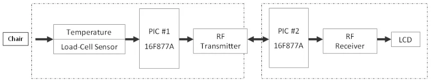
Combination of a flexible bend sensor, a temperature sensor and microcontroller PIC 16F877A are used to detect if a person is sitting on a chair. These sensors are connected to a microcontroller PIC 16F877A that performs ADC conversion. Data transmission would happen to be between an RF transmitter and an RF receiver. LCD (in which is programmed in the microcontroller) will display which seat is occupied or unoccupied.
1.1 Objective
The objectives of this project are to design a wireless seat monitoring system, that should be able to detect person on a seat and consequently, to display the data obtained from the wireless system using LCD. It indicates whether the seat is occupied or unoccupied. In other word, this project is to integrate between hardware and software to build a sensor-based system with application of PIC and wireless RF module.
1.2 Problem Statement
Meeting room, library, lecture hall and tutorial class are always packed with people, and these kinds of rooms offer limited seats. Latecomers who will show up one by one for example, will eventually disturb lecture hall or tutorial class. This could create distraction to the room’s occupant, as the latecomers will scramble to find open seat and if they could not, they groan about not able to find empty seat. As the issue of fact, what matter is when the student outside do not have any idea of the seat availability inside the room. The same goes for meeting room and library, which are regularly filled with people.
This project perhaps could unravel such problem, as it will make it easier and convenient for anyone to check seat availability, via display outside the room. Besides that, it could be positive for everyone in the room.
1.3 Scope of Work
with threshold of 30°C) are sensed by the sensors. These wireless devices will be connected to PIC 16F877A, and through an interface, and accordingly the result of occupied or unoccupied seat will be display via LCD.
[image:18.595.114.548.310.393.2]The limitation of this project is that it cannot display as an occupied seat whenever if a person is idle for more than 15 minutes (for example, gone to the restroom) where the person shall come back to his place.
Figure 1.1 System Block Diagram
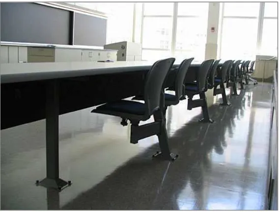
1.3.1 Chair
Figure 1.2 Chair with cushion padding
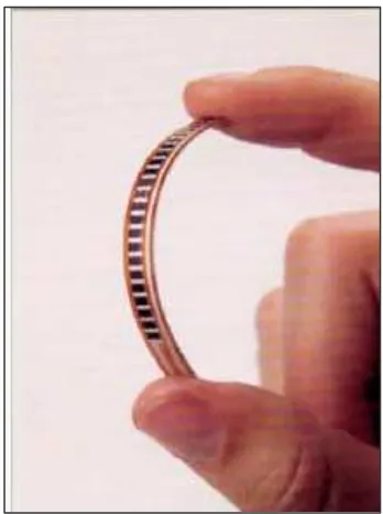
1.3.2 Flexible bend sensor
It senses pressure to determine if a person is sitting on the chair. The threshold pressure is set to be less than 8.5V so that a backpack or something else that is lesser flexing the sensor will not accidentally trigger the operation. Means that, once the microcontroller reads the output voltage to be less than 8.5V, the information from the sensor will then be sent to PIC #1.
[image:19.595.212.439.583.734.2]Figure 1.4 Bending the Flexible Bend Sensor
1.3.3 Temperature sensor
It senses human’s heat temperature to determine if a person is sitting on the chair. The threshold temperature is set to 30°C, which is similarly to normal human body temperature.
[image:20.595.237.445.552.716.2]1.3.4 PIC #1
Microcontroller that is used is 16F877A. It takes the output of the sensors and determine what to do next. Once the chair is activated, the information will be sent by wires to the wireless transmitter. At a predetermined time, the PIC will tell the transmitters and sensors to power on. The power is used to interpret data from the sensors through means of Analog/ Digital conversion. Thresholds will be programmed to determine whether a chair is in use, based on sensor readings.
The transmitter will then take the data and send it over a specific channel, repeating long enough so that the receiver is guaranteed to read the data at least once.
Data transmission will be clocked appropriately so that clock edges match the data rate. After the data is sent, the PIC will power down the rest of the components and stay in standby mode until it is ready to send data again.
1.3.5 RF Transmitter
The transmitter components takes the output from PIC #1 and wirelessly send the information to the wireless receiver. It should send correct data to receiver.
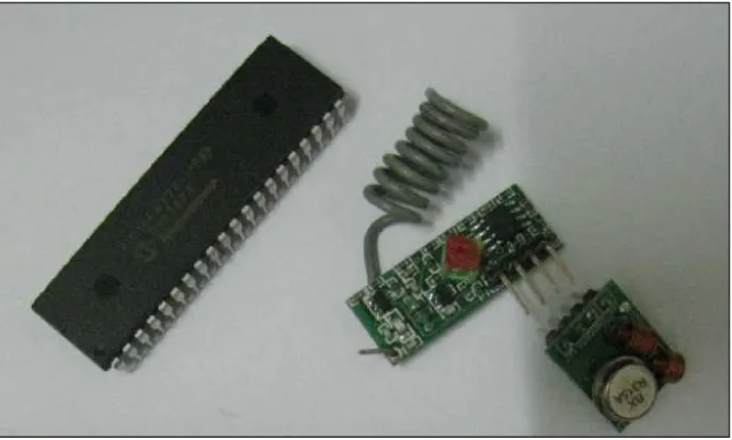
1.3.6 RF Receiver
Figure 1.6 PIC 16F877A and RF Module
1.3.7 PIC #2
PIC 16F877A is the microcontroller used. This component deciphers the information sent by the receiver and outputs the information to the LCD. This PIC is responsible to receive data stream from the receiver and getting the unique ID and information regarding the chair current occupancy.
1.3.8 LCD
LCD displays the data on user-friendly interface. User able to check the seat availability status on the display.
1.4 Methodology
The circuit of this project consists of two main circuits; one for the RF transmitter and the other is for the RF receiver. Transmitter circuit consists of PIC 16F877A, voltage reference circuit, an oscillator circuit, a temperature sensor circuit, a flexible bend sensor circuit, a voltage regulator circuit, two dc sources, and an AND gate IC, and an RF transmitter module. Receiver circuit consists of a PIC 16F877A, voltage reference circuit, an oscillator circuit, a voltage regulator circuit, a dc source and an LCD circuit.
Flow chart of methodology of this project is as described in Chapter 3.
1.5 Thesis Arrangement
This report contains 5 main chapters; Introduction, Literature Review, Methodology, Results and Discussion, and Conclusion.
Chapter І explains project overview, project objectives, problem statement, scope of work, limitations of the project, methods used in the entire project, and thesis arrangement.
Chapter II describes about literature review, which also notify briefly about previous study that was done by other person that is similar to this project. Mechanisms explained in this chapter refer to optional theories and concept that might be compliant in this project. Hypothesis on study of this project is also included in this chapter. Theories and facts as explained, are referred and adapted from articles, journals and some books that are related to the project.
softwares development are also portrayed. The advantages and disadvantages of methods that are chose to be applied in this project are also explained briefly.
Chapter IV tells about Result and Discussion. Overall result and Gantt Chart are included. Outcomes from the project is also been viewed through perspective on objectives and attended problems while accomplishing the project.