WIRELESS HOME ELECTRICAL APPLIANCES MONITORING AND CONTROL USING ZIGBEE
RAZLIN BINTI RAHMAT
This Report Is Submitted In Partial Fulfillment of Requirement for the Bachelor Degree of Electronic Engineering (Wireless Communication)
Faculty of Electronics and Computer Engineering Universiti Teknikal Malaysia Melaka
v
vi
ACKNOWLEGDEMENT
Alhamdulillah, first and foremost, thank to Allah the Almighty for blessing me to complete my Project Sarjana Muda. I would like to enlarge my appreciation to Dr Mohd Saa‟ri Bin Mohamad Isa because of the kindness heart to accept me as one of the student under his supervision. Special thanks also dedicated to his for all comments, idea, and a guideline begin from the first day I start this project.
This appreciation also goes to my friend that gives support, opinion, and advices for me to complete this report especially my friends under Dr Mohd Saa‟ri Bin Mohamad Isa supervision, Nur Naimah Binti Zainal.
To my beloved parents, Rahmat Bin Ahmad and Zainun Binti Yusof, a million of thanks to them who has spending their time, money and advices that never end. Last but not least, thanks to my friends especially from BENW who have been such wonderful friends to me and also to everyone involved in the complete of this project. I would like to thank them for all support and encouragement to me which have given me the courage and wisdom to fulfill my final year project.
vii
ABSTRACT
viii
ABSTRAK
ix
CONTENTS
CHAPTER TITLE PAGE
TITLE i
REPORT VERIFICATION STATUS FORM ii
DECLARATION iii
SUPERVISOR DECLARATION iv
DEDICATION v
ACKNOWLEDGEMENT vi
ABSTRACT vii
ABSTRAK viii
CONTENTS ix
LIST OF TABLE xiv
LIST OF FIGURES xv
LIST OF ABBREVIATIONS xix
x
I INTRODUCTION
1.1 Project Background 1
1.2 Overview 2
1.3 Problem Statement 4
1.4 Objectives 5
1.5 Scope of Project 5
1.6 Thesis Organisation 6
II LITERATURE RIVIEW
2.1 Introduction 7
2.2 Home Automation 8
2.3 Zigbee Technology 9
2.4 Arduino 12
2.5 Relay 13
2.6 Microsoft Visual Studio 14
2.7 Related Work 15
2.7.1 Remotely Controllable Outlet System 15 for Home Power Management
xi Integrated Remote Control
2.7.3 The Jini-based Broadband Power 20 Lie Communication (BPLC) Home
III METHODOLOGY
3.1 Introduction 23
3.2 Project Planning 25
3.3 Project Flow 25
3.3.1 Information Gathering 27 3.3.2 Designing Process 27 3.3.3 Testing and Troubleshooting 28
3.3.4 Redesigning 28
3.4 Conceptual Design 29
3.5 Software and Programming 30 3.5.1 Visual Studio 2012 30 3.5.2 Arduino Software 34
3.5.3 X-CTU 35
3.5.4 Proteuse 7 Professional PCB Design 36
3.5.5 Programming 37
3.6 Hardware Development 38
xii Transceiver
3.6.2 Power module 42
3.6.3 Controlling Box 42
3.6.3.1 Xbee PRO 43
3.6.3.2 Arduino 44
3.6.3.3 Relay 48
3.6.4 Fluorescent Lamps 49 3.6.5 Fan, Study Lamp and Night Lamp 50 3.6.6 Wiring Plug 51 3.6.7 Modified Extension 52
IV RESULT AND DISCUSSION
4.1 Overview 53
4.2 Software 54
4.2.1 Graphical User Interface (GUI) 54
4.2.2 Source code 56
4.3 Hardware 58
4.4 Testing Software 60
4.5 Testing Hardware 67
xiii 4.5.2 Turn On the Night Lamp 68
4.5.3 Turn On the Study Lamp 69 4.5.4 Turn On the Fan 70 4.5.4 Turn On the All The Appliances 71
4.5.5 Turn Off the All The Appliances 72
4.6 Discussion 73
4.6.1 Discussion on Hardware (Relay) 73 4.6.2 Analysis of Output Coding 75 4.6.3 Discussion of Overall Project 78
V CONCLUSION AND RECOMMENDATION
5.1 Conclusion 79
5.1 Recommendation 80
REFERENCES 81
APPENDIX A Graphical User Interface 83
APPENDIX B Data Sheet of X-Bee 89
xiv
LIST OF TABLE
NUM. TITLE PAGE
xv
LIST OF FIGURES
NUM. TITLE PAGE
Figure 1.1 Overview on overall of this system 3 Figure 1.2 Malaysia's electricity consumption (1971-2008) 4
Figure 2.1 Zigbee Series 1 10
Figure 2.2 Topologies of Zigbee 11
Figure 2.3 Arduino Uno 12
Figure 2.4 Relay module 13
Figure 2.5 Remotely controllable outlet systems 16 Figure 2.6 The complete circuit of the BPCOM 17 Figure 2.7 The control flow chart of the MCU program 17
Figure 2.8 IRC structure 19
xvi Figure 2.10 The Jini-based BPLC home control system 21
Figure 2.11 Block diagram of the BPLC home controller 21 Figure 2.12 The Jini surrogate system of the BPLC home 22 control system
Figure 3.1 Smart home appliance phase 23
Figure 3.2 Step of methodology 24
Figure 3.3 Project process flowchart 26 Figure 3.4 Illustration design for the system 29 Figure 3.5 Workspace of Visual Studio 30 Figure 3.6 Flow chart of GUI development 31
Figure 3.7 Log in to the system 32
Figure 3.8 Login success 32
Figure 3.9 Invalid username and/ or password 33 Figure 3.10 Arduino software workspace 34 Figure 3.11 X-CTU software workspace 35 Figure 3.12 Design of circuit in Proteus 36 Figure 3.13 Xbee USB to serial converter 38 Figure 3.14 Block digram of Xv\bee USB to serial converter‟s role 39 Figure 3.15 Flow chart of system turn ON/OFF appliance 40 Figure 3.16 Flow chart of status checking of appliance 41
Figure 3.17 Xbee PRO transceiver 43
xvii
Figure 3.19 X-Bee specification 45
Figure 3.20 Arduino Uno 46
Figure 3.21 Relay module 48
Figure 3.22 Relay connections to Arduino 48
Figure 3.23 Flurescent lamp 49
Figure 3.24 Internal circuit of fluorescent lamp 49 Figure 3.25 Fan, study lamp and night lamp as end devices 50 Figure 3.26 Electrical cable, socket and fuse 51
Figure 3.27 Original extension 52
Figure 3.28 Modified extension 52
Figure 4.1 Graphical User Interface of welcoming the users 54 Figure 4.2 Graphical User Interface of controlling the appliances 55
Figure 4.3 Source code of Arduino 56
Figure 4.4 Source code of Visual Studio 57 Figure 4.5 The Serial port is set up in Visual Studio 12 58 Figure 4.6 Controlling box and modified extension 59 Figure 4.7 Home appliances, modified extension and controlling 59 box
Figure 4.8 Creating account form 60
xviii Figure 4.12 Error notifications for empty password 64
Figure 4.13 Error notifications for empty username 64 Figure 4.14 Successful log in notifications 65 Figure 4.15 Graphical User Interface of controlling the appliances 66 Figure 4.16 GUI control for fluorescent lamp 67 Figure 4.17 Fluorescent lamp turns on 67 Figure 4.18 GUI control for night lamp 68
Figure 4.19 Night lamp turns on 68
Figure 4.20 GUI control for study lamp 69
Figure 4.21 Study lamp turns on 69
Figure 4.22 GUI control for fan 70
Figure 4.23 Fan turns on 70
xix
LIST OF ABBREVIATIONS
APP - Application
GUI - Graphical User Interface
xx
LIST OF APPENDICES
NUM. TITLE PAGE
CHAPTER 1
INTRODUCTION
1.1 Project Background
2 The impact of home automation on domestic lifestyle will be as far ranging as was that of factory automation on industry and its benefits will be available to all sectors of society. Home automation will be achieved not with the household robot but with embedded computing power and memory within dozens of pieces of domestic equipment, each will communicate with the user and with other equipment. PC-Based control is a new way of control related to industrial equipment. Its importance has been increasing remarkably in the last few years because industry‟s need to find new solution for increasing productivity and replacing the traditional control equipment with newer solutions that can take advantage of the latest technologies.
Some of the benefits that PC Control is bringing compared to the traditional systems are lower overall costs, independence from proprietary control systems, easiness to integrate logic, motion, process control and fieldbus systems, and the integration of control and HMI in a single hardware platform.
1.2 Overview
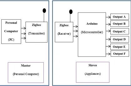
Wireless home system is a 1-ways communication system that can transmit data from the PC to the electrical appliances. The data can be transmitted and received by using a network, X-Bee. The X-Bee will be connected to the PC and be as a master or main point. The electrical appliances also will be attached to the X-Bee and be as slaves.
3
In this project, the PC as a master will show the status of the electrical appliances. With that, user will be able to monitor the status for each appliance. User may switch off the unnecessary appliances by clicking the button on the screen. As the PC is attached to the Bee, data is send through the data communication with the X-Bee at the slaves.
The microcontroller at the slaves which connect between the X-Bee and the appliances will received the command and send it to the corresponding appliance. Then, the appliance will follow the command from the master either to send back the power of the appliance or to change the status.
4
1.3 Problem Statement
The consumption habits of modern consumer lifesyles are causing a huge worldwide waste problem. At present, the overused of power become a big issue. As the switch on, a lot of electrical appliances either at the house, working place or anywhere, usually contributed to the released of carbon dioxide which is one of the harmful gases to the environment. This gas will cause to the greenhouse effect.
The consumption of electricity in Malaysia rises rapidly every year, with an average of 2,533 GWh per year. The electricity consumption, for instance, in 1971 was 3,464 GWh and 94,278 GWh in 2008. By 2020, Malaysia‟s electricity consumption is expected to increase by about 30% from its present value to 124,677 GWh.
Figure 1.2 Malaysia's electricity consumption (1971-2008)