ii
DESIGN AND DEVELOPMENT OF LEAD-THROUGH PROGRAMMING METHOD USING LOW COST INCREMENTAL ENCODER FEEDBACK
SAMEH MOHSEN OMER KANZAL
A report submitted as a partial fulfillment of the requirements for the degree of Mechatronics Engineering
Faculty of Electrical Engineering
UNIVERSITI TEKNIKAL MALAYSIA MELAKA
i
“ I hereby declare that I have read through this report entitled “DESIGN AND DEVELOPMENT OF LEAD-THROUGH PROGRAMMING METHOD USING LOW COST INCREMENTAL ENCODER FEEDBACK” and found that it has complied the partial fulfillment for awarding the degree of Bachelor of Electrical Engineering (Mechatronics)
Signature: ...
Supervisor’s Name: DR. MUHAMMAD FAHMI BIN MISKON
iii
I declare that this report entitled “DESIGN AND DEVELOPMENT OF LEAD-THROUGH PROGRAMMING METHOD USING LOW COST INCREMENTAL ENCODER FEEDBACK” is the result of my own research except as cited in the references. The report has not been accepted for any degree and is not concurrently submitted in candidature of any other degree.
Signature:………
Name: Sameh Mohsen Omer Kanzal
iv
DEDICATION
I would like to express my gratitude to my supervisor: DR. MUHAMMAD FAHMI BIN MISKON for his sincere guidance along my project. I would also like to thank my panels and lecturers for their continuous contributions that made this project possible.
v
ABSTRACT
vi
ABSTRAK
vii
TABLE OF CONTENTS
CHAPTER TITLE PAGE
SUPERVISOR'S ENDORSEMENT i
TITLE PAGE ii
DECLARATION iii
DEDICATION iv
ABSTRACT v
ABSTRAK ix
LIST OF TABLES ix
LIST OF FIGURES x
LIST OF APPENDICES xii
1 INTRODUCTION 1
1.0 Overview 1
1.1 Motivation 1
1.2 Problem Statement 3
1.3 Objectives 4
1.4 Scope 4
2 LITERATURE REVIEW 5
2.0 Overview 5
2.1 Theoretical Background 5
viii
2.3 Lead-Through Programming Method 9
2.3.1 Lead-Through Problems 9
2.3.2 Available Solutions 11
2.4 Summary and Conclusion 18
3 METHODOLOGY 20
3.0 Overview 20
3.1 Lead-Through Programming Method 20
3.2 Experiments 23
3.2.1 Experimental Equipment and Parameters 23
3.2.2 Experimental Set Up 23
3.2.3 Procedures 25
3.2.4 Precautions 31
3.3 Methods of Analysis 31
4 RESULTS AND DISCUSSION 33
4.1 Record and Play-Back Stages Comparison 33
4.2 Errors and Accuracy 39
4.3 Precision and Repeatability 42
5 CONCLUSION AND RECOMMENDATION 44
5.1 Conclusion 44
5.2 Future Work and Recommendation 45
REFERENCES 46
Appendix A 48
ix
LIST OF TABLES
Table Title Page
2.1 Comparison of the Available Solutions in the Lead-Through Programming Method
18
3.1 Arduino Due Specification 26
3.2 Geared Dc Motor Specification 27
3.3 Mdd10a Motor Driver Specification 28
4.1 Motor One Error And Accuracy 40
4.2 Motor Two Error And Accuracy 41
1 Motor One, Record Stage 48
2 Motor One, Play-Back Stage 49
3 Motor Two, Record Stage 50
x
LIST OF FIGURES
Figure Title Page
1.1 World Annual Supply of Industrial Training by Region 2009-2013 2
2.1 Robotic Systems Block Diagram 5
2.2 Robots Programming Methods 7
2.3 Flow Chart of the Data Record Process 9
2.4 Four Major Operational Sequences for the Lead-Through Teaching 12 2.5 Graphical User Interface on Teaching Pendant to Assist Jogging 12 2.6 General Process of Teaching Robot with Robot-Puppet 13
2.7 Lead-Through and Path Learning 14
2.8 Results from Path-Learning 15
2.9 Learned Path Record (Right) and Post Processed Path (Left) 16
2.10 A 3-D Display of A Learned Path 16
2.11 Display of The Contacting Force During the Controlled Motion 17
3.1 Lead-Through Schematic System Diagram 21
3.2 Lead-Through System Design 22
3.3 Planned Experimental Setup 24
3.4 Real Experimental Setup 25
3.5 Constructed Circuit 26
3.6 Experimental Procedures 30
4.1 Generated Trajectories Comparison, Motor One 34
4.2 Generated Trajectories Comparison, Motor Two 35
4.3 Recorded Trajectory 36
4.4 Played-Back Trajectory 37
4.5 Record Stage, to the Left, and Play-Back Stage, to the Right, at Second One
37
xi
Second Two
4.7 Record Stage, to the Left, and Play-Back Stage, to the Right, at Second Three
38
4.8 Record Stage, to the Left, and Play-Back Stage, to the Right, at Second Four
38
4.9 Record Stage, to the Left, and Play-Back Stage, to the Right, at Second Fife
39
4.10 Normal Bell Curve, Motor One 42
4.11 Normal Bell Curve, Motor Two 43
xii
LIST OF APPENDICES
APPENDIX TITLE PAGE
A Detailed Tables and Figure of both Stages 36
1
CHAPTER 1
INTRODUCTION
1.0Overview
This chapter includes motivation regarding the continuous evolution of robotics existence in a diverse of fields, occurrence of lead-through programming method, Problem statement, objectives of this paper and the scope along with the expected limitations of the project.
1.1 Motivation
2
Figure 1.1: World Annual Supply of Industrial Training by Region 2009-2013 [2]
Motion planning problem is the main concept that hooks robots developers’ concern, this type of planning is known as a trajectory generation. Recently, a diversity of human-friendly robots and partner robots have been developed for the aim of interaction between human and robots in various fields. These robots require intelligent capabilities to support the human-robot interactions [3].
On the other hand, many people are afraid that robots are replacing the human being jobs. But in fact they are relieving humans from various tedious, routine and even dangerous jobs. One of the widely spreading jobs that are being taken over by robots is welding process, as robots have recently replaced human in such jobs, as they are considered extremely hazardous, in terms of noise, intense generated heat and ultraviolet light form the welding torch [4]. As a consequence of the above mentioned various applications used, where robots are implemented in, robots and their motion planning, termed as a trajectory generation, have been given a remarkable attention and undetached part of human being daily life.
well-3
experienced with robotic systems’ basic knowledge has gained a non-deniable concern. Based on that need, a new trajectory generation method was proposed on 12th of August 1994 by Timothy L. Graf, lead-through teaching method [14]. It relied on the concept that the operator moves the robot and meanwhile it records the motion data and then saves it for a further playback of the same motion applied by the operator. By applying this method to the field of robotic systems trajectory generation industries, the affordability, feasibility and even efficiency will be ensured. Moreover, it gave the robots a sense of human as they detect the motion and then play it back without any effort from the operator during the playing back mode.
1.2 Problem Statement
4
SMEs’ operators. i.e. the operator in such a programming method is required to only deal with simple switches and physical movement of the end effector.
1.3Objectives
The objectives of this project is to:
i. Design and develop a lead-through programming method for a robotic arm that can record the initial and final positions, save them and then repeat them as accurately as possible.
ii. Analyze the performance parameters of the lead-through programming systems in terms of error, accuracy, encoders' pulses detection-speed and precision.
1.4Scope
This project develops a trajectory generation using a lead-through programming method for robotic systems used in SMEs (Small and Medium Enterprises). The project aims to produce a prototype of a robotic arm with two DOF (degree of freedom) that is able to record the initial and final position of the end effector as moved by the operator and then play it back when required. The performance of the designed system is discussed in terms of error, accuracy, encoders' pulses detection-speed and precision. For the experiment and analysis, an Arduino DUE controller is used to interface the developed system and control the trajectory of the arm based on the motion of the operator. The results of this project is a robotic arm moved manually to a desired final position (Qrec) and
5
� (t) �(t) �(t)
CHAPTER 2
LITERATURE REVIEW
2.0Overview
This chapter contains theoretical background of the trajectory generation, methods of trajectory generation, lead-through programming method and its problems along with the available proposed solutions and the summary of the solution related to the proposed idea in this project.
2.1 Theoretical Background
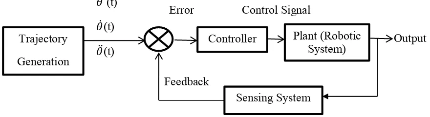
Figure 2.1 shows a schematic of a robotic system in general.
Figure 2.1: Robotic Systems Block Diagram Trajectory
Generation
Error
Controller
Control Signal
Plant (Robotic
System) Output
6
Robots programming has gained an undeniable concern for the few past years, due to their daily corporative and interactive applications offered to their users and operators.
According to [5], trajectory refers to a time history of position, velocity and acceleration for each degree of freedom. The term trajectory generation is not only generating a path for a tool frame to be located within a tool frame, but also includes the human interface issue with the robot’ path specification [5]. For example, if an operator wants to change the location of the robot within a specific space then he may want to be able to specify nothing more than the location and orientation of the end effector and then let the system decide the other information required for that motion, such as duration, velocity and other details.
By assuming the motion of the manipulator is considered as a tool frame, T, and its space is the station frame, S, then the trajectory generation is, in general, changing the position and orientation of the tool frame from an initial value, Tinitial, to an end value,
Tfinal, relative to the station frame [5].
In some applications, it is vital to specify the motion of the tool frame in more details. For example specifying the sequence of the desired via point (intermediate points between the initial and final position). These via points are considered as a set of intermediate points carry out the position and orientation information of the tool-frame relative to the station-frame [5].
For further elaboration, most of robotic systems have a common block diagram, shown in figure 2.1, which explains and illustrates the system general input and output and then the sub-blocks which include the processes involved in both input and output.
As mentioned above robots programming has been given much attention. Recently robots have been involved in most of nowadays activities, such as industrial, human services, and even rehabilitation systems. For these reasons a pathway for robots is vital to be studied and determined as well as the human interface issue which indicates how the robotic system does receive its pathway from human.
7
Spatial: the orientation and location of the end effectors, and how accurately they reach their destination.
Time: how long the end effectors take to reach their desired destination.
Smoothness: identifies whether the robotic system vibrates while moving from the initial to the final station-frame. And how smooth its motion is. For the purpose of solving such relevant issues many studies have been introduced to contribute to this field. Below are some of these studies, introduced in details.
2.2 Methods to Generate a Trajectory
As shown in Figure 2.2, in [6] robots programming methods are divided into three main categories, despite the fact that over 90% of the robots are programmed using the first method, teach method, lead method and off-line programming.
Figure 2.2: Robots Programming Methods [6] Robots Programming
Methods
8
Teach Method, On-Line
The program is generated using either a menu-based system or a text editor. The main characteristic of this method is that the robot is thought how to change its position and/or orientation in a number of different co-ordinate systems to a desired location. This method of programming is simple to be implemented when simple movements are required, but its main disadvantage is that the robot will be out of service during the programming session. Example of teach method is Tiji trajectory generation [7].
Off-Line Programming Method
This method is similar to the teach method in terms of the program build up, except that there are additional tools used to process the CAD (Computer Aided Design) data of the components and generate a sequence of information to be processed. The advantages of this method over the other methods are as follows:
i. Reduce the programming time. ii. Makes the programming easier.
iii. Enables concurrent engineering and reduces product lead time. iv. Allows process optimization.
An example of a trajectory generation using off-line programming is in [8].
Lead Method
9
2.3 Lead-Through Programming Method
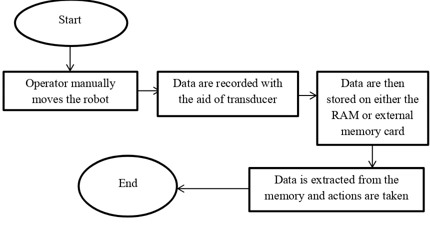
Figure 2.3 illustrates the process of recording data where the operator moves the robot manually by either using one of the interface devices, mentioned below in the problems section, or moving it physically. During the robotic system movement, the transducers attached to the system record the movement’s data and store it in either RAM or external memory card for further processing. As a final stage, the data recorded will be processed for the trajectory generation.
Figure 2.3: Flow Chart of the Data Record Process
2.3.1 Lead-Through Programming Problems
There are four known problems with the lead through method which are (1) affordability, (2) intuitiveness and teaching accuracy of the teach-pendant interface as a human machine interface (HMI), (3) feasibility of the on-line programming due to the great number of the teaching points and (4) the confidentiality and intellectuality of the sensor-less systems especially when path precision is taken into consideration.
Operator manually
moves the robot Data are recorded with the aid of transducer stored on either the Data are then RAM or external
memory card
Data is extracted from the memory and actions are taken Start
10
The first problem can be described in terms of changing the robotic arms’ location and orientation. It is desirable to move the robotic arm’s tool frame rather than moving the space frame itself, for such changes in locations and orientations maneuvering robots using a keypad of joystick on the pendant is not easy and affordable to all operators, as it requires a non-deniable amount of skills and experiences [9].
The second problem is regarding the teach-pendant which is one of the most common ways for programming a robot as well as a common human machine interface (HMI) [10]. Yet to program a robot using a teach pendant, the operator should set up the robot’s jogging conditions, frame and motion mode, only then he can use the joystick of the teach pendant to move the robot [6]. In comparison with the off-line programming methods, programming a robot with a teach pendant does not need a PC, which is an advantage in terms of cost. Yet a teach pendant programming method is not intuitive and has a low teaching accuracy which requires rounds and rounds of trails and errors, hence it is a time consuming and requires a certain level of robotics knowledge to deal with a teach pendant [10].
11
Finally yet importantly, the fourth problem is involved in robots that have direct contact with objects they manipulate are called robot force control. With the force control, robots gain one more step towards human nature (feeling or touching). Trajectory generation by the lead-through teaching for force control robots is quite time-consuming process if path precision is considered [12].
According to [12], methods of programming robot paths can be categorized as CAD based and non-CAD based method. CAD-based system is a method where the operator specifies the geometrical entities such as the surface or the edge of the geometry from a CAD model, and then the system will automatically simulate and generate the path in the virtual world. Despite the beneficial features of the CAD drawings, in reality they are neither confidential nor intellectual especially in the foundry industry [12]. As robots in certain situations have to be able to effectively capture the geometrical information of the area or the object they are acting on.
2.3.2 Available Solutions
Based on the previously listed problems, there are four relevant solutions to these problems respectively. (i) Is the usage of the ISD (industrial steering device) which is known as the jogging mouse, (ii) is a 6 DOF (degree of freedom) wire-based programming device, (iii) is an effective teaching method referred as programming by demonstrating (PbD) and (iv) is the addition of a sensing system to the robotic hand.
12
Figure 2.4: Four Major Operational Sequences for the Lead-Through Teaching [9]
Figure 2.5: Graphical User Interface on Teaching Pendant to Assist Jogging [9]
The second solution was proposed in [10] for the second problem. Even though a 6-DOF mouse is an intuitive technology and demands low physical efforts, it was not a simple solution since the calibration between the 6-DOF mouse and robot coordinate system was required. Consequently, a new device to program a robot was introduced, a
Step 1: Remove Nozzle
Step 4: Replace Nozzle
Step 3: Conduct lead-through teaching
![Figure 1.1: World Annual Supply of Industrial Training by Region 2009-2013 [2]](https://thumb-ap.123doks.com/thumbv2/123dok/501318.56310/14.595.110.447.94.291/figure-world-annual-supply-industrial-training-region.webp)
![Figure 2.2: Robots Programming Methods [6]](https://thumb-ap.123doks.com/thumbv2/123dok/501318.56310/19.595.80.528.438.606/figure-robots-programming-methods.webp)