PARAMETRIC STUDY OF ELECTRIC POWER GENERATOR SYSTEM
LUQMAN HAKIM BIN HAMID
SUPERVISOR DECLARATION
“I hereby declare that I have read this thesis and in my opinion this thesis is sufficient in terms of scope and quality for the award of the degree of
Bachelor of Mechanical Engineering (Automotive)”
Signature : ………
Supervisor : Dr. Mohd Azman bin Abdullah Co-Supervisor : En Herdy Rusnandi
PARAMETRIC STUDY OF ELECTRIC POWER GENERATOR SYSTEM
LUQMAN HAKIM BIN HAMID
This thesis is submitted in partial fulfillment of the requirement for Degree of Bachelor in Mechanical Engineering (Automotive)
Faculty of Mechanical Engineering Universiti Teknikal Malaysia Melaka
DECLARATION
“I hereby declare that the work in this thesis is on my own except for summaries and quotations which that been duly acknowledged.”
ACKNOWLEDGMENT
First of all, I would like to express my gratefulness to the great Creator, Allah S.W.T. on completing this undergraduate project successfully.
Besides from the efforts of me, other acquaintances are giving so much encouragement and moral supports on completing this undergraduate project. I wish to express my sincere appreciation to my helpful supervisor, Dr Mohd Azman bin Abdullah and co-supervisor, En Herdy Rusnandi from Faculty of Mechanical Engineering, for all tremendous supports, guides, and motivations during the project are being carried out. Without his supports, this thesis will never be better and complete than this. Other than that, my millions thank also goes for my both beloved parents; Hamid bin Hashim and Zaraha binti Abdul Rahman. Thank you so much for the endless support that they have given me and this thesis will be nothing without their blessings.
Last but not least, the group of people who willingly sacrifice their own quality time for the sake of true friendships, my colleagues, and housemate Noramanina binti Jerimi, Mohamad Adha bin Mohd Pekeh, Fadzlan bin Zulkiply, and Ariffin bin Zulkifli for helping and guiding me and contributing on giving quality ideas, and also my sponsor, Yayasan Pelajaran Johor (YPJ) for sponsoring funds throughout this thesis.
ABSTRACT
ABSTRAK
CONTENT
CHAPTER TITLE PAGE
DECLARATION i
DEDICATION ii
ACKNOWLEDGEMENT iii
ABSTRACT iv
ABSTRAK v
CONTENT vi
LIST OF TABLE ix
LIST OF FIGURE x
LIST OF SYMBOL xiii
LIST OF ABBREVATIONS xiv
LIST OF APPENDIX xv
CHAPTER 1 INTRODUCTION 1
1.1 Background 1
1.2 Problem Statement 3
1.3 Objective 3
1.4 Scope 3
1.5 Thesis Outline 4
CHAPTER 2 LITERATURE REVIEW 5
2.1 Introduction 5
2.2 Electric generator 5
2.3 Measuring instruments 12
2.4 Vibration of generator 13
TITLE PAGE
2.6 Finite Fourier Transform 21
CHAPTER 3 METHODOLOGY 25
3.1 Introduction 25
3.2 Project methodology 25
3.3 Data collection 27
3.4 Data analysis 29
3.5 Measurement instruments 30
3.5.1 DAQ and sensors 30
3.5.2 Ammeter 31
3.5.3 Tachometer 33
3.5.4 Power monitor 35
3.6 Finite Fourier Transform 36 3.7 Project tools and requirement 37
3.8 Summary 37
CHAPTER 4 DATA AND ANALYSIS 38
4.1 Preliminary results 38
4.1.1 Specification of generator 38 4.1.2 Results of RPM for generator 40 4.1.3 Results of power monitor (standing fan) 43 4.1.4 Results of RPM and current for motor starter 44
4.2 Cost of components 48
CHAPTER 5 RESULTS AND DISCUSSION 49
TITLE PAGE
CHAPTER 6 CONCLUSION AND RECOMMENDATION 61
6.1 Conclusion 61
6.2 Recommendation 62
REFFERENCE 63
LIST OF TABLES
NO TITLE PAGE
2.1 The specification of sample electric generator 7 4.1 The specification of Euro Power Generator 39
4.2 The value of RPM for generator 40
4.3 The value of torque for generator 42 4.4 The data of power monitor from standing fan 43 4.5 The value of RPM and current for motor starter 45 4.6 The value of power and torque for motor starter 47
LIST OF FIGURES
NO TITLE PAGE
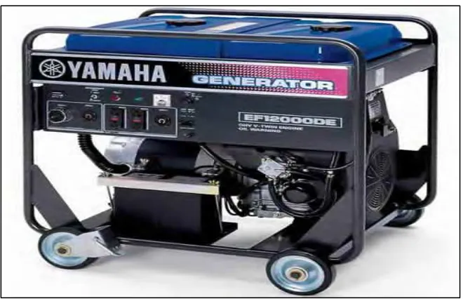
2.1 The sample of electric generator in the market 6
2.2 The parts of electrical generator 8
2.3 Diagram of motor generator set 9
2.4 The principle of magnetostrictive electric generator 9 2.5 (a) Schematic representation of a thermoacoustic machine, 10
(b) Block diagram of the spring-mass subassembly of the mover of the thermoacoustic machine
2.6 The PV power system 11
2.7 (a), (b) The example of vibration waveform 13
2.8 (a) The experiment apparatus, 14
(b) Front view, (c) Side view
2.9 (a) Pre filtered signal, 15
(b) Post filtered signal
2.10 (a) The VIBSCANNER, 17
(b) The reflective tape
(c) The VIBSCANNER on the machine
2.11 (a) The concept design changes, 18 (b) The experimental setup
2.12 Scheme of shaft vibration measurement 19 2.13 Selecting Measurement Points and Directions 20 2.14 An example of FFT spectrum velocity 22
2.15 Principle of Frequency Analysis 23
3.2 The process during vibration experiment 28 3.3 The graph of time and frequency domain 29
3.4 (a) The DAQ sensor, 31
(b) The position of DAQ on generator
3.5 (a) The ammeter, 32
(b) The experiment of current motor stator
3.6 (a) The fluorescent sticker at fin generator, 34 (b) The experiment of measuring RPM generator using tachometer, (c) The fluorescent sticker at fin motor stator,
(d) The experiment of measuring RPM motor stator using tachometer
3.7 (a) The power monitor, 35
(b) The experiment of measuring load standing fan by using power monitor
4.1 The Euro Power Generator 38
4.2 (a) The tachometer, 42
(b) The experiment of measurement RPM
4.3 (a) The experiment with load, 44
(b) The power monitor
4.4 (a) The sample of ammeter, 47
(b) The reading of RPM by using the tachometer, (c) The reading of ampere by using ammeter
5.1 The DAQ on generator 50
5.2 (a) The graph of ax against time, 51 (b) The graph of ay against time,
(c) The graph of az against time
5.3 (a) The graph of pitch against time, 52 (b) The graph of roll againt time,
(c) The graph yaw against time
5.4 (a) The graph of ax with load against time, 53 (b) The graph of ay with load against time,
(c) The graph of az with load against time
5.5 (a) The graph of pitch with load against time, 54 (b) The graph of roll with load against time,
5.6 (a) The graph of ax against frequency, 57 (b) The graph of ay against frequency,
(c) The graph of az against frequency
5.7 (a) The graph of pitch against frequency, 58 (b) The graph of roll against frequency,
(c) The graph yaw against frequency
5.8 (a) The graph of ax with load against frequency, 59 (b) The graph of ay with load against frequency,
(c) The graph of az with load against frequency
5.9 (a) The graph of pitch with load against frequency, 60 (b) The graph of roll with load against frequency,
LIST OF SYMBOL
k = Stiffness of spring m = Mass
c = Stiffness of damper I = Current
f = Frequency P = Power cm = Centimeter kg = Kilogram lbs = Pounds Hz = Hertz v = Volts Amps = Amperes
CC = Cubic centimeter W = Watts
Vpeak = Voltage at peak Emf = Electromotive force mm = Millimeter
s = Seconds kW = Kilo Watts n = Number 2D = 2 Dimensional 3D = 3 Dimensional Nm = Newton meter
LIST OF ABBREVATIONS
FFT = Finite Fourier Transformation RPM = Revolution per Minute
DFT = Discrete Fourier Transform FDTD = Finite Difference Time Domain FT = Fourier Transform
PD = Partial Discharge NG = Nano Generator
DCS = Distributed Control System HP = Horse power
VSCF = Variable Speed Constant Frequency AC = Alternating Current
DC = Direct Current MATLAB = Matrix Laboratory DAQ = Data acquisition HP = Horsepower
LIST OF APPENDICES
NO TITLE PAGE
A Gantt chart of FYP 1 68
B Gantt chart of FYP 2 69
CHAPTER 1
INTRODUCTION
1.1 BACKGROUND
Electricity is one of the most important energy in daily life. Nowadays, in the era of technology, electricity is requirements for every individual person, regardless of ages, region, and gender to survive completely. Electricity gives a wide variety of well known effects, such as lightning, electromagnetic induction, electrical current, and static electricity. Electricity is the set of physical phenomena associated with the presence and flow of electric charge. In addition, the electricity also closely related to permits the creations and receptions of electromagnetic radiation. For example, the sound waves and light waves.
induction whenever a conductor moves relative to a magnetic field and electromotive force (EMF) are induced in this conductor. Especially, if a coil is spinning in a magnetic field, the two sides of the coil is moving in opposite directions. So the voltages are induced between its terminals.
Mostly in Malaysia the generator is used at night market. Usually when the generator is running, the machine will produce a vibration and its own parameters such as power, torque and RPM. The vibration motion of a whole body can be completely described as a combination of individual motions of six different types. These are translated in the three orthogonal directions of x, y, and z axis. For instance, it can rotate lengthwise (roll), rotate around the vertical axis (yaw), and rotate about the port-starboard axis (pitch) moment. Moreover, there are have many types of generator and their specifications. For example single phase power and three phase power. Other than that, the values of voltage, battery, frequency, and engine also closely related to the performance of the generator.
1.2 PROLEM STATEMENT
The problem statement of this project is the generator produces a vibration when running and the value of torque, horsepower and RPM related to the waveforms of amplitude vibration occurs. Moreover, the generator is use a internal combustion engine which is pollution to the environment and green house effect.
1.3 OBJECTIVES
There are several objectives of this project which is to study the vibration of the generator. Then, to analyze the value of torque and RPM for generator and motor starter. Lastly, to determine the relation between torque and RPM of generator.
1.4 SCOPE
1.5 THESIS OUTLINES
CHAPTER 2
LITERATURE REVIEW
2.1 INTRODUCTION
This chapter will go through all about the literature reveiw related study of the project. This chapter are referring to the previous paper of research thesis, journal, conference paper and any media or bulletin to get more understanding about this project. This literature review was helps in finding the concept of electric generator, vibration of the generator, air compressor, power and torque of generator and Finite Fourier Transform (FFT) software. Besides that, this chapter also can define the theory and experiment closely related to all about the power generator system.
2.2 ELECTRIC GENERATOR
nearly all of the power for electric power grids. There are so many brands and products of the electric generator that available in the market. Figure 2.1 shows the sample of electric generator and Table 2.1 shows the required specification which is Yamaha EF12000DE - 9,500 Watt Electric Start Portable Generator (Kevin (2002)).