NUMERICAL ANALYSIS OF THE EFFECTS OF
Kita-13, Nishi-8, Kita-ku, Sapporo, Japan2
Graduate School of Engineering, Hokkaido University Kita-13, Nishi-8, Kita-ku, Sapporo, Japan
Vehicle Testing & Research Department, Mazda Motor Corporation Aki Gun, Hiroshima, 7308670, Japan
5
Vehicle Testing & Research Department, Mazda Motor Corporation Aki Gun, Hiroshima, 7308670, Japan
ABSTRACT : The present study investigated the effects of transient aerodynamic forces on driving stability of road vehicle. The investigation was carried out using large eddy simulation (LES). To facilitate the investigation, two vehicle models with distinct upper body geometries were developed. The models adopted the characteristic geometries of upper body of real sedan-type vehicles with distinct pitching stability behavior. To probe the dynamic response of the models, a forced-sinusoidal-pitching oscillation is imposed on them during the LES. Accordingly, the models undergo pitching oscillation in a similar manner to the rear-ride-height fluctuation of real vehicles. To allow quantitative analysis on the stability characteristic of models, a parameter termed aerodynamic damping coefficient is introduced. The coefficient quantifies the work done by aerodynamic pitching moment on the models during pitching oscillation. For validation of the LES method, flow structures around the models obtained by stationary LES were compared to the wind tunnel measurements. The comparison shows good agreement. Meanwhile, the dynamic LES results show higher aerodynamic damping in the model with rounded front pillar configuration, by about 22.3%. The Underbody has the highest contribution to the total aerodynamic damping, which was up to 69%. However, the difference between the aerodynamic damping of models with distinct front and rear pillar configurations mainly depends on the trunk-deck contribution.
KEYWORDS: damping, pitching, transient, aerodynamics, vehicle, stability, LES, visualization, vortex, sedan, pillar
INTRODUCTION
Conventionally, development of road vehicle aerodynamics is mainly focused on the steady-state component, particularly the drag coefficient, which was obtained through wind tunnel measurement or CFD computation. However, aerodynamics of road vehicle comprises more than that. In real life situation, a vehicle is subjected to various transient aerodynamic forces and moments, which can potentially influence the driving attitude of the vehicle. Hence, except for fuel economic and top speed factors, drag coefficient alone is not adequate to reflect the aerodynamic performance of vehicle. To improve realism in vehicle’s aerodynamic assessment, it is important to take into consideration the dynamic aspect which the vehicle encountered in real life.
In this study, we conducted LES on flow past two vehicle models to investigate the influence of transient aerodynamics on their pitching stability characteristics. During the LES, sinusoidal-forced-pitching oscillation was imposed on the vehicle models to probe their dynamic responses. The computed pitch moment was phase averaged, and decomposed to estimate their aerodynamic damping factors. Then, flow visualization was performed to examine the damping mechanism which causes the difference in the pitching stability behavior of the models.
SIMPLIFIED VEHICLE MODELS
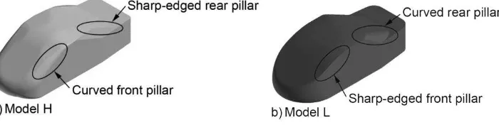
The simplified models are of simple body shapes which represent real sedan-type vehicles of different pitching stability characteristics (Okada, 2009). The models are of similar height H, width W, and length L measurements (210mm x 80mm x 65mm). The main characteristic differences between the models are at the front and rear pillar shapes; Sharp-edged front pillar coupled with rounded rear pillar for model representing the sedan of lower pitching stability, and vice versa (see Fig. 1(a) and (b)). However, both models are having the same slant angles of 30° and 25° for the front and rear pillars, respectively. In order for convenient in the discussions, the vehicle model represents the vehicle of lower pitching stability is designated as
“model A”, while the other model is termed “model B”, hereafter.
Fig. 1: Simplified sedan-type vehicle models
NUMERICAL METHODS
LES Code
The present study carried out the LES computations by the in-house CFD code “FrontFlow
/red-Aero”, which was originally developed under the project “Frontier Simulation Software for Industrial Science”, and optimized for vehicle aerodynamics simulation by Tsubokura et al
(2009a) under the projects “Revolutionary Simulation Software (RSS21)”. The code has been
Governing Equations
The LES solved the spatially filtered continuity and Navier-Stokes equations:
0
of the fluid. The over-bar indicates the spatially filtered quantity. The strain rate tensor Sij are
defined as
the vicinity of solid boundary, Van Driest dumping function fd is used:
225
1 y
d
f e (6)
The governing equations are discretized by using the vertex-centered unstructured finite volume method. The second-order central differencing scheme was applied for the spatial derivatives and blending of 5% first-order upwind scheme for the convection term was exploited for numerical stability. For time advancement, Euler implicit scheme was used. The pressure-velocity coupling was preserved by using SMAC (Simplified Marker and Cell) algorithm.
Computational Domain and Boundary Conditions
The shape of the computational domain is of a rectangular duct, which covered 3.14L upstream of the vehicle model, 6.86L downstream, 4.0W on both sides, and a height of 7.2H. It encompasses of 16 million elements with 5 million nodes. In addition, finer elements are constructed nearby the vehicle models to capture more details of the flow information around the vehicles (see Fig. 2). Fifteen layers of prism mesh are generated from the surface of the vehicle models with the thickness of the first layer being 0.1 mm. The typical wall distance of the first nearest grid point is less than 150 in the wall unit (y+), which is within the logarithmic layer of the mean velocity profile.
Fig. 2: Numerical grid
At the inlet boundary, the approach flow was set to be a constant, uniform velocity of 16.7 m/s, corresponding to Reynolds number, Re of 2.3 x 10⁵ based on the vehicle model length L. At the outflow boundary, zero gradient condition was imposed. The ground surface was divided into two regions in which free-slip wall boundary was imposed to the 3.0L from the inlet to simulate the suction floor effect which prevent the development of boundary layer, while the remaining ground surface was treated by the wall-model assuming a fully developed turbulent boundary layer. As for the surface of the vehicle models, the log-law distribution of instantaneous velocity was imposed. Finally, the ceiling and lateral boundaries of the domain were treated as free-slip wall boundary.
Forced Pitching Oscillation Setting
In order to probe the transient response of the models during pitching, a forced-sinusoidal-pitching oscillation is imposed on the models during LES. This is achieved by employing the Arbitrary Lagrangian-Eulerian (ALE) technique. The axis of rotation is at the location corresponds to where front wheel axle is situated in the case of a real vehicle. The pitch angle θ is defined as θ = θ0 + θ1 sin(2πft). By setting θ0 and θ1 equaled to 2, the vehicle models were
forced to oscillate between 0° to 4°. The frequency f is 10 Hz, which is equivalent to the Strouhal number St of 0.13. Phase-averaged results presented in this paper are the averaged of 15 cycles after the LES computation achieved stable periodic conditions.
RESULTS AND DISCUSSION
Aerodynamic Damping Characteristics
Phase-averaged pitching moment M acting on model A and B during forced-sinusoidal-pitching oscillation is as shown in Fig. 3. It can be decomposed into three parts as, M = Cstat + Csin
sinφ(t)+ Ccoscosφ(t) where, Cstat, Csin, and Ccos are numerical coefficients to be determined by
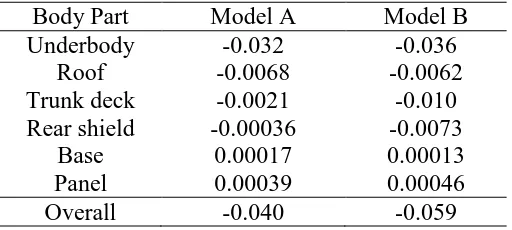
fitting the non-linear function to the M data sets. Since the imposed displacement of the models is given in sine function, thus only the third component has effect on the pitching motion. Details in the derivation of the function are as described by Nakashima et al (2009). Table 1 summarizes the body part contribution and the overall Ccos of the two models. As depicted, the
Ccos values are in a negative sign, thus the work done by M resists the pitching oscillation of the
Fig. 3: Phase-averaged M and their approximations; Model A (Left) and model B (Right)
Table 1: Ccos of models A and B
Body Part Model A Model B Underbody -0.032 -0.036
Roof -0.0068 -0.0062 Trunk deck -0.0021 -0.010 Rear shield -0.00036 -0.0073
Base 0.00017 0.00013
Panel 0.00039 0.00046
Overall -0.040 -0.059
Contribution of Body Parts to Aerodynamic Damping
As summarized in Table 1, the approximated coefficients of the rear shield, roof, base, and body are rather small (by an order of magnitude or two), thus contribution to the dynamic response of the models is mainly depends on the proportion made by the underfloor and trunk deck. Between the two models, percentage difference in the approximated coefficients of the underfloor is only accounted for about 12%, while 132% for the trunk deck. Hence, it can be deduced that the primarily factor that contributes to the different of pitching stability characteristic between the models is trunk deck. The relatively smaller percentage difference in the underfloor can be associated to the same flat underfloor configuration of the models.
CONCLUSIONS
Taking into account the effect of transient aerodynamics, a new index—termed “aerodynamic
-damping coefficient”—is introduced for automotive application. It enables quantitative
ACKNOWLEDGEMENTS
This work was supported by the 2007 Industrial Technology Research Grant program from the New Energy and Industrial Technology Development Organization (NEDO) of Japan. Development of the base software FFR was supported by the FSIS and “Revolutionary
Simulation Software (RSS21)” projects sponsored by MEXT, Japan. The PhD program of the
first author is supported by the Universiti Teknikal Malaysia Melaka.
REFERENCES
Okada, Y., Nouzawa, T., Nakamura, T. and Okamoto, S., "Flow structure above the trunk deck of sedan-type vehicles and their influence on high-speed vehicle stability 1st report: On-Road and Wind-Tunnel Studies on Unsteady Flow Characteristics that Stabilize Vehicle Behavior", SAE Paper 2009-01-0004, 2009.
Nakashima, T., Tsubokura, M., Nouzawa, T., Nakamura, T., Ichimiya, M., “Flow Structures above the trunk deck of sedan-type vehicles and their influence on high-speed vehicle stability, 2nd report: Numerical investigation on simplified vehicle models using
large-eddy simulation”,SAE International Journal of Passenger Cars; Mechanical Systems. Vol. 2-1,
pp. 157-167, 2009.
Tsubokura, M., Nakashima, T., Kitoh, K., Sasaki, Y., Oshima, N. and Kobayashi, T., "Development of an Unsteady Aerodynamic Simulator Using Large-Eddy Simulation Based on High-Performance Computing Technique", SAE Paper 2009-01-0007, 2009a.
Tsubokura, M., Kobayashi, T., Nakashima, T., Nouzawa, T., Nakamura, T., Zhang, H., Onishi, K., and Oshima, N., "Computational visualization of unsteady flow around vehicles using high performance computing", Computers & Fluids, No. 38, pp. 981-990, 2009b.