REMOTE MEASUREMENT OF WEARABLE SENSOR USING ZIGBEE
MUHAMAD FARIQ BIN AHMAD
This Report Is Submitted In Partial Fulfillment Of Requirements For The Bachelor
Degree of Electronic Engineering (Industrial Electronic)
Fakulti Kejuruteraan Elektronik dan Kejuruteraan Komputer
Universiti Teknikal Malaysia Melaka
UNIVERSTI TEKNIKAL MALAYSIA MELAKA
FAKULTI KEJURUTERAAN ELEKTRONIK DAN KEJURUTERAAN KOMPUTER BORANG PENGESAHAN STATUS LAPORAN
PROJEK SARJANA MUDA II
Tajuk Projek :
REMOTE MEASUREMENT OF WEARABLE SENSOR USING ZIGBEE
……… Sesi
Pengajian :
1 2 / 1 3
Saya MUHAMAD FARIQ BIN AHMAD mengaku membenarkan Laporan Projek Sarjana Muda ini disimpan di Perpustakaan dengan syarat-syarat kegunaan seperti berikut:
1. Laporan adalah hakmilik Universiti Teknikal Malaysia Melaka.
2. Perpustakaan dibenarkan membuat salinan untuk tujuan pengajian sahaja.
3. Perpustakaan dibenarkan membuat salinan laporan ini sebagai bahan pertukaran antara institusi
pengajian tinggi.
4. Sila tandakan ( √ ) :
SULIT*
*(Mengandungi maklumat yang berdarjah keselamatan atau kepentingan Malaysia seperti yang termaktub di dalam AKTA RAHSIA RASMI 1972)
TERHAD** **(Mengandungi maklumat terhad yang telah ditentukan oleh organisasi/badan di mana penyelidikan dijalankan)
TIDAK TERHAD
Disahkan oleh:
__________________________ ___________________________________ (TANDATANGAN PENULIS) (COP DAN TANDATANGAN PENYELIA)
iii
“Saya akui laporan ini adalah hasil kerja saya sendiri kecuali ringkasan dan petikan yang tiap-tiap satunya telah saya jelaskan sumbernya”
Tandatangan :………...
Nama Penulis :Muhamad Fariq Bin Ahmad
iv
“Saya/Kami akui bahawa saya telah membaca karya ini pada pandangan saya/kami karya ini adalah memadai dari skop dan kualiti untuk tujuan penganugerahan Ijazah
Sarjana Muda Kejuruteraan Elektronik (Elektronik Industrial)”
Tandatangan :……….
Nama Penyelia :Engr.Hazli Rafis Bin Abdul Rahim
v
DEDICATION
To my beloved parents for the love that arose for me until today
My supporting brothers that never stopped praying for me
And
vi
ACKNOLEDGEMENT
Alhamdulillah, praise to Allah S.W.T for the guidance and blessing best
owed upon me, for without it I would not have been able to come this far.
I wish to thank with appreciation, Engr.Hazli Rafis Bin Abdul Rahim, my
project supervisors for his advice, understanding, well guidance and help throughout
this project. Without his valuable suggestions and encouragement, this project would
have not been successful.
A special thanks to my family especially my parents who encouraged me in
my final year here and gives me lots of inspiration. May Allah S.W.T bless both of
them. Not forgotten to all my fellow friends for their brilliant ideas, support and
encouragement throughout the duration of this project. Thank you all so much.
Lastly, my heartfelt appreciation goes to all, who have directly or indirectly helped
vii
ABSTRACT
Substation is one of the most important parts of power system. The
manual inspection is still used in many substations in Malaysia. Obviously, it is
significant to establish an aid inspection monitoring and positioning system in
substations, which is useful to the inspectors and manager. Thus, this project focused
on Remote Measurement of Wearable Sensor using ZigBee to help user in
monitoring temperature. This project aims to detect the temperature using heat sensor
where is connected to microcontroller to send the data using ZegBee and store in
excel. The main objective of this project is to design a circuit for transmitter and
receiver of ZigBee module. The ZigBee module transmits and receives the data
(temperature) measured by the heat sensor at two condition; normal temperature
condition and at exceeded temperature point. In this project, the smart wireless
temperature data using ZigBee module is introduced for mankind in the future and
viii
ABSTRAK
Pencawang elektrik adalah salah satu bahagian yang paling penting dalam
system penjanaan kuasa. Pemeriksaan manual masih digunakan dalam banyak
pencawang di seluruh Malaysia. Jelas sekali, ia adalah penting untuk mewujudkan
pemantauan bantuan pemeriksaan dan sistem kedudukan dalam pencawang yang
berguna kepada pemeriksa dan pengurus. Oleh itu, projek ini mengenai “Remote Measurement of Wearable Sensor using ZigBee” ini dicadangkan untuk membantu pengguna memantau suhu darirangkaian ZigBee. Projek ini bertujuan untuk
mengukur suhu dengan menggunakan sensor haba dengan menghubungkanalat
elektronik yang kecil seperti litar mikro-pengawal dan menghantar data kepada
Visual Basic dan seterusnya dimasukkan ke dalam Microsoft Excel. Objektif utama
projek ini adalah untuk merekabentuk dan membina litar pemancar dan penerima
yang akan dilaksanakan dengan rangkaian ZigBee. Rangkaian ZigBee digunakan
untuk menghantar dan menerima data (suhu) yang diukur oleh sensor suhu pada dua
keadaan seperti suhu dalam keadaan suhu bilik dan pada ketika suhu telah melebihi
suhu yang ditetapkan. Dalam projek ini, kawalan tanpa wayar bagi menyukat
keadaan suhu menggunakan rangkaian ZigBee diperkenalkan untuk kegunaan
ix
TABLE OF CONTENTS
CHAPTER TOPIC PAGE
PROJECT TITLE i
DECLARATION iii
DEDICATION v
ACKNOWLEDGEMENT vi
ABSTRACT vii
ABSTRAK viii
TABLE OF CONTENTS ix
LIST OF TABLES xii
LIST OF FIGURES xiii
LIST OF ABBREVIATIONS xv
I INTRODUCTION
1.1 Background 1
1.2 Objectives 2
1.3 Problem Statement 2
1.4 Scope of Work 3
1.5 Project Significant 3
II LITERATURE REVIEW
2.1 Introduction To Zigbee 4
2.1.1 Principal Operation of ZigBee 5
2.1.2 Different Types of Topologies 6
2.1.3 Difference between Bluetooth and ZigBee 8
2.2 Liquid Crystal Display (LCD) 8
x
2.2.1.1 Enable (EN) 10
2.2.1.2 Register Select (RS) 11
2.2.1.3 Read/Write (R/W) 11
2.2.2 LCD Screen 11
2.2.3 Interfacing with PIC 13
2.3 Microcontroller 13
2.3.1 Variation of Microcontroller 15
2.3.2 Device Overview 16
2.3.2.1 Product Features 16
2.4 Development Languages 17
2.4.1 Assembly Language (ASM) 17
2.4.2 BASIC 17
2.4.3 C Language 17
2.5 Temperature Sensor- LM35 CZ sensors 18 2.5.1 Specifications of Temperature Sensor- LM35 CZ 18
Sensor
III PROJECT METHODOLOGY
3.1 Phases of Method and Approach 20
3.1.1 First Phase (Literature Review) 22
3.1.2 Second Phase (Design and Simulation) 22
3.1.3 Third Phase (Implementation) 23
3.1.4 Fourth Phase (Thesis Writing) 23
3.2 Collecting Data 24
3.2.1 Etching Circuit 24
3.2.2 Drilling Process 24
3.2.3 Installation the Component 25
3.2.4 Soldering Process 26
xi
IV RESULTS AND DISCUSSION
4.1 Introduction 27
4.2 Functional Block Diagram 28
4.3 Software 28
4.3.1 PIC - Compiler 28
4.3.2 Protues ISIS 7 Professional 29
4.4 Hardware 31
4.4.1 PIC Microcontroller Circuit 31
4.4.2 Connection of Hardware 33
4.4.3 Temperature Sensor (LM35) Functionality Check 34
4.5 Result Analysis 36
4.6 Final Results 38
V CONCLUSION AND RECOMMENDATIONS
5.1 Conclusion 40
5.2 Recommendation 41
REFERENCES 42
xii
LIST OF TABLES
NO TITLE PAGE
2.1 Pin Description 10
4.1 Temperature Vs Time 36
4.2 Time Delay Vs Distance 37
xiii
LIST OF FIGURES
NO TITLE PAGE
1.1 The Architecture of Monitoring System 2
2.1 ZigBee Module 5
2.2 Star Topology 6
2.3 Mesh Topology 6
2.4 Tree Topology 7
2.5 5x8 Character Display 12
2.6 LCD Connection 12
2.7 Interfacing with PIC 16F877A 13
2.8 Block Diagram for Microcontroller 15
2.9 Pin Diagram of PIC 16Fb77A 16
2.10 LM35 CZ Overview 18
3.1 Methodology Flowcharts 21
3.2 Etching Process 24
3.3 Drilling Process on PCB Board 25
3.4 Components Installed on Board 25
4.1 System Structure 28
4.2 Testing Coding Using PIC – Compiler 29
4.3 Simulation of LCD Circuit 29
4.4 Schematic Diagram of PIC Microcontroller Circuit 32
4.5 The PCB Layout 32
4.6 Etched Board from the Top View 33
4.7 Etched Board from the Bottom View 33
xiv
LIST OF FIGURES
NO TITLE PAGE
4.9 Hardware Connection of ZigBEE 34
4.10 Voltmeter Reading for LM35 34
4.11 Example of Temperature Reading for LM35 35
4.12 Hardware Connection of All Devices 35
4.13 Temperature Vs Time 36
4.14 Time Delay Vs Distance 37
4.15 In Normal Temperature 38
xv
LIST OF ABBREVIATION
POR - Power-on Reset
BOR - Brown-out Reset
ASM - Assembly Language
PCB - Printed Circuit Board
LED - Light Emitting Diode
EN - Enable
RS - Register Select
R/W - Read/Write
EEPROM - Electrical Erasable Programmable Random Access Memory
ICD - In Circuit Debugging
A/D - Analog-to-Digital
PWM - Pulse Width Modulation
UART - Universal Asynchronous Receiver Transmitter
WSN - Wireless Sensor Node
LCD - Liquid Crystal Display
PIC - Programmable Integrated Circuit
ISM - Industrial, Scientific and Medical
RAM - Random Access Memory
PAN - People Area Network
CLH - Cluster Head
CID - Cluster Identifier
PC - Personal Computer
RISC - Reduced Instruction Set Computer
LP - Low Power Crystal
xvi
LIST OF ABBREVIATION
HS - High Speed Crystal
RC - Resistor/Capacitor
Rx - Receiver
1
CHAPTER I
INTRODUCTION
1.1 Background
Substation is one of the most important parts of power system. The manual
inspection is still used in many substations in Malaysia. Obviously, the manual
inspection is significant to establish an aid inspection monitoring and positioning
system in substations, which is useful to the inspectors and manager [1].
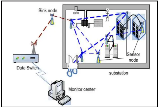
The functions of the system are exactly positioning of staff that entered
monitoring area and real-time monitoring the high-risk work area and non-work area
and timely warning to abnormal behaviour. The system also can record and replay
the inspected track, and avoid careless inspecting occurs as shown in Figure 1.1. The
figure shows that the architecture of the presented system, which mainly includes
three parts this are monitoring centre, WSN communication network and terminal.
The terminal includes three parts this are sensor, sound and light alarm module and
WSN node. Monitoring centre can display data real-timely. In case of emergency,
monitoring centre can control terminal. By combining with the real environment of
the substation, nodes are deployed reasonably in accordance with the principle of
2
Figure 1.1 :The Architecture of Monitoring System.
The terminal is installed in high-risk work area of substation. As it receives “start “command from monitoring centre, the microwave sensor will start to work. In this case, if anyone enters the monitoring area, the terminal will start light and sound
alarm. At the same time, abnormal event will be uploaded to the monitoring centre
and real-time displayed in monitoring system.
1.2 Objectives
To design circuit for transmitter and receiver of ZigBee module.
To measure the smart wireless temperature data using ZigBee.
To analyze the performances of the signal range.
1.3 Problem Statement
Dangerous for inspector since substation is high-risk work area.
Carelessness of inspectors.
Time-consuming since the wide distribution of substations.
3
1.4 Scope of Work
This project focused on measuring of temperature through the
Transmiert-Receiver of Zigbee module and display the result on the user computer. This project
primarily covered the following parts:
The connection between the programmable integrated circuit (PIC) circuits with Zigbee module.
The construction of programmable integrated circuit embedded circuit and LCD circuit.
The construction of programmable integrated circuit embedded circuit and temperature sensor.
The design of command or coding for programmable integrated circuit 16F877A that connected to the Zigbee module.
All the parts above will function in one system that transmitting system will
send the data through the Zigbee module and the receiving system will display the
data on user computer.
1.5 Project Significant
This system can bring awareness to the authorities to the importance of health condition of power transformer.
To help user monitor the temperature using ZigBee network.
CHAPTER II
LITERATURE REVIEW
2.1 Introduction to ZigBee
ZigBee is a wireless network protocol specifically designed for low data rate
sensors and control networks as shown in Figure 2.1. ZigBee is a consortium of
software, hardware and services companies that have developed a common standard
for wireless, networking of sensors and controllers. While other wireless standards
are concerned with exchanging large amounts of data, ZigBee is for devices that
have smaller throughout needs. The other driving factors are low cost, high
reliability, high security, low battery usage, simplicity and interoperability with other
ZigBee devices [3].
Compared to other wireless protocol that ZigBee wireless protocol offers low
complexity. ZigBee wireless protocol also offers three frequency bands of operation
along with a number of network configurations and optional security capability. In
health care, ZigBee can be used for patient monitoring process control, assuring
compliance with environmental standards and energy management. Used correctly,
ZigBee enabled devices can give a warning before a breakdown occurs so that
repairs can be made in the most cost effective manner. They will be used for
controlling our home entertainment systems, lights, garage door openers, alarms,
5
Figure 2.1: ZigBee Module
2.1.1 Principal Operation of ZigBee
ZigBee hardware typically consists of an eight bit microcontroller combined
with a miniature transceiver a small amount (example 32 KB) of flash memory and
RAM. Most of the ZigBee stack is provided in ASIC. ZigBee operates with ISM 2.4
GHz frequency band and is pin for pin compatible with maxstream’s ZigBee product. There are three radio frequencies used for ZigBee radio frequency communications
2.4 GHz with 16 channels and a data rate of 250 kbps for worldwide coverage, 868
MHz with a single channel and a data rate of 20 kbps in Europe and 915MHz with 10
channels and a data rate of 40 kbps in America.
For comparison, even at 250 kbps the data throughput is only about one tenth
that of blue tooth. Another wireless networking solution but more than sufficient for
monitoring and controlling usage. Broadcast range for ZigBee is approximately 70
meters. Theoretically ZigBee networks can contain up to 64 k (65,536) network
nodes. Current testing has not reached anywhere near that level. The name ZigBee is
said to come from the domestic honeybee, which uses a zigzag type of dance to
6
2.1.2 Different Types of Topologies
The three types of topologies that ZigBee supports are shown below which is [5]:
[image:22.595.126.528.173.320.2]a) Star Topology
Figure 2.2: Star Topology
In the star topology, the communication is established between the devices
and a single central controller called PAN coordinator. The PAN coordinator may be
mains powered while the devices will most likely be battery powered. Applications
that benefit from this topology include home automation, personal computer (PC)
peripherals, toys and games. After an FFD is activated for the first time, the FFD
may establish the network and become the PAN coordinator. Each star network
chooses a PAN identifier, which is not currently used by any other network within
the radio spear of influence. This allows each star network to operate independently.
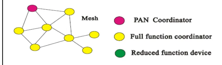
b) Mesh Topology
[image:22.595.144.523.619.730.2]7
In the Mesh topology, there is also one PAN coordinator. In contrast to star
topology, any device can communicate with any other device as long as they are in
range of one another. A Mesh network can be ad-hoc, organizing and
self-healing. Applications such as industrial control and monitoring, wireless sensor
networks assert and inventory tracking wood benefit from such a topology. Mesh
topology also allows multiple hopes to root massages from any device to any other
device in the network and can provide reliability by multipath rooting.
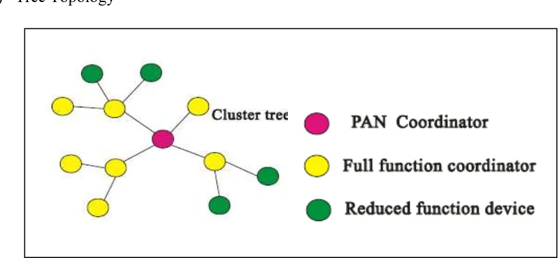
c) Tree Topology
Figure 2.4: Tree Topology
Cluster tree network is special case of Mesh network in which most devices are FFD’s and an RFD may connect to a cluster tree network as a leave node at the end of a branch. Any of the FFD can act as a coordinator and provide
synchronization services to other devices and coordinators. Only one of this
coordinator however is the PAN coordinator. The PAN coordinator forms the first
cluster by establishing itself as the cluster head (CLH) with a cluster identifier (CID)
of zero, choosing an unused PAN identifier, and broadcasting beacon frames to
neighboring devices. A candidate device receiving a beacon frame may request to
join the network at the CLH.
If the PAN coordinator permits the device to join, PAN coordinator will add
this new device as a child device in neighbor list. The newly joined device will add
8
other candidate devices may then join the network at that device. The advantage of
this clustered structure is the increased coverage area at the cost of increased
message latency.
2.1.3 Difference between Bluetooth and ZigBee
ZigBee looks rather like Bluetooth but is simpler, has a lower data rate and
spends most of the time in snoozing. This characteristic means that a node on a
ZigBee network should be able to run for six months to two years on just two AA
batteries. The operational range for ZigBee is 10 to 75 meters compared to 10 meters
for Bluetooth (without a power amplifier). ZigBee sits below Bluetooth in terms of
data rate. The data rate of ZigBee is 250 kbps at 2.4 GHz 40 kbps at 915MHz and 20
kbps at 868 MHz where as that of Bluetooth is 1Mbps.
ZigBee uses a basic master slave configuration suited to static star networks
of many infrequently used devices that talk via small data packets. ZigBee allows up
to 254 nodes. Bluetooth protocol is more complex since Bluetooth is geared towards
handling voice, images and file transfers in ad hoc networks, Bluetooth devices can
support scatter nets of multiple smaller non synchronized networks. Bluetooth only
allows up to 8 slave nodes in a basic master slave Pico net setup. When ZigBee node
is powered down, Bluetooth can wake up and get a packet in around 15 milliseconds
where as a Bluetooth device would take around 3 seconds to wake up and respond
[5].
2.2 Liquid Crystal Display (LCD)
This component is specifically manufactured to be used with
microcontrollers, which means that LCD cannot be activated by standard IC circuits.
LCD is used for displaying different messages on a miniature liquid crystal display.
The model described here is for low price and great capabilities most frequently used
in practice. LCD is based on the HD44780 microcontroller (Hitachi) and can display
messages in two lines with 16 characters each. LCD also can display all the letters of
alphabet, Greek letters, punctuation marks, mathematical symbols. Moreover, LCD