UNIVERSITI TEKNIKAL MALAYSIA MELAKA
DIMENSIONAL ACCURACY OF THE PLATINUM FARO ARM
FOR REVERSE ENGINEERING PRODUCTS USING FUSED
DEPOSITION MODELING
This report submitted in accordance with requirement of the Universiti Teknikal Malaysia Melaka (UTeM) for the Bachelor Degree of Manufacturing Engineering
(Design of Manufacturing) (Hons.)
By
AMIN BIN ABDULLAH HAPIPI B051110343
901119-14-5177
i
ABSTRAK
ii
ABSTRACT
iii
DEDICATION
To my lovely parents, my brother and sister who give me encouragement to success in my studies and not to forget special thanks to all my lecturers and friends that give
iv
ACKNOWLEDGEMENT
Firstly I would like to thank of Almighty Allah for His blessing for his power for me to complete this project successfully. I would like to forward my utmost gratitude to my supervisor, Encik Baharudin bin Abu Bakar for being my supervisor, also give me guideline and inducement to complete my project which is "Dimensional Accuracy Of The Platinum Faro Arm For Reverse Engineering Products Using Fused Deposition Modelling".
I would like to send my appreciation to all technician that help me, especially to technician at Platinum Faro Arm Encik Fairuz bin Ninggal, FDM Machine Encik Hairuddin bin Kanan and also assistant engineer Encik Sahar bin Salehan.
Lastly I would like to thanks to my parents Abdullah Hapipi bin Daimon and Norlidah binti Ayob because always support me and give me advice until I completing my Final Year Project. Also, my sincerely appreciation to all my friend who helping me in completion of this project.
v
TABLE OF CONTENT
Abstrak i
Abstract ii
Dedication iii
Acknowledgement iv
Table of Content v
List of Tables x
List of Figures xi
List of Abbreviation xv
CHAPTER 1: INTRODUCTION 1
1.1 Background 1
1.2 Problem Statement 2
1.3 Objective 2
1.4 Scope of study 3
CHAPTER 2: LITERATURE REVIEW 4
2.1 Rapid Prototyping 4
vi
2.1.4 Disadvantage of Rapid Prototyping 9 2.2 Technique in Rapid Prototyping 10
2.2.1 Stereolithography 10 2.2.1.1 Advantage of SLA 11 2.2.1.2 Disadvantage of SLA 11 2.2.1.3 SLA Machine Specification from 3D System 11 2.2.1.4 SLA Products 12 2.2.2 Selective Laser Sintering 12 2.2.2.1 Advantage of SLS 13 2.2.2.2 Disadvantage of SLS 13 2.2.2.3 SLS Machine Specification from E-Manufacturing 14
vii
2.3.2 Applications Using Reverse Engineering 20 2.3.3 Type of Reverse Engineering 20 2.3.3.1 Contact Method 20 2.3.3.2 Non-Contact Method 22 2.3.4 The Reverse Engineering Technique 23 2.4 Cad Software in Local Industry 23
2.4.1 Solidwork 24
viii
3.8.3 Editing using Geomagic Studio Software 42 3.8.4 Starting the Geomagic Studio 44
3.9 3D Scanning 47
3.9.1 The Results Generating After Scanning Process 48
3.9.2 Polygon Phase 50
CHAPTER 4: RESULT & DISCUSSION 54
4.1 Introduction 54
4.2 Dimensional Accuracy Measured Data 55 4.2.1 Dimensional Accuracy for Machining Part 1 55 4.2.1.1 Result measurement for Machining Part 1 56 4.2.1.2 Comparison between Actual Product and Prototyping of 57
Machining part 1
4.2.2 Dimensional Accuracy for Machining Part 2 61 4.2.2.1 Result measurement for Machining Part 2 62 4.2.2.2 Comparison between Actual Product and Prototyping of 63
Machining part 2
ix
4.2.3.2 Comparison between Actual Product and Prototyping of 70 Bracket
CHAPTER 5: CONCLUSION AND RECOMMENDATION 73
5.1 Conclusion 73
5.2 Recommendation 73
REFERENCE 75
APPENDICES 78
Appendix A 78
x
LIST OF TABLES
2.1 The Historical Development of RP and Related Technologies 6 2.2 SLA Machine Specification 11 2.3 SLS Machine Specification 14 2.4 FDM Machine Specification 16 2.5 LOM Machine Specification 18
3.1 Machine Specification 34 3.2 Specification for Mitutoyo Vernier caliper 36 3.3 Specification of Platinum Faro Arm 37 3.4 Specification for FDM 400mc 39 3.5 Tab Available In the Main Application Window 46
xi
LIST OF FIGURES
2.1 Rapid Prototyping Process 7 2.2 Tessellation of a Typical Surface of CAD Model 8 2.3 The Sthereolithography Process 10 2.4 Sample of SLA Product 12
2.10 Contact Scanning Touch Probe 21 2.11 Figure 2.11: a) MicroScribe MX Articulated Arm b) Faro Arm-Platinum 21
articulated arm form Fero Technologies c) Mitutoyo CMM machine CRA Apex C model
xii
3.1 Project Overview 30
3.2 Methodology Process Flow 31 3.3 Experiment Apparatus 32
3.4 CMM Wenzel LH 54 34
3.5 Mitutoyo Vernier Caliper 36 3.6 Platinum Faro Arm Equipment 38
3.7 FDM 400mc Machine 39
3.8a Actual and drawn product for Machining Part 1 40 3.8b Actual and drawn product for Machining Part 2 40 3.8c Actual and drawn product for Bracket 40 3.9 Basic Studio Workflow 43 3.10 Point Phase - Ordered Points - Single Scan 44
3.11 Window Layout 45
xiii 3.18a Repair Intersection and Relax Polygon of Machining Part 1 53 3.18b Repair Intersection and Relax Polygon of Machining Part 2 53 3.18c Repair Intersection and Relax Polygon of Bracket 53
4.1 The Rapid Prototyping of Machining Part 1, Machining Part 2 54 and Bracket
4.2 Drawing Machining Part 1 55
xiv
4.13 Graph Comparison Dimension Thickness for Machining Part 2 67
4.14 Drawing Bracket 68
xv
LIST OF ABBREVIATION
FDM - Fused Deposition Modeling ABS - Acrylonitrile Butadiene Styrene 3D - Three Dimensional
RP - Rapid Prototyping
R&D - Research and Development NC - Numerical Control
CAD - Computer Aided Design STL - Tesselation
SLC - Stereolithography Contour CLI - Common Layer Interface SLA - Stereolithography
LOM - Laminated Object Manufacturing RE - Reverse Engineering
1
CHAPTER 1
INTRODUCTION
1.1 Background
The growth of engineering field is faster. Many companies have to compete each other to produce new products in the manufacturing industries. New product, technology and system have been introduced to identify the best solution to fulfil their customers demand and satisfaction. Rapid Prototyping and Reverse Engineering are the new technologies that now all the companies have been used for this purpose. These technologies will make the engineering field easier to get better dimensional accuracy, easier to produce, lower cost and analysis for any parts or products.
2
Rapid prototyping is important in the process of design and quite beneficial as far as decrease the project cost and risk in manufacturing. Rapid manufacturing is powerful technology in new revolution application. The process is more faster to develop prototype or working a model for any king of design, feature, concept, functionality and performance.
1.2 Problem Statement
Rapid prototyping is a modern technology that is faster method to produce product than conventional method. However, in Rapid Prototyping also have some disadvantage which is the product that product produced by Fused Deposition Modelling (FDM) are not consistently measured accurately as compared to the actual product measurement.
From this problem, we will carried out that the product dimensions by product drawing and scanned drawing and produced by FDM. The measurement of dimensions under repeated FDM production is not consistently accurate.
1.3 Objective
The objectives of the study are:
a) To study the dimensional accuracy of Reverse Engineering products using Platinum Faro Arm and FDM machine.
3
1.4 Scope of study
4
CHAPTER 2
LITERATURE REVIEW
2.1 Rapid Prototyping
Rapid prototyping are technique that in used to produce a solid model or physical models from three dimensional (3D) Computer Aided Design data. The 3D printing machine allow for engineer or designers to quickly create a real prototypes of their design Chapela et. al (2013). RP represent a method that applied modern
manufacturing technologies to produce parts on layer by layer. These methods are less time used up compared with conventional method. Utilize of RP will increases the dependability of the product and profit of manufacturing. Rapid prototyping are one and only of the names applied to a new group of technologies for converting designs from computer representations instantly into solid objects without human intervention. No single one of the many technologies has yet proven that it can meet all market requirements, so those intending to be involved in this industry should know the fundamental processes, limits, and potentials of the competing machines.
5
models from rapid prototyping technique are used to create of models for tooling machine such as silicone rubber molds and investment casts.
The term "rapid" as it applies to RP technologies is relative. Even the fastest RP fabrication process can take from 3 to 72 hours, depending on the size and complexity of the prototype. Nevertheless, all of these methods are faster than the weeks or even months required to fashion a prototype by traditional hand-crafted carving or machining methods (Singh., 2013).
Rapid prototyping is a global industry that now includes manufacturers of prototype building equipment, contract prototype building services, and companies that perform both manufacture of equipment and offer building services. The importance of this RP industry can be seen from the growing list of participants in equipment manufacture and building services in the United States, Canada, South and Central America, Europe, and Asia. RP model-making equipment is being sold for in-house use by manufacturers, government and corporate R&D laboratories, and the engineering departments of vocational schools and universities.
2.1.1 History of Rapid Prototyping
6
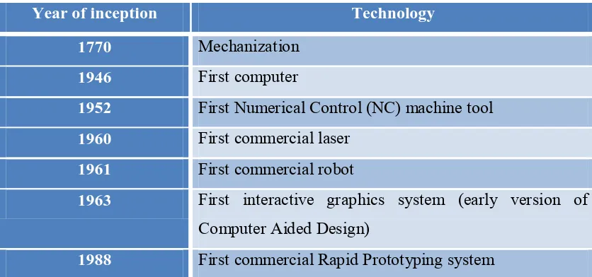
Next stage and the newest trend of prototyping for example RP product layer by layer material deposition, it began on early 1980s with the large growth in Computer Aided Design and Manufacturing (CAD/CAM) technologies when almost straightforward solid model with knitted information of edged and surface could define as a product. The historical developing of RP and related technologies is representing in table 2.1. ( Chua, Leong. K, K.F.,2000)
Table 2.1: The Historical Development of RP and Related Technologies
Year of inception Technology
1770 Mechanization
1946 First computer
1952 First Numerical Control (NC) machine tool
1960 First commercial laser
1961 First commercial robot
1963 First interactive graphics system (early version of
Computer Aided Design)
1988 First commercial Rapid Prototyping system
The earlier usage of additive manufacturing was in rapid prototyping (RP) on the late 1980s and early on 1990s. Prototypes admit manufacturers a chance to examine an object's design more closely and even test it before producing a finished product. RP allowed producer produce those prototypes much quicker than before, often within daytimes or sometimes hours of conceiving the design. In designers, RP create models using computer-aided design (CAD) software, and then machines follow that software model to find out how to build the object. The process of building that object by "printing process" it has cross-sections layer by layer became known as 3-D printing.
7
with no support of an unused material, which would serve as support for more complicated structures. The most frequently used material in FDM prototyping is acrylonitrile butadiene styrene (ABS); however, other materials are also utilized, including polycarbonate, polyphenylsulphone, and elastomers.
2.1.2 Basic Principle of Rapid Prototyping Processes
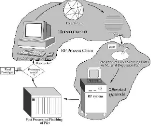
The Rapid Prototyping process consist to the addictive production procedure that not equivalent with shaping or reductive processes. As commercialise RP processes, the part is fabricated by deposition of layers contoured in an x-y plane two dimension. For the third dimension z outcome are from single layers being stacked up on top of each other, but not as a continuously z-coordinate. So that, the prototypes are very accurate on the x-y plane but have stair stepping consequence in z-direction. Rapid Prototyping also can be classified into two basic process steps namely generation of mathematical layer data and generation of physical layer model (Pandey et. al.,2003a)
8
The figure 2.1 that process starts with 3D modeling of the product and then STL file is exported by tessellating the geometric 3D model. In tessellation various surfaces of a CAD model are piecewise approximated by a series of triangles (Figure 2.2) and co-ordinate of vertices of triangles and their surface normal are listed. These STL files are checked for defects like flip triangles, missing facets, overlapping facets, dangling faces or edges etc. and are repaired if found faulty. Defect free STL files are used as an input to various slicing software. At this stage choice of part deposition orientation is the most important factor as part building time, surface quality, amount of support structures, cost etc. are influenced. Once part deposition orientation is decided and slice thickness is selected, tessellated model is sliced and the generated data in standard data formats like SLC (stereolithography contour) or CLI (common layer interface) is stored.
Figure 2.2: Tessellation of a Typical Surface of CAD Model