UNIVERSITI TEKNIKAL MALAYSIA MELAKA
THERMAL BEHAVIOR OF NATURAL FIBER MAT HYBRID
COMPOSITE FOR TOOLING MATERIALS
This report submitted in accordance with requirement of the Universiti Teknikal Malaysia Melaka (UTeM) for the Bachelor Degree of Manufacturing Engineering
(Engineering Materials) (Hons.)
by
NOR FARIHA BINTI SOHOD B 051010218
890109-04-5112
UNIVERSITI TEKNIKAL MALAYSIA MELAKA
BORANG PENGESAHAN STATUS LAPORAN PROJEK SARJANA MUDA
TAJUK: Thermal Behavior of Natural Fiber Mat Hybrid Composite for Tooling Materials
SESI PENGAJIAN: 2012/13 Semester 2
Saya NOR FARIHA BINTI SOHOD
mengaku membenarkan Laporan PSM ini disimpan di Perpustakaan Universiti Teknikal Malaysia Melaka (UTeM) dengan syarat-syarat kegunaan seperti berikut:
1. Laporan PSM adalah hak milik Universiti Teknikal Malaysia Melaka dan penulis. 2. Perpustakaan Universiti Teknikal Malaysia Melaka dibenarkan membuat salinan
untuk tujuan pengajian sahaja dengan izin penulis.
3. Perpustakaan dibenarkan membuat salinan laporan PSM ini sebagai bahan pertukaran antara institusi pengajian tinggi.
4. **Sila tandakan (√)
SULIT
TERHAD
TIDAK TERHAD
(Mengandungi maklumat yang berdarjah keselamatan atau kepentingan Malaysiasebagaimana yang termaktub dalam AKTA RAHSIA RASMI 1972)
(Mengandungi maklumat TERHAD yang telah ditentukan oleh organisasi/badan di mana penyelidikan dijalankan)
Alamat Tetap:
NO. 127, Kampung Baru Ayer Keroh,
75450 Melaka.
Tarikh: _________________________
Disahkan oleh:
Cop Rasmi:
Tarikh: _______________________
DECLARATION
I hereby, declared this report entitled “ Thermal Behavior of Natural Fiber Mat Hybrid Composite for Tooling Materials” is the results of my own research except as cited in references.
Signature :
Author‟s Name : NOR FARIHA BINTI SOHOD
APPROVAL
This report is submitted to the Faculty of Manufacturing Engineering of UTeM as a partial fulfillment of the requirements for the degree of Bachelor of Manufacturing Engineering (Engineering Materials) (Hons.). The members of the supervisory committee are as follow:
……… (MISS CHANG SIANG YEE)
i
ABSTRAK
ii
ABSTRACT
iii
DEDICATION
To my beloved parents, supervisor, co-supervisor, siblings, lecturers and friends.
iv
ACKNOWLEDGEMENT
v
TABLE OF CONTENT
Abstrak i
Abstract ii
Dedication iii
Acknowledgement iv
Table of Content v
List of Tables viii
List of Figures ix
List Abbreviations, Symbols and Nomenclatures xii
CHAPTER 1: INTRODUCTION 1
1.1 Background 1
1.2 Problem Statement 3
1.3 Objectives 3
1.4 Scope 4
CHAPTER 2: LITERATURE REVIEW 5
2.1 Tooling 5
2.1.1 Metallic Tooling 6
2.1.2 Composite Tooling 7
2.1.2.1 Polymer Matrix 8
2.1.2.2 Fiber Reinforcement 11
2.2 Hybrid Composites 13
2.2.1 Types of Fiber 14
2.2.1.1 Synthetic Fiber – Glass Fiber 16 2.2.1.2 Natural Fiber – Jute Fiber 18
vi
2.3 Hand Lay-up and Vacuum Bagging 23
2.4 Effect of Stacking on Hybrid Composites 25
2.4.1 Physical Properties 25
2.4.2 Mechanical Properties 27
2.4.3 Thermal Properties 29
2.5 Effect of Orientation on Hybrid Composites 31
2.5.1 Dimensional Stability 31
2.5.2 Thermal Properties 34
CHAPTER 3: METHODOLOGY 36
3.3 Characterization of Raw Materials 40
3.3.1 Electronic Densimeter 40
3.3.2 Scanning Electron Microscope (SEM) 41 3.4 Fabrication of Laminated Hybrid Composites 41 3.4.1 Preparation of Stacked Hybrid Laminate Composite 42 3.4.2 Fabrication of hybrid laminate composite 43
3.5 Sample Preparation of Composites 45
3.6 Characterization of Composites 46
3.6.1 Physical Properties 46
3.6.1.1 Density 46
3.6.1.2 Water Absorption 46
3.7 Testing 47
3.7.1 Thermal Cycling 47
3.7.2 Flexural Test 48
3.8 Microscopic Observation 50
vii
CHAPTER 4: RESULTS & DISCUSSION 53
4.1 Characterization of Raw Materials 53
4.1.1 Density 54
4.1.2 Scanning Electron Microscopy (SEM) 55
4.2 Characterization of Composites 55
4.2.1 Density 56
4.2.2 Water Absorption 57
4.3 Testing of Composites 60
4.3.1 Thermal Cycling 61
4.3.2 Flexural Testing 66
CHAPTER 5: CONCLUSIONS & FUTURE WORK 74
5.1 Conclusions 74
5.2 Future Work 76
REFERENCES 77
APPENDICES 84
Gantt chart PSM 1 84
viii
LIST OF TABLES
2.1 2.2 2.3 2.4 2.5
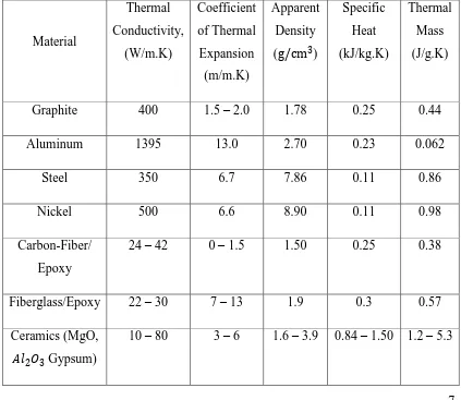
Typical Properties of Tooling Materials Some typical properties of thermosets Properties of fiber materials
Chemical composition of jute fibers Physical properties of some natural fibers
7 11 17 19 20
3.1 3.2
3.3
Product specification of Epoxy Resin (DM15 (F3)
Fiber mat orientation and staking sequence of jute/glass fiber reinforced epoxy
Detailed description on fabrication of hybrid laminate composite
37 42
43
ix
LIST OF FIGURES
2.1 Arrangement of polymer chain: (a) cross-linked, (b) linear, (c) branched.
Chemical structure of typical epoxy. Typical reinforcement types.
Classification of natural and synthetic fibers.
(a)Basic unit of SiO2, (b) combination of two units, (c) the
structure of glasses is a three dimensional network based on silica but usually modified by the presence of other elements.
Chemical structure of cellulose. Laminated composite.
Lamina and laminate lay-up. Hand Lay-up.
Vacuum bagging with outlet vacuum line and resin feed line. Vacuum bagging set up schematic.
SEM image of tensile fractured surface of laminate under flexural load.
TGA results for treated/untreated hybrid composites of sisal/glass.
DSC results for treated/untreated composites sisal/glass at 2cm fiber length.
Thermally induced loads.
x
3.4 Dessicator. 39
3.5 Electronic densimeter. 40
3.6
Dimensions of water absorption test specimen.
Dimensions of flexural and dimensional stability test specimen. Oven.
Universal Testing Machine. Digital Imaging Microscopy. Flow chart methodology
SEM micrograph of bleached jute fiber under magnification of 300x.
Density of jute/glass fiber reinforced composite at different orientation and stacking sequence.
Water absorption of jute/glass fiber composite at different orientation and stacking sequence for duration of three weeks. Jute/glass fiber reinforced laminate composite experienced swelling after water absorption test.
Change in thickness of jute/glass fiber reinforced epoxy laminate composite at different composition.
Thickness loss of (a) 7 plies and (b) 9 plies of jute/glass fiber reinforced epoxy laminate composite at different orientation and stacking sequence.
Different weight loss versus number of heating cycles of (a) 7 plies (b) 9 plies of jute/glass fiber reinforced epoxy laminate composite at different orientation and stacking sequence on 7 plies.
Discoloration occurred after heating for 15 cycles on (a)
jute/glass fiber reinforced epoxy laminate composite (S7 – 2) and (b) glass fiber reinforced epoxy laminate composite.
xi 4.10
4.11
4.12
4.13
aged of S9 – 2 lamiante composite after 15 thermal cycles. Comparison of (a) flexural strength, (b) flexural modulus and (c) stiffness of laminate composite at 0 thermal cycle.
Fracture mode of jute /glass fiber reinforced epoxy laminate composite at 0 thermal cycle (a) S7 – 1 (GGGGGGG), (b) S7
– 3 (GGG‟GG‟GG), (c) S7 –2 (GJ‟GJ‟GJ‟G) and (d) S7 – 4
(GJ‟GJGJ‟G).
Comparison of (a) flexural strength, (b) flexural modulus and (c) stiffness of jute/glass fiber reinforced epoxy laminate composite at different orientation and stacking sequence, prior to and post thermal cycling.
Cross section of (a) 0 cycle on S9 – 1, (b) 15 cycles on S9 – 1, (c) 0 cycle on S9 – 4 and (d) 15 cycles on S9 – 4 of glass fiber reinforced epoxy laminate composite at different orientation and stacking sequence after flexural test.
68
69
71
72
xii
LIST OF ABBREVIATIONS, SYMBOLS AND
NOMENCLATURE
ASTM - American Standard Test method CTE - Coefficient of thermal expansion DSC - Differential Scanning Calorimetry FRP - Fiber Reinforced Plastics
NASA - National Aeronautics and Space Administration PLA - Poly (lactic acid)
PMC - Polymer Matrix Composites PVC - Polyvinyl chloride
SE - Secondary electron
SEM - Scanning Electron Microscope SiO2 - Silica
SME - Society of Manufacturing Engineers TGA - Thermogravimetric Analysis
UTM - Universal Testing Machine UV - Ultra-violet light
Mi - immersion weight Mo - original weight Mw - weight gain
Pmax - maximum load at failure (N) σmax - maximum stress
ºC - degrees Celsius 0
F - degrees Fahrenheit W/mK - thermal conductivity
m/m/ ºC - coefficient of thermal expansion g/cm3 - density
xiii J/g.K - thermal mass
in - inch
mm - milimeter
µ - micron
GPa - gigapascal MPa - megapascal MPam1/2 - fracture toughness
1 This chapter introduces the background, problem statement, objectives as well as the scope of the study.
1.1 Background
Nowadays, the aerospace industry manufactures increasingly larger components which require the use of larger tools. High performance, cost effective materials are used to produce the tools to ensure the quality of the end-product and sustainability of the tooling. Traditionally, metals have been used as tooling materials for composite processing. However, the weight of metal tooling has become an issue particularly for manufacturing of large aerospace components. Consequently, lightweight materials would be preferred to accomplish this task. Introduction of hybrid composite materials as tooling materials has weight advantage over the metals and produces stronger components. Hybrid composite which is made of two or more different kinds of fiber in single matrix, provides better combination of properties than composite containing single fiber (Callister., 2006).
At present, synthetic fiber reinforced composite is widely used by manufacturers to produce tooling. The drawbacks of the synthetic composites tooling are associated with its high cost and limitation of recyclability. Satyanarayana et al. (2009) as cited in Jawaid et al. (2011) highlighted that glass fiber costs approximately 1200 –
2 1800US$/tones which is almost twice the price of the natural fibers. Besides, according to National Composite Network (2006), the issue of recycling composite poses great impact on the environment. This is due to the lack of clear and well-developed recycling routes (logistics, infrastructure and recycling technologies). Additionally, disposal of carbon or glass fiber by incineration is detrimental to our mother earth (Nishino et al., 2003).
To circumvent the problem, green hybrid composite tooling is an alternative by partial replacement of the synthetic fiber with the presence of natural fiber in the composite tooling. Incorporation of natural fibers in the composite presents a number of advantages such as low tool wear, low density, cheaper cost, abundance availability and the most importantly its biodegradability (Akil et al., 2011).
Natural fiber reinforced composites have found applications in automobile and furniture industries as the composites possess comparable mechanical properties to that of glass fiber reinforced composites (Sabah et al., 2012). Thus, the venture of green hybrid composite into composite tooling is highly promising. Among the natural fibers available in the market, jute, flax and coir show the prominent properties in engineering applications.
3 1.2 Problem Statement
During the manufacturing of aerospace components, tooling used is usually made of carbon fiber or glass fiber reinforced epoxy composite which is difficult to be recycled or disposed. As a green hybrid composite tooling, the incorporation of natural fiber and synthetic fiber in these tooling materials could lead to new venture in tooling industries. Tooling material is subjected to repeated thermal cycling during in service and is likely to induce distortion on the tooling due to the difference in thermal mass and coefficient of thermal expansion between the natural fiber and synthetic fibers. However, no studies have been undertaken to determine thermal history of the natural fiber in composite. Besides, hybrid configuration is also important to achieve optimum result by varying the fiber orientation and the stacking sequence of natural fiber/glass fiber laminae in order to overcome the dimensional instability, low thermal degradation and moisture absorption of hybrid composites associated with natural fibers.
1.3 Objectives
1. To fabricate natural fiber/ glass fiber reinforced epoxy hybrid composite by varying fiber orientation and stacking sequence of natural and glass fiber laminae through hand lay up and vacuum bagging techniques.
2. To characterize the physical, and mechanical behavior of natural fiber/ glass fiber reinforced epoxy hybrid composite in order to establish structure – property relationship.
4 1.4 Scope
In this research, jute fiber mat and E-glass fiber mat were used as reinforcement in the epoxy laminate composite. The laminate composite was fabricated through hand lay up and vacuum bagging techniques by varying the stacking sequence of fiber laminae and fiber orientation (0 /90 or 45 /-45 ). Two composite systems
5 A literature review on previous research work in various areas which is relevant to this research is presented in this chapter.
2.1 Tooling
In manufacturing applications, tooling required to fabricate most composite parts can be subdivided into several major category including ply layup tools, skin or mould forms, curing aids, handling tools, drilling and trimming tools, assembly tools, mould and mandrels (National Aeronautics and Space Administration, NASA, 1990). However, mould which used forming composite part is known as tools. In aerospace industry, mold is widely used during hand lay-up process. According to NASA (1990) cited major factors must be considered in design and fabrication of tooling for structural and mechanical components are:
i. Dimensional tolerance control and configuration stability – low coefficient of thermal expansion (CTE) is required.
ii. Location of part in structural reliable assembly to give the lowest possible cost.
iii. Contour and size of the part. iv. Control the fiber orientation.
6 v. Other factors: cost, tool service life, heat up rate, total energy
requirements, production rates and related facility costs.
From Lucas and Danford (2009) also had highlighted tooling is critically important where mold tool must be low-cost, rigid and durable and offer a CTE that matches of the composites part. (Stewart, 2010) also had mentioned the tooling must be cost effective, UV resistant, damage to tolerance and able to resist environmental degradation in maintaining the dimensional and stability of tooling. Therefore, long lead times and material availability is also growing concerns with alloy-based tools.
2.1.1 Metallic Tooling
7
2.1.2 Composite Tooling
Due to the excessive weight of metal tooling resulted many manufacturers have turned to composite tooling. Cadden and Sadesky (1998) stated composite mould tooling has several basic advantages. For instance, composite tooling is a low cost because the composite prepreg materials can be laid on plaster model and then cured, the CTE of tooling materials is compatible, and graphite mould tools provide uniform temperature distribution which allows the composite part heated up evenly and prevent internal residual stress. In addition, if damage occurs new tool can be fabricated rapidly and economically from original master model. Table 2.1 provides some properties for most commonly used tooling materials.