ISSN 1991-8178
The New Generation of Building Control Concept to Suppress the Horizontal
Vibration during the Earthquake
1
M.A.Salim,
2A.Noordin,
3J.Karjanto,
4M.Z.M.Rody
1
Faculty of Mechanical Engineering, Universiti Teknikal Malaysia Melaka Locked Bag 1752,
Pejabat Pos Durian Tunggal 76109 Durian Tunggal, Melaka, Malaysia.
2,3,4
Faculty of Electrical Engineering, Universiti Teknikal Malaysia Melaka Locked Bag 1752,
Pejabat Pos Durian Tunggal 76109 Durian Tunggal, Melaka, Malaysia.
Abstrack: Most of the current researches are to suppress the vibration during the earthquake for the building and always focused on either full state feedback strategies or velocity strategies. An accurate measurement is a necessary such as displacement and the velocities of the building are difficult to achieve directly, particularly during the seismic activity. In this study, it was proposed that the new generation of building control concept to suppress the horizontal vibration during the earthquake by using an active mass damper (AMD) system. The Lagrange’s, D’Alembert’s and Newton Second Law techniques are used to derive the two dimensional mathematical model of second order differential equation of AMD system. Four diagrams of stability analysis were used to identify the stability of the system before making an experimental and simulation analysis. Regarding the stability analysis, AMD system is good enough to give a positive feedback during the application of the force of vibration. Then, by using MATLAB-SIMULINK, the model was analyzed again in an experimental and simulation analysis. In this analysis, both of the result is reasonably closed where the correlation is more than 95 percent, and this would give positive responses such as time response and amplitude in order to suppress a vibration during the earthquake disaster.
Key words: Lagrange’s, D’Alembert’s, Newton Second Law, Active Mass Damper
INTRODUCTION
Nowadays, due to the advance technologies in engineering and improvement in material quality, the structures such as high building and expanded bridge span become more relevant. This would make the structures to be subjected to series of the structural vibration when considering about the location exposed to the earthquake or strong windfall. Vibration can be pleasant and useful as in massaging and therapeutic application but at the same time it can be unpleasant and harmful because it can lead to catastrophic failures of components and materials. Unwanted vibration can cause a lot of trouble such as damage to structures and reduction of equipment performance and increase machinery noise level. Even electronic components used in automobile or planes, machine and also structure may fail because of the vibration.
Structural control is a different field of study. It is a one area of important research that look promising in attaining about reducing the vibration if loadings happen such as an earthquake or strong winds. In addition, the structural control can be divided into passive, active, semi active and hybrid control depending to the consumption energy which are offering more option to mitigate the loss and damage caused by the natural hazards.
Many researchers had agreed that the new generation of control research in control engineering application should be focused on developing systems that are more implementable (Salim et al., 2009; Fujita, 1994; Higashino and Aizawa, 1993; Hurai, 1993). For example, it would need to trend towards building taller and at the same time it also take the higher flexible structure have resulted in design which more vulnerable to severe dynamics loadings. In addition, according to this new generation of control system, the vibration happen in the building can also be absorbed 100% and because of that this study focus is to design a new building control concept where it has better damping, spring and dynamic motor. Besides that, it is also focused on the forces that buildings must withstand which are live and dead loads Salim et al., (2009). Dead loads refer to permanent and do not move load while live loads refer to loads that move.
New building control concept:
The new generation of building control concept in this study is called new design of active mass damper (AMD). An active mass damper is also known as a tuned mass damper (TMD) or harmonic absorber is a device mounted in structures to prevent discomfort, damage or outright structural failure caused by vibration Ismura, and Izuno, (1993). It is frequently used in power transmission and automotive industry.
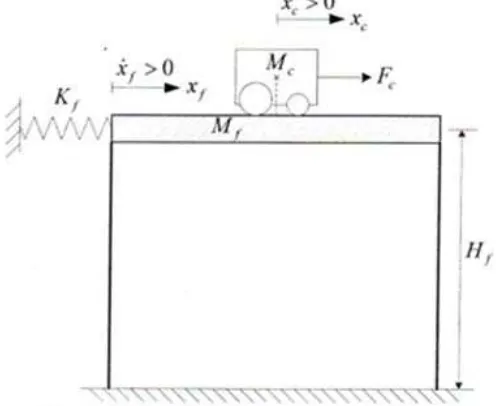
The working principle of AMD is by using a two-degree of freedom vibration structures. When then actuator is stopped, the active mass combines with the passive mass and both are regarded as dynamic absorber (Villarreal, 2005; Kobori, 1991). AMD schematic diagram is shown in Figure 1 below.
Fig. 1: Schematic diagram of active mass damper
The Lagrange’s technique is used to derive the mathematical model of two degree of freedom of AMD. By using this technique, the potential and kinetic energies of the system can be derived. The total potential energy, in a system is the amount of the energy of the system. This energy can make a vertical displacement from normality (gravitational potential energy) or by a spring related sort of displacement (elastic potential energy). According to this situation, there have no gravitational potential energy with the both of AMD cart and the structure is assumed to stay at a constant elevation. The top floor of the AMD is modeled as a linear spring mass system. The total energy of AMD is only due to the elastic potential energy Salim, (2009).
The total potential energy of the AMD can be represent by,
(1) The kinetic can be measured because the amount of the energy in a system is due to the motion. The total kinetic energy is called as. This total energy is the summation of translational and rotational kinetic energies to the linear cart of the motor. Thus, this total energy can be formulated as,
(2) The translational kinetic energy for the cart of the motor as a function of the center of the gravity can be expressed by,
The rotational kinetic energy for the DC motor is,
(4)
Then, the structure floor translational kinetic energy can be expressed by,
(5)
By replacing the equation 3, 4 and 5 into equation 2, the new total kinetic energy can be represented by,
(6)
The two Lagrange’s equation, and has the following of the formulations as,
(7)
And
(8)
From equation 7 and 8, can be represented as,
L=TT-VT (9)
For the system, the general force can be defined as,
(10)
From equation 7, the Lagrange’s technique is used to calculate the equation and express to the following equation.
(11)
Use Lagrange’s technique again to express the equation 8. The new equation is,
(12)
(13)
And
(14)
Equation 13 and 14 can be representing the equation of motion (EOM) for AMD linear system. If the value of and neglected, the new equation are,
(15)
And
(16)
Transfer Function of Active Mass Damper:
The basic equation of force that applied to the AMD is,
(17)
The inertial rotation of the motor’s armature can be neglected. The dynamic model of this motor will be more accurate. Then, the inertial force of the cart will be applied to the Newton’s second law of the motion with the D’Alembert’s principle equation. The equation can be expressed by,
(18)
For the motor pinion, the armature inertial force into the motor rotation and it can act to the armature inertial torque. The equation can be expressed by,
(19) Then, using the Newton’s second law, the equation of motion of the motor shaft can be expressed by,
(20) The mechanical configuration of the cart’s rack opinion system can be defined at the following relationship,
Substitute the equation 20 and 21 into equation 19. The new equation of armature inertial force is,
(22) And
(23)
Then, substitute equation 17 and 22 into equation 23. By rearranging, the new equation can be expressed by,
(24) From equation 24, it is expressed by second order differential equation in the cart position. Using the Laplace Transform technique and rearranging for open loop transfer function, the new equation of AMD can be expressed by,
(25)
Stability analysis:
The stability analysis is one important analysis to make sure that the AMD system is stable in order to suppress the vibration happen during the earthquake. Four analyses has been make to analysis the system and there are,
1. Step response diagram analysis 2. Bode diagram analysis
3. Root locus diagram analysis 4. Nyquist diagram analysis
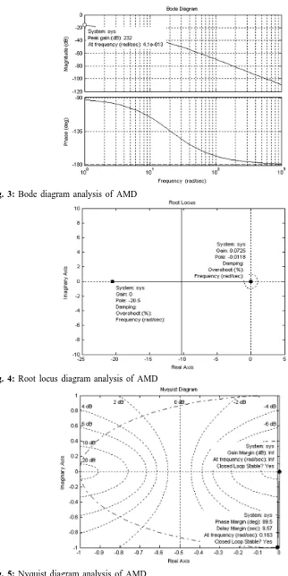
Fig. 3: Bode diagram analysis of AMD
Fig. 4: Root locus diagram analysis of AMD
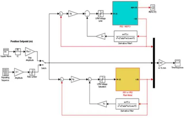
Fig. 6: AMD model in earthquake vibration (Experiment versus Simulation)
From Figure 2, the rise time of AMD system is approximately 23.1 seconds, the peak amplitude is 5.43e+003, the overshoot is 0% and time take to stabilize the system is approximately 60 seconds. According to this result, the system is stable to suppress the vibration during the earthquake and the time taken is 60 seconds.
In bode diagram analysis the value of the peak gain is approximately 232 dB. Then the frequency of peak gain is 4.1e-013 radian/seconds. Based on this data, the frequency of this system is very small and because of that the system can be operated on the frequency which occurs during the earthquake.
Then, from root locus diagram analysis the system is stabilized because the straight line at point 1 is not touching to the point 2. According this data, the system can be suppress and give a positive response when the building is moving by horizontal direction.
In Nyquist diagram analysis, the gain margin point 1 is infinity but closed loop system is in stable. Then, the phase margin value of the system is approximately to 89.5 degree and delay margin is 9.57 degree. The frequency response due to this system is only 0.163 radian/seconds. Based on this data, the system is stable and is can give an immediately response if earthquake happen under the building.
According to all analyses, the AMD system has a good potential to suppress the vibration regarding to the building. The further analysis in MATLAB-SIMULINK has been conducted to analysis the movement of AMD during the earthquake.
Result of experiment and simulation:
Based on equation 24 and 25, the model of AMD system can be expressed by,
In order to AMD model in Figure 6, it has shown the block diagram to analyze the result in experiment and simulation during the earthquake vibration. The following figures are shown the response given by the model to suppress the vibration during the earthquake.
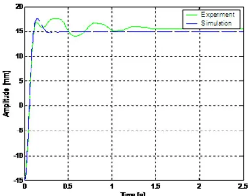
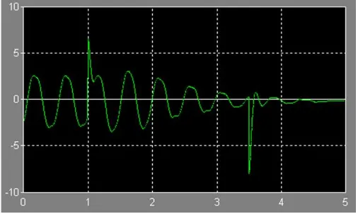
In Figure 7, it has shown the result of AMD response an experiment and simulation during the earthquake. Based on these both result, the AMD system was suppressed the vibration less than 0.5 seconds in a time response and on 17 mm for the amplitude. The final value of the system is 15 mm. For both of the results, it is reasonable closed and it means the AMD system can be used to suppress the vibration in a building during the earthquake vibration.
Fig. 7: Experiment versus Simulation result for AMD system
(a) AMD response at frequency 25 Hz
(c) AMD response at frequency 75 Hz
(d) AMD response at frequency 100 Hz
(e) AMD response at frequency 150 Hz
Fig. 8: AMD response at frequency 25 Hz, 50 Hz, 75 Hz, 100 Hz and 150 Hz
Conclusion:
verification, it can be concluded that the AMD system can be used to suppress the vibration in a building during the earthquake disaster.
NOMENCLATURE
Symbol Description Value Unit
Structure floor height 0.53 M
Flexible structure total mass 1.60 kg
Structure top floor mass 0.68 kg
Rack mass 0.70 kg
Top floor of natural frequency 2.5 Hz
Top floor linear stiffness constant 500 N/m
Cart mass 0.39 kg
Cart weight mass 0.13 kg
Cart travel 0.19 m
Rack pitch 1.664e-003 m/tooth
Cart motor nominal input voltage 6.0 V
Cart motor input voltage maximum frequency 50 Hz
Cart motor armature resistance 2.6
Cart motor armature inductance 0.18 mH
Cart motor torque constant 0.00767 N.m/A
Cart motor efficiency 100 %
Cart back electromotive force (EMF) constant 0.00767 V.s/rad
Symbol Description Value Unit
Structure floor height 0.53 M
Equivalent viscous damping coefficient, as seen at the motor pinion 3.0 N.s/m
Cart planetary gearbox gear ratio 3.71
Cart planetary gearbox efficiency 100 %
Cart motor pinion radius 6.35e-003 m
Cart motor pinion number of teeth 24
Cart position pinion radius 1.48e-002 m
Cart position pinion number of teeth 56
Cart encoder resolution 2.275e-005 m/count
Cart potentiometer sensitivity 0.0931 m/V
Floor accelerometer sensitivity 9.81 m/s2/V
ACKNOWLEDGEMENT:
The author would like to thank for Malaysian to Faculty of Mechanical Engineering, Universiti Teknikal Malaysia Melaka for the technical and financial supports.
REFERENCES
Fujita, T., 1994. Application of Hybrid Mass Damper with Convertible Active and Passive Modes Using Hydraulic Actuator to High Rise Building, Proceeding of the 1994 America Control Conference, IEEE., 1067 –1072.
Higashino, M., S. Aizawa, 1993. The Application of Active Mass Damper System in Actual Building, Proceeding of the Institute Workshop on Structural Control, University of Southern California,
Hurai, J., A. Hisanori, E. Tsuji, 1993. Study on Tuned Mass Damper for Control Tower of Kansai International Airport, Proceeding of the Institute Workshop on Structural Control, University of Southern California,.
Kobori, T., N. Koshika, K.Yamada, Y. Ikelda, 1991. Seismic Response Controlled Structure with Active Mass Driver System. Proceeding of the 1991 IEEE Verification Earthquake and Structural Engineering Dynamic, Japan, 65-86.
Ismura, H., K. Izuno, 1993. Development of the Self Oscillating TMD and Shaking Table Test, Proceeding of the Institute Workshop on Structural Control, University of Southern California,
Salim, M.A., M.K.M. Nor, M.F. Hassan, 2009. Analysis of Absoption the Level of Vibration Energy in a Building Structure Using PID Controller, Second International Conference and Workshops on Basics and Basic Applied Sciences & Regional Annual Fundamental Science, Malaysia, ICORAFFS 09, Page 99 – 105, ISBN 978 – 983 – 9805 – 74 – 1.