iii
HOME EQUIPMENT CONTROL BY USING HOME PHONE SIGNAL
NOR ASIAH BT MAT YUNUS
This report is submitted in partial fulfillment of the requirements for the award of Bachelor of Electronic Engineering (Computer Engineering) With Honours
Faculty of Electronic and Computer Engineering Universiti Teknikal Malaysia Melaka
iii
UNIVERSTI TEKNIKAL MALAYSIA MELAKA
FAKULTI KEJURUTERAAN ELEKTRONIK DAN KEJURUTERAAN KOMPUTER
BORANG PENGESAHAN STATUS LAPORAN
PROJEK SARJANA MUDA II
Tajuk Projek : HOME EQUIPMENT CONTROL BY USING HOME PHONE SIGNAL
Sesi
Pengajian : 2009/2010
Saya NOR ASIAH BT MAT YUNUS
mengaku membenarkan Laporan Projek Sarjana Muda ini disimpan di Perpustakaan dengan syarat-syarat kegunaan seperti berikut:
1. Laporan adalah hakmilik Universiti Teknikal Malaysia Melaka.
2. Perpustakaan dibenarkan membuat salinan untuk tujuan pengajian sahaja.
3. Perpustakaan dibenarkan membuat salinan laporan ini sebagai bahan pertukaran antara institusi
pengajian tinggi.
4. Sila tandakan ( √ ) :
SULIT*
(Mengandungi maklumat yang berdarjah keselamatan atau kepentingan Malaysia seperti yang termaktub di dalam AKTA RAHSIA RASMI 1972)
TERHAD* (Mengandungi maklumat terhad yang telah ditentukan oleh organisasi/badan di mana penyelidikan dijalankan)
TIDAK TERHAD
Disahkan oleh:
__________________________ ___________________________________ (TANDATANGAN PENULIS) (COP DAN TANDATANGA PENYELIA)
Alamat Tetap : N0 5, JLN MURNI 2, TAMAN MAS MERAH, 75350 BT BERENDAM, MELAKA.
iii
“I hereby declare that this thesis entitled, Home Equipment Control By Using Home Phone Signal is a result of my own research idea concept for works that have been
cited clearly in the references.”
iv
“I hereby declare that I have read this report an in my opinion this report is sufficient in terms of the scope and quality for the award of Bachelor of Electronic Engineering
(Computer Engineering) With Honours”
v
vi
ACKNOWLEDGEMENT
vii
ABSTRACT
viii
ABSTRAK
ix
CONTENT
CHAPTER CONTENT PAGE
PROJECT TITLE i
REPORT STATUS VERIFICATION FORM ii
STUDENT’S DECLARATION iii
SUPERVISOR’S DECLARATION iv
DEDICATION v
ACKNOWLEDGEMENT vi
ABSTRACT vii
ABSTRAK viii
CONTENTS ix
LIST OF TABLES xiii
LIST OF FIGURES xiv
LIST OF SYMBOLS AND ABBREVIATIONS xvi
LIST OF APPENDICES xvii
I INTRODUCTION
1.1 Introduction of Project 1
1.1.1 Overall System 2
1.2 Objective 4
1.3 Problem Statement 5
1.4 Scope 5
1.6 Methodology 8
x
II LITERATURE VIEW
2.1 Introduction 10
2.2 Dual Tone Multiple Frequency( DTMF) 11
2.2.1 Introduction of DTMF 11
2.2.2 Specification 12
2.2.3 Component Description 13
2.2.4 Implementation 16
2.3 Microprocessor 17
2.3.1 Component Description 17
2.3.2 Implementation 18
2.4 LED Display 19
2.4.1 Component Description 19
2.4.2 Implementation 19
2.5 Power Supply 20
2.5.1 Component Description 20
2.5.2 Implementation 21
2.6 Relay 22
2.6.1 Component Description 22
2.6.2 Implementation 22
2.7 ULN2003 22
2.7.1 Component Description 22
2.7.2 Implementation 23
2.8 ATS 138 23
2.8.1 Component Description 23
2.8.2 Implementation 23
2.9 H11AA4 24
2.9.1 Component Description 24
2.9.2 Implementation 24
2.10 MPLAB 25
2.10.1 Component Description 25
xi 2.11 Comparing other Project with This Project 27
III CIRCUIT DESIGN
3.1 Etching Process 30
3.2 Prepare The PCB for Use and Drill The PCB 33 3.3 The Subsystem and The Function 34
3.4 Schematic for The Project 36
3.5 User Interface Specification 39
IV SOFTWARE DESIGN
4.1 Flow Chart of Software Design 42
4.2 Programming 47
V EXPERIMENT AND RESULT
5.1 Experiment for DTMF Circuit 49
5.2 Result of Experiment for DTMF 50
5.3 Experiment for Microcontroller 51
VI 5.4 Expected Result 53
5.5 Actual Result 55
5.5.1 Password Setting 55
5.5.2 Telephone Interface 55
5.5.3 Device Status Checking 55 5.5.4 Device Switching Unit ( Relay Output) 55 5.6 Software Result 56
VII DISCUSSION
xii
VII CONCLUSION AND RECOMMENDATION
7.1 Conclusion 61
7.2 Recommendation 62
REFERENCES 64
APPENDIX A 65
xiii
LIST OF TABLE
NO TITLE PAGE
2.2.1 The frequencies associated with various keys on the keypad 12 2.2.3(a) Functional Decode ( 0 = Logic low, 1 = Logic high) 14
2.2.3(b) CM8880 pin Table 14
2.5.2 Voltage Requirement of Each Component 21
3.5 Description of The Main Menu 40
5.2 Result 50
xiv
LIST OF FIGURE
NO TITLE PAGE
1.1(a) Collaboration Diagram of Home Phone Signal (HomePS) 2
1.1(b) Overview this project 4
1.6.1 Flow chart of The Method 9
2.2.3 CM8880-PI Single End Input Connection 16
2.3.1 Pin Diagram of PIC 168F73 Microprocessor 18
2.3.2 Basic Microcontroller Implementation Diagram 19
2.4.1 LED Diagram 19
2.4.2 Block Diagram of LED 20
2.5.1 L7805CV 21
2.6 Relay 22
2.9(a) Schematic of H11AA4 24
2.9(b) Standard Thru Hole 24
2.10.2(a) Design Phase 26
2.10.2(b) MPLAB Programming 26
3.1(a) Tape cover of the PCB is Removed 31
3.1(b) PCB Board is put Under the UV light 31
3.1(c) PCB in developing process 31
3.1(d) PCB Circuit before come out from MEGA 32
3.1(e) PCB Circuit after come out from MEGA 33
xv
3.3 Subsystem 35
3.4(a) Schematic of DTMF Communication Circuit 36
3.4(b) Schematic of Central Control Unit 36
3.4( c) The PCB of circuit HomePS 36
3.4(d) The Layout of circuit HomePS 37
3.4(e) Central control Unit 39
3.4(g) Owner Appliance Unit Circuit 39
3.5 User Interface Flow Chart 41
4.1(a) General Step of Programming 43
4.1(b) Detail on Step of Programming 44
5.1 Circuit Experiment 49
5.2 DTMF Result 50
5.3(a) PIC Burner 51
5.3(b) Test port for PIC controller 53
5.5 The complete connection of the HomePS 55
5.6(a) Debugging Program 56
xvi
LIST OF SYMBOLS AND ABBREVIATIONS
ADC - Analog to Digital Converter DC - Direct Current
CCU - Central Control Unit OAU - Owner Appliance Unit DC - DTMF Circuit
HomePS - Home Phone Signal
EEPROM - Electrical Erasable Programmable Read Only Memory MOSFET - Metal Oxide Semiconductor Field Effect Transistor RAM - Random Access Memory
PIC - Programmable Interrupted Controller DC - Direct Current
PCB - Printed Circuit Board CG I/O - Input/ Output
xvii
LIST OF APPENDICES
NO TITLE PAGE
A CM8880 65
1 CHAPTER 1
INTRODUCTION
1.1 Introduction of Project.
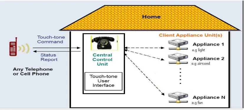
2 function of this system by using PIC microcontroller. The system collaboration diagram in Figure 1.1(a) and Figure 1.1(b) Overview of this project illustrates how each subsystem in Home Equipment Control Using Home Phone Signal (HomePS) interacts with one another.
Figure 1.1(a): Collaboration Diagram of Home Phone Signal (HomePS)
1.1.1 Overall System
The HomePS consists of several functional components as outlined in Figure 1.1(a). My design includes one central control unit circuit, DTMF circuit and four client appliance units.
i. Central Control Unit(CCU)
[image:19.612.115.529.175.362.2]3
ii. DTMF Unit (DC)
The function of this circuit is to convert the line telephone to the binary data using IC CM8880. The DTMF communication unit is responsible for calling the designated client appliance unit, which in turn is responsible for actually operating the designated appliances.
iii. Client Appliance Unit (CAU)
4 Figure 1.1(b): Overview of this project
1.2 Objectives
The project is a aimed to achieve this objectives:
i) To build the main hardware system that can convert the line phone by using DTMF
signal to binary signal.
ii) To design Home Appliance Control System over line phone with any telephone device.
iii) To understand the architecture and programming of the PIC. iv) To learn troubleshooting and analyzing.
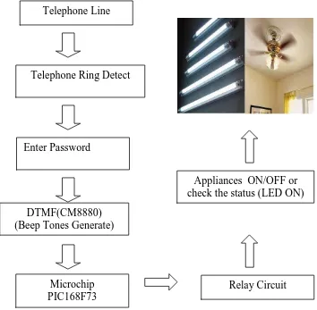
Telephone Line
Telephone Ring Detect
Enter Password
DTMF(CM8880) (Beep Tones Generate)
Relay Circuit Appliances ON/OFF or check the status (LED ON)
[image:21.612.177.531.84.431.2]5 1.3 Problem Statement
i) If someone forgets or not sure whether the home appliances one turn ON or OFF, they can monitor the appliances using the phone.
ii) This project is to design and develop a system which will help users to makes protective because this device can trigger the alarm and informs the owner via automatic phone ringing.
iii) This system is suitable for all homes. It is because the system has a simple function and do not use a lot of circuits and less cost. It also saves electricity because this device will enable the users to control the appliances by using the telephone from anywhere.
1.4 Scope
The scopes that are to be concentrating in this project are:
i) Home appliances control using DTMF signal to be operated using the local phone
and mobile phone as the remote phone.
ii) This system manipulates Dual Tone Multi Frequency (DTMF) and PIC technology.
iii) Four relays will be used as switching devices. iv) The tools that will be used is :
MPLAB IDLE.
6 1.5 Report Structure
This report contains of seven chapters that explain detail about this project. The first chapter is introduction of the project. This chapter contain of project introduction, project objectives, project scope, problem statement and research methodology.
The second chapter is literature discuss the theory of the components and implementation that is used in the project. This chapter also discuss the comparing with others project. So, it is very important to understand the concepts involve and how this system works.
The third and fourth chapter is Project Methodology. This chapter will figure out a few tests that have been conducted. This is to make sure the components and other devices involves are in good condition function. The testing procedures, devices and method used to generate the expected results will include in this chapter. This chapter also contains of the process design program that was describe in the flowchart. A lot of term and variable needs to determine for declaration in program. The term of input and output must be identifying in order to build the program.
7 1.6 Methodology
Firstly, this project starts by searching for literature reviews from books and journals as a readability sources. Then the suitable circuits were identified. The circuits are The Central Control Unit (CCU), DTMF communication (DC) and Owner Appliance Unit (OAU). The CCU will be connected to the household phone line and will receive and process a touch-tone command sent by an owner’s phone home. While for DC circuit is to convert the line telephone to the binary data using IC CM8880. The next
circuit is OAU which is control the home devices when press some key in the phone. Secondly, the next activities are circuit design and programming. Circuit will be
design by using PROTEL, PROTEUS and MULTISIM software. Beside this, frame work for programming need to draw to help the programmer clearly to start their work.
The next stage would be simulation for the circuit. Labs experiments are the way to verify the overall designed are operation. Beside that, MPLAB software will be used as compiler in programming. MPLAB Integrated Development Environment (IDE) is a free, integrated toolset for the development of embedded applications employing Microchip's PIC® and dsPIC® microcontrollers. MPLAB IDE runs as a 32-bit application on MS Windows®, is easy to use and includes a host of free software components for fast application development and super-charged debugging. MPLAB IDE also serves as a single, unified graphical user interface for additional Microchip and third party software and hardware development tools. Moving between tools is a snap, and upgrading from the free software simulator to hardware debug and programming tools is done in a flash because MPLAB IDE has the same user interface for all tools.1
The big part of the project is programming. I need to learn how to implement C programming as a compiler in MPLAB. A part from that, the syntax also needs to identify to make the synchronizations between software and hardware.
1http://www.microchip.com/stellent/idcplg?IdcService=SS_GET_PAGE&nodeId=1406&dDocName=en0