! " # $ !
! " " # # #
(
% &' ( ' )
* + ,
' - ...
$ / 0 - $ $
)) (
6 6 +
!
" $ !, +
-...,, " ' $"% $0 %0 $ 77$ !
!
"
#
$
%
! & !
! !
! ! " ! ! !
! # ! !
! '
! & ! ! ()
! ! ! & ! ! !
! ! & ! !
# %
* +
, -. / -$ # /
. 0 ! %
1 ! ! !
.
. &
& &
!
0 ! !
# #
8 3 6 0 " , 4 4 >6
8 3 6 ( 0 0 4 -50/ >6
8 3 8 0 $ 4 >:
8 3 8 ( 0 * 4 -5*/ >?
8 3 : 0 " $ >?
8 3 : ( 50* 4 * >3
8 ; 4 >;
8 ; ( 0 >>
8 ; ) * (26
8 ; 6 $ (26
(23
? ((6
3 ((8
%
8 )) ! ! 9 0 * >>
8 )6 0 + ! >>
8 )8 + ! 5 = 0 (22
(2)
8 ): * + ! (26
8 )? 4 50* (28
8 )3 " (28
8 ); A ()A (2:
8 )> % (2?
: 2 $ (2;
: ( $ (2>
: ) $ " ((2
%
8 2 % * * 3)
8 ( 4 36
1
A permanent magnet direct current (dc) motor is a very common component within many
dynamic systems. This case study describes the physics of a standard dc motor. From this
general understanding, differential equations are developed to describe the motor’s
dynamic behavior. State space equations and Laplace transforms are then developed for
further analysis and for application to a light tracking system. Typical data for a specific
motor are included within a Matlab/Simulink program to illustrate the basic time domain
behavior of the system. System modeling methods for analysis, design and regulation
purposes have conventionally employed lumped linear and non&linear methods to provide
the dynamic and steady state information required. This approach although simple and
appealing assumes that the system components have no spatial dimensions, each element,
for example, comprising stiffness, inertia and frictional dissipation characteristics, all of
which exist at some undefined point in space. Adequate though this may be when the
components employed are largely concentrated, physically, as system dispersion and
slenderness ratios increase, the dynamics arising from spatial distribution assume
increasing relevance. Recognition of this and attempted accommodation, via the
promotion of approximation and empiricism, has often resulted in a lack of confidence in
the computed predictions obtained. Finite element (fe) methods, for example, are often
incorporated in efforts aimed at replicating the effects of spatial dispersion. However, this
approach generates large matrix models, computational errors, and erroneous modes of
2
modeling was investigated for mechanical, power transmission system modeling, were
also researched and accurate, compact, computationally efficient realizations, for
controller design and real&time diagnostics, were derived. At this time single loading
effects and the dynamics arising from flexible beams, shafts and rotor&bearing assemblies
were addressed. Whirling speed applications studies continued in parallel with this work
using frequency response and numerical minimization methods. In this contribution
previous work will be advanced with a novel combined torsion and tension loading,
machine tool modeling method. The technique involved will be to describe significantly
distributed elements of the machine, such as the lead screw, using distributed parameter
procedures. This approach to the mathematical construction process enables greater
reality, accuracy and integrity to be achieved. Essentially, the system dynamics arising
from the combined, distributed lumped description enable all of the incident, traveling
and reflected waveform effects to be replicated in the final realization. Effectively, the
response signatures generated by the model will be shown to correspond closely with
those from the actual system. In particular, the effects of spatial dispersion and combined,
lead screw, torsion and tension loading provide a broadband realization, capable of
generating the low and high frequency behavior of the system’s, x&axis dynamics. This is
enhanced by the incorporation of lumped nonlinear effects. Details of these
characteristics were obtained, in this study, from manufacturer’s data and from measured,
experimental results. Following, the detailed derivation for the x&axis traverse, motor
drive and the multivariable lead screw model, for combined torsion and tension loading
will be presented. Thereafter, an overall, interactive representation, for the complete
distributed–lumped system configuration, will be derived. Finally, the simulated response
transients for the system, following voltage step changes on the lead screw, motor drive,
will then be computed.
Certain high&speed document handling machines manufactured exhibit the undesirable
3
the system. The objective of this project was to study and analyze a simple test that had
all the relevant attributes of the more complicated machines. The dynamics and control of
a load driven by a DC motor was to be investigated in the context of high&speed high
precision motion control. High performance was desired without risking close&loop
stability. One particular addition of interest is a Simulink graphical model which
automatically performs the appropriate block diagram arithmetic and generates a state
space model for use in a standard Matlab simulation. This model is used here to relate the
output angular velocity of the motor to the input applied voltage. It is also used as a
subsystem in a Simulink model of the complete the simple mechanical design.
! " #$ # % # &
! " #
1. To demonstrate the use of electrical blocks, in combination with Simulink
blocks, in the simulation of an electromechanical system with a control
system. The electrical part of the DC motor drive, including the DC
source, and the DC motor, is built using blocks from the Elements,
Machines, and Electronics libraries in the Matlab Software. The DC
Machine block models both electrical and mechanical dynamics. The load
torque&speed characteristic and the control system are built using Simulink
blocks.
2. Describe various methods of controlling the speed and direction of a DC
motor.
3. Learn the operation and modeling of DC motor systems.
4. Learn the driver circuitry for DC motors.
4
! #
Analyze the output voltage of DC motor that produce for the simple mechanical design
that have power screw. Be able to using the Matlab software to simulate the design and
test to see that the requirements and specification are met.
! ! % &
This project is to study on ‘Dc Motor Control System’. The project scope is to ‘Study the
Control Element in Single Axis Positioning with Consist of Motor, Gearing, Coupling,
and Power Screw’. The software that recommended in this research is Matlab 6.5.1. The
main of this research is to explore and design the mechanical element. From the
mechanical equations, transfer to the control system equations. Then, find the
specification of the element at calculate the value of the dc motor output voltage.
5
' (
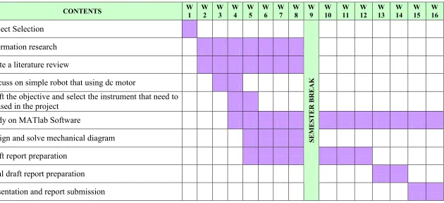
Table 1 Gantt Chart PSM 1.
) ) )
Write a literature review
Discuss on simple robot that using dc motor
Draft the objective and select the instrument that need to be used in the project
Study on MATlab Software
Design and solve mechanical diagram
Draft report preparation
Final draft report preparation
Presentation and report submission
0
1
6
Table 2 Gantt Chart PSM 2.
) ) )! )* )+ )' ), )- ). ) / ) ) ) ! ) * ) + ) '
Find the specifications
Find the transfer function
Simulation using MAtlab software
Analysis the result
Make a discussion
Gathering all information and sources
Draft report preparation
Final draft report preparation
Presentation and report submission
0
1
7
3 4 )
/
An electric motor converts electrical energy into kinetic energy. The reverse task, that of
converting kinetic energy into electrical energy is accomplished by a generator or
dynamo. In many cases the two devices differ only in their application and minor
construction details, and some applications use a single device to fill both roles. For
example, traction motors used on locomotives often perform both tasks if the locomotive
is equipped with dynamic brakes. Most electric motors work by electromagnetism, but
motors based on other electromechanical phenomena, such as electrostatic forces and the
piezoelectric effect, also exist. The fundamental principle upon which electromagnetic
motors are based is that there is a mechanical force on any current&carrying wire
contained within a magnetic field. The force is described by the Lorentz force law and is
perpendicular to both the wire and the magnetic field. Most magnetic motors are rotary,
but linear motors also exist. In a rotary motor, the rotating part (usually on the inside) is
called the rotor, and the stationary part is called the stator. The rotor rotates because the
wires and magnetic field are arranged so that a torque is developed about the rotor's axis.
The motor contains electromagnets that are wound on a frame. Though this frame is often
called the armature, that term is often erroneously applied. Correctly, the armature is that
part of the motor across which the input voltage is supplied. Depending upon the design