THE PERFORMANCE ANALYSIS OF A UAV BASED MOBILE MAPPING SYSTEM
PLATFORM
M.L. Tsai 1, *, K.W. Chiang 2, C.F. Lo 3, C.H. Chu4
1
Dept. of Geomatics, National Cheng Kung University, Taiwan – [email protected] 2 Dept. of Geomatics, National Cheng Kung University, Taiwan – [email protected]
3 GeoSat Informatics Technology Corporation, Taiwan –
Dept. of Geomatics, National Cheng Kung University, Taiwan – [email protected]
Commission I, ICWG I/5
KEY WORDS: Direct georeferencing; INS; GPS; UAV
ABSTRACT:
To facilitate applications such as environment detection or disaster monitoring, the development of rapid low cost systems for collecting near real-time spatial information is very critical. Rapid spatial information collection has become an emerging trend for remote sensing and mapping applications. This study develops a Direct Georeferencing (DG) based fixed-wing Unmanned Aerial Vehicle (UAV) photogrammetric platform where an Inertial Navigation System (INS)/Global Positioning System (GPS) integrated Positioning and Orientation System (POS) system is implemented to provide the DG capability of the platform. The performance verification indicates that the proposed platform can capture aerial images successfully. A flight test is performed to verify the positioning accuracy in DG mode without using Ground Control Points (GCP). The preliminary results illustrate that horizontal DG positioning accuracies in the x and y axes are around 5 m with 300 m flight height. The positioning accuracy in the z axis is less than 10 m. Such accuracy is good for near real-time disaster relief. The DG ready function of proposed platform guarantees mapping and positioning capability even in GCP free environments, which is very important for rapid urgent response for disaster relief. Generally speaking, the data processing time for the DG module, including POS solution generalization, interpolation, Exterior Orientation Parameters (EOP) generation, and feature point measurements, is less than one hour.
* Corresponding author: M.L.TSAI – [email protected]
INTRODUCTION
With the number of natural disasters increasing due to climate change, the development of a rapidly deployable and low cost system for collecting near real-time spatial information has become very critical. Therefore, rapid spatial information acquisition capability has become an emerging trend for remote sensing and mapping applications. Airborne remote sensing, more specifically aerial photogrammetry, in its classical form of film-based optical sensors (analogue) has been widely used for high accuracy mapping applications at all scales and rapid spatial information collection for decades. Recently, film-based optical sensors (analogue) have been replaced by digital imaging sensors.
Generally speaking, conventional photogrammetric methods rely on huge numbers of Ground Control Points (GCP). Although photogrammetry has adopted digital technology, GCPs are generally considered the only source of reliable georeferencing information (Gibson et al, 1992). Recently, Direct Georeferencing (DG) technology has become possible by integrating Global Positioning System (GPS) and Inertial Navigation System (INS), making Exterior Orientation Parameters (EOP) available with sufficient accuracy at any instant of time (Gibson et al, 1992). The integration of INS and GPS improves the georeferencing of photogrammetric data and frees it from operational restrictions. Together with digital data
recording and data processing, it allows multi-sensor mapping systems.
Numerous studies have been conducted on the application of Unmanned Aerial Vehicle (UAV) for photogrammetry applications. A detailed review of UAV photogrammetric applications can be found in (Eisenbeiss, 2004; Eisenbeiss, 2008). Although most schemes apply low cost INS/GPS integrated systems for flight control, a DG based UAV photogrammetric platform equipped with an INS/GPS integrated Positioning and Orientation System (POS) that can provide EOP of the camera in a GCP free environment has not been proposed until recently.
TECHNICAL CONFIGURATIONS OF PROPOSED PLATFORM
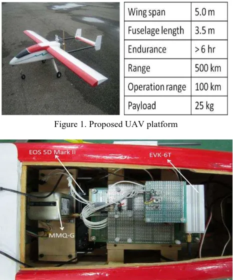
The proposed UAV platform and its specifications are illustrated in Figure 1. As shown in the figure, the proposed UAV is designed for medium range applications. The wing span is 5 m and the payload is 25 kg. The maximum operational range is 100 km and the real-time video transmission range is 100 km with extended range communication links. The flexible flight altitude and six hours endurance make the platform suitable for small area and large scale photogrammetric missions.
Figure 2 shows the DG module designed in this study for facilitating GCP free photogrammetry applications and INS/GPS integrated POS aided bundle adjustment photogrammetry. The EVK-6T GPS receiver from U-blox is used in the DG module. This model is chosen because of its L1 carrier phase measurements for Differential GPS (DGPS) processing, which provides sufficient positioning accuracy. In addition, it supplies Pulse Per Second (PPS) output, which is used to synchronize the time mark used to trigger the camera in the DG module. The IMU used for the DG module is MMQ-G from BEI SDID. This model is chosen due to its compact size and weight. The MMQ-G IMU integrates Micro Electro Mechanical Systems (MEMS) quartz rate sensors (100 deg/hr in run bias) and vibrating quartz accelerometers. To supply the power required for the individual sensors with various power requirements from the battery, a power switch module was designed. An RS232 port is used to transmit the measurements collected by the MMQ-G IMU to the data storage module. Since the camera, a Canon EOS 5D Mark II, has its own power supply, it is not considered in the power supply design. The data storage module used to record the measurements collected by MMQ-G, EVK-6T, and the synchronized time mark used to trigger the camera is Antilog from Martelec. Due to the limitations of the power supply, a PC or notebook based data storage module was ruled out in this study.
Figure 1. Proposed UAV platform
Figure 2. Configuration of DG module
Figure 3 illustrate the general concept of the airborne DG. With this implementation, the coordinates of a mapping feature can be obtained directly through measured image coordinates. This procedure works based on the a priori knowledge of various systematic parameters, as shown in the reference (Fraser, 1997).
Figure 3. Concept of airborne DG
DATA PROCESSING STRETEGY
For the determination of the lever arm and boresight angle parameters, the EOP must be solved using close-range bundle adjustment. However, some errors are introduced during the image measurements due to manufacturing imperfections of cameras. Thus, camera calibration must be performed. The objective of camera calibration is to analyze the Interior Orientation Parameters (IOP), such as lens distortion, focal length, and principle point. These systematic errors can be diminished during the image point measurements. For system calibration and DG measurements, a camera control field and a ground control field were established.
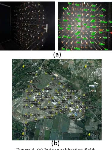
Camera indoor calibration field
Figure 4(a) shows the indoor calibration field applied in this study to calibrate the IOP of Canon EOS 5D Mark II. Because a digital camera is rather than a traditional camera, which can use the flame frame to rectify systematic error and image coordinate measurement, a bundle method with self-calibration is proposed for determining the IOP of the camera (Tao and Li, 2007). The obtained IOP are applied to enhance the accuracy of EOP estimation and the DG task. Figure 4(b) shows the distribution of GCP which are set up every 400 m in the test field. The GCPs are accurately surveyed using the Real Time Kinematic (RTK) GPS surveying technique and processed with network adjustment software. The STandard Deviation (STD) of the GCPs is around 3 mm, and thus they are applied to calibrate the lever arm and boresight angle.
Ground control field
In this research, a two-step approach is implemented to conduct the lever arm and boresight angle calibrations. The image acquisition for the calibration process was performed by flying the UAV photogrammetric platform over the ground control field at a flight height of 300 m. The measurements of the image points were processed. Australis software was then used to calculate the EOP of the images through bundle adjustment. After performing the interpolation of INS/GPS positioning and orientation parameters at the image exposure time, the differences of the position and the orientation between the EOP acquired by a conventional photogrammetry procedure and interpolated INS/GPS positioning and orientation parameters were derived for further processing.
(a)
(b)
Figure 4. (a) Indoor calibration field; (b) Distribution of GCPs in test field
In theory, the lever arm and boresight rotation matrices derived from each image are the same; however, this is not exactly true in practice. Reasonable values from the calibration can be determined using appropriate weights or the average distribution. After obtaining the calibration parameters, the DG task can be performed without using any GCP. Figure 5 illustrates the DG based photogrammetric process proposed in this study (Chiang et al, 2012).
Figure 5. Proposed DG-ready photogrammetric procedure
Integrated POS data processing
Post-mission processing, when compared to real-time filtering, has the advantage of having the data of the whole mission to estimate the trajectory (Shin and El-Sheimy, 2005). This is not possible when using filtering because only part of the data is available at each trajectory point, except the last. When filtering is used in the first step, an optimal smoothing method, such as Rauch-Tung-Striebel (RTS) backward smoother, can be applied (Chiang et al., 2004). It uses the filtered results and their covariances as a first approximation. This approximation is
improved by using additional data that was not used in the filtering process. Depending on the type of data used, the improvement obtained by optimal smoothing can be considerable (Gelb, 1974).
For georeferencing process which puts POS stamps on images and measurement process that obtains three-dimensional coordinates of all important features and stores them in Geographic Information System (GIS) database, only post-mission processing can be implemented based on the complexity of those processes (El-Sheimy, 2002). Therefore, most of commercially available DG systems operate in real time only for data acquisition and conduct most of the data processing and analysis in post-mission mode.
RESULTS AND DISCUSSIONS
To validate the performance of the proposed platform, a field test was conducted in the fall of 2011. The area of the test zone was 3 km × 3 km, which is covered by the red square shown in Figure 6(a). The blue region indicates the fly zone approved for this test. The flight altitude for aerial photography was set to 300 m above ground. Owing to the limit of the payload and the impact of side wind affecting the attitude of the UAV, the endlap and sidelap were increased to 80% and 40%, respectively, to insure that the coverage of the stereo pair overlapped completely during the test flight. Although more images have to be processed, complete coverage of the stereo pair is guaranteed. Figures 6(b) and (c) illustrate the flight path and estimated coordinates for the camera exposure center along the trajectory, respectively.
(a)
(b)
(c)
Figure 6. (a) Test area; (b) Trajectories of test flight; (c) Camera exposure center
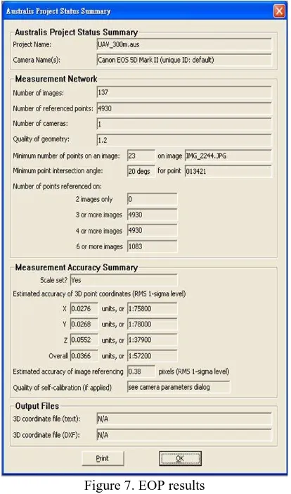
Table 1 shows the preliminary IOP results. The error of the camera calibration is acceptable at this stage, and may be improved in future work. Figure 7 shows the EOP results. The estimated accuracy of image referencing is 0.38 pixels. The influence of the EOP is around 0.04 m in terms of the three-dimensional positioning accuracy.
Table 1. IOP of EOS 5D Mark II
Figure 7. EOP results
A two-step approach was implemented to acquire the lever arm and boresight angle of each camera. Table 2 and 3 shows the lever arm and boresight angle results, respectively.
Table 2. Lever arm calibration result
Table 3. Boresight angle calibration result
Verification of DG Capability of Proposed UAV Photogrammetric Platform
The DG module, developed in Visual Studio 2008 C++, is applied to calculate the coordinates of the check points. As shown in Figure 8, the coordinates of the control points, IOP, and EOP derived from INS/GPS integrated POS solutions are imported into the software. The users can perform image point measurements on different images for a given feature. The results of the space intersection are obtained from various images that have common points of interest.
Figure 8. DG software
The reference coordinates of twenty check points are obtained through a precise control survey with GPS RTK technology and network adjustment software with 1-2 cm three-dimensional positioning accuracy. Therefore, their positioning accuracies are sufficient to be applied as the reference information required for performance verification.
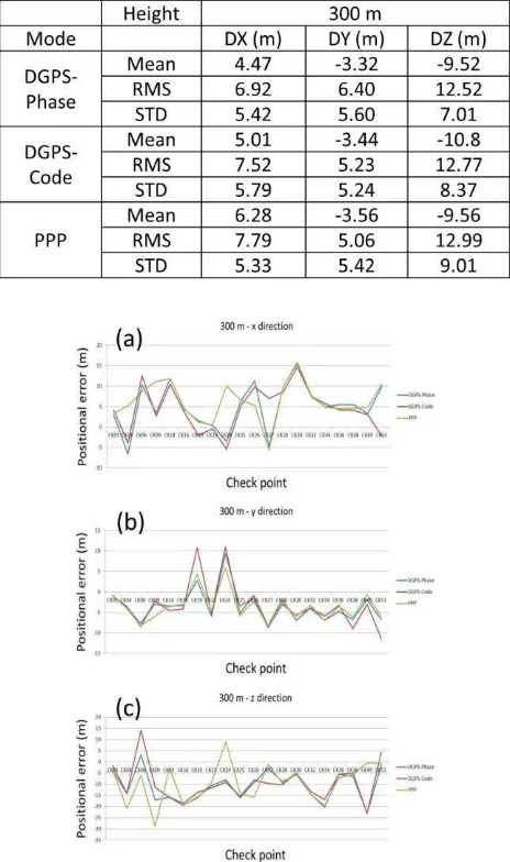
Three types of POS solutions, including those obtained using DGPS and PPP processing strategies, are applied to generate the coordinates of twenty check points through the DG software developed in this study. The solutions are compared with pre-survey known coordinates to validate the performance of the proposed platform. In order to consider and remove the error of pointing by human, we record the image coordinate of each check points. Therefore, the source of the position errors is only from the POS systems. Table 4 shows a performance summary of the proposed UAV borne DG photogrammetric platform operated in GCP free mode using different processing strategies. Figure 9 is 300 m positional errors.
Generally speaking, the positioning accuracies of the proposed UAV borne DG photogrammetric platform operated in GCP free mode using DGPS processing strategies are quite similar. When the flight height is 300 m, the horizontal absolute DG positioning accuracy is around 5-10 m and the vertical absolute DG positioning accuracy is around 10-15 m. Because 300 m flight height is lower, there is no significant difference between the positioning accuracies obtained using PPP and DGPS mode. This finding is consistent with the land test results, where the kinematic positioning accuracy of trajectories generated with DGPS strategies was less than 1 m.
Therefore, for rapid disaster assessment applications where ground reference information is not available, the proposed UAV borne DG photogrammetric platform operated in a GCP free environment using PPP and DGPS mode with L1 carrier phase measurements can provide geo-referenced spatial information with sufficient positioning accuracy.
Table 4. Performance summary of proposed UAV platform in GCP free mode
Figure 9. Error in (a) X; (b) Y; (c) X direction with 300 m
CONCLUSION
This study developed a UAV based DG photogrammetric platform where an INS/GPS integrated POS system is implemented to provide the DG capability of the platform. Tests verified that the proposed platform can capture aerial images. The preliminary results illustrate that horizontal DG positioning accuracies in the x and y axes are around 5 m at a flight height of 300 m. The positioning accuracy in the z axis is less than 10 m. Such accuracy is good for near real-time disaster relief. Such accuracy is good for near real time disaster relief. The DG ready function of proposed platform guarantees mapping and positioning capability even in GCP free environments, which is very important for rapid urgent response for disaster relief. Generally speaking, the data processing time for the DG module, including POS solution generalization, interpolation, EOP generation, and feature point measurements, is less than one hour.
In addition, future studies will be conducted to implement a static ground calibration procedure to improve the DG positioning accuracy of the proposed platform. A one-step approach will be developed to guarantee accurate lever arm and boresight angle calibrations and a cluster based tightly coupled
integrated scheme will be investigated to guarantee the stability of POS solutions for practical GCP-free applications.
ACKNOWLEDGMENTS
The authors acknowledge the financial support by the National Science Council of Taiwan (NSC 100-2119-M-006-023). Dr. Cheng-Feng Lo and his colleagues from GeoSat Informatics Technology Co are acknowledged for assisting the development of the UAV platform as well as their assistance in conducting the test flight.
REFERENCES
Gibson, J.R., Schwarz, K.P., Wei, M., and Cannon, M.E., 1992, GPS-INS data integration for remote sensing, Position Location and Navigation Symposium, IEEE PLANS '92., IEEE , pp. 480. Eisenbeiss, H., 2004, A mini unmanned aerial vehicle (UAV): system overview and image acquisition, International Archives Photogrammetry Remote Sensing and Spatial Information Sciences, vol. XXXVI, on CD-ROM.
Eisenbeiss, H., 2008, The autonomous mini helicopter: a powerful platform for mobile mapping, International Archives Photogrammetry Remote Sensing and Spatial Information Sciences, vol. XXXVII, pp. 977-983.
Fraser, C.S., Digital camera self-calibration, ISPRS Journal of Photogrammetry and Remote Sensing, vol. 52, no. 4, pp. 149-159.
Tao, C.V., and Li, J., 2007, Advance in mobile mapping technology, International Society for Photogrammetry and Remote Sensing (ISPRS) Book Series, Taylor and Francis, London, UK.
Chiang, K.W., Tsai, M.L., and Chu, C.H., 2012, The development of an UAV borne direct georeferenced photogrammetric platform for ground control point free applications, Sensors, vol. 12, no. 7, 1424-8220.
Shin, E.H., and El-Sheimy, N., 2005, Navigation Filter Design for Pipeline Pigging, Journal of Navigation, Cambridge University Press, Vol. 58, pp. 283-295.
Chiang, K.W., Noureldin, A., and El-Sheimy, N., 2004, A New Weight Updating Method for INS/GPS Integration Architectures Based on Neural Networks, Measurement Science and Technology, Vol.15, No.10, pp. 2053-2061.
Gelb, A., 1974, Applied Optimal Estimation, The Analytic Science Corporation.
El-Sheimy, N., 2002, Introduction to Inertial Navigation, Geomatics Department, University of Calgary, ENGO 699.71 lecture notes.