e t h e r n e t
n e t w o r k s
F o u r t h E d i t i o n
Books by Gilbert Held, published by Wiley
Quality of Service in a CiscoNetworking Environment 0 470 84425 6 (April 2002)
Bulletproofing TCP/IP-Based Windows NT/2000 Networks 0 471 49507 7 (April 2001)
Understanding Data Communications: From Fundamentals to Networking, Third Edition
0 471 62745 3 (October 2000)
High Speed Digital Transmission Networking: Covering T/E-Carrier Multiplexing, SONET and SDH, Second Edition
0 471 98358 6 (April 1999)
Data Communications Networking Devices: Operation, Utilization and LAN and WAN Internetworking, Fourth Edition
0 471 97515 X (November 1998)
Dictionary of Communications Technology: Terms, Definitions and Abbreviations, Third Edition
0 471 97517 6 (May 1998)
Internetworking LANs and WANs: Concepts, Techniques and Methods, Second Edition
0 471 97514 1 (May 1998)
e t h e r n e t
n e t w o r k s
F o u r t h E d i t i o n
♦
Design
♦
Implementation
♦
Operation
♦
Management
GILBERT HELD
Copyright2003 John Wiley & Sons Ltd, The Atrium, Southern Gate, Chichester,
West Sussex PO19 8SQ, England Telephone (+44) 1243 779777
Email (for orders and customer service enquiries): [email protected] Visit our Home Page on www.wileyeurope.com or www.wiley.com
All Rights Reserved. No part of this publication may be reproduced, stored in a retrieval system or transmitted in any form or by any means, electronic, mechanical, photocopying, recording, scanning or otherwise, except under the terms of the Copyright, Designs and Patents Act 1988 or under the terms of a licence issued by the Copyright Licensing Agency Ltd, 90 Tottenham Court Road, London W1T 4LP, UK, without the permission in writing of the Publisher. Requests to the Publisher should be addressed to the Permissions Department, John Wiley & Sons Ltd, The Atrium, Southern Gate, Chichester, West Sussex PO19 8SQ, England, or emailed to [email protected], or faxed to (+44) 1243 770571.
This publication is designed to provide accurate and authoritative information in regard to the subject matter covered. It is sold on the understanding that the Publisher is not engaged in rendering professional services. If professional advice or other expert assistance is required, the services of a competent professional should be sought.
Other Wiley Editorial Offices
John Wiley & Sons Inc., 111 River Street, Hoboken, NJ 07030, USA Jossey-Bass, 989 Market Street, San Francisco, CA 94103-1741, USA Wiley-VCH Verlag GmbH, Boschstr. 12, D-69469 Weinheim, Germany
John Wiley & Sons Australia Ltd, 33 Park Road, Milton, Queensland 4064, Australia John Wiley & Sons (Asia) Pte Ltd, 2 Clementi Loop #02-01, Jin Xing Distripark, Singapore 129809
John Wiley & Sons Canada Ltd, 22 Worcester Road, Etobicoke, Ontario, Canada M9W 1L1
British Library Cataloguing in Publication Data
A catalogue record for this book is available from the British Library ISBN 0-470-84476-0
Typeset in 10.5/13pt Melior by Laserwords Private Limited, Chennai, India Printed and bound in Great Britain by Biddles Ltd, Guildford and King’s Lynn
c o n t e n t s
Preface
xv
Acknowledgments
xix
Chapter 1
Introduction to Networking Concepts
1
1.1 WIDEAREANETWORKS 2
COMPUTER-COMMUNICATIONSEVOLUTION 2 REMOTEBATCHTRANSMISSION 2
IBM 3270 INFORMATIONDISPLAYSYSTEM 3 NETWORKCONSTRUCTION 5
NETWORKCHARACTERISTICS 8 1.2 LOCALAREANETWORKS 8
COMPARISON TOWANS 9
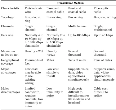
TECHNOLOGICALCHARACTERISTICS 14 TRANSMISSIONMEDIUM 22
ACCESSMETHOD 29 1.3 WHYETHERNET 33
Chapter 2
Networking Standards
37
2.1 STANDARDSORGANIZATIONS 37
NATIONALSTANDARDSORGANIZATIONS 38 INTERNATIONALSTANDARDSORGANIZATIONS 39 2.2 THEISO REFERENCEMODEL 40
LAYEREDARCHITECTURE 41 OSI LAYERS 42
DATAFLOW 46
viii
c o n t e n t s
2.3 IEEE 802 STANDARDS 48 802 COMMITTEES 48 DATALINKSUBDIVISION 51 2.4 INTERNETSTANDARDS 55
RFC EVOLUTION 56 TYPES ANDSUBMISSION 56 OBTAININGRFCS 57 2.5 CABLINGSTANDARDS 57
EIA/TIA-568 58 UTP CATEGORIES 59 CABLESPECIFICATIONS 60 OTHERMETRICS 61 CAT5E ANDCAT6 63
Chapter 3
Ethernet Networks
65
3.1 ETHERNET 65 EVOLUTION 66
NETWORKCOMPONENTS 66 THE5-4-3 RULE 73 3.2 IEEE 802.3 NETWORKS 74
NETWORKNAMES 74 10BASE-5 75 10BASE-2 79 10BROAD-36 87 1BASE-5 89 10BASE-T 90
3.3 USE OFFIBER-OPTICTECHNOLOGY 100 FOIRL 100
OPTICALTRANSCEIVER 101 FIBERHUBS 101
FIBERADAPTER 102
WIRE ANDFIBERDISTANCELIMITS 102 3.4 HIGH-SPEEDETHERNET 108
contents
ix3.5 GIGABITETHERNET 138 COMPONENTS 138 MEDIASUPPORT 141 3.6 10 GIGABITETHERNET 149
RATIONALE 149 ARCHITECTURE 150 OPERATINGRATES 153
Chapter 4
Frame Operations
155
4.1 FRAMECOMPOSITION 155 PREAMBLEFIELD 156
START-OF-FRAMEDELIMITERFIELD 157 DESTINATIONADDRESSFIELD 157 SOURCEADDRESSFIELD 159 TYPEFIELD 164
LENGTHFIELD 166 DATAFIELD 168
FRAMECHECKSEQUENCEFIELD 168 INTERFRAMEGAP 169
4.2 MEDIAACCESSCONTROL 169
TRANSMITMEDIAACCESSMANAGEMENT 171 SERVICEPRIMITIVES 175
PRIMITIVEOPERATIONS 175
HALF-VERSUSFULL-DUPLEXOPERATION 176 4.3 LOGICALLINKCONTROL 177
TYPES ANDCLASSES OFSERVICE 179 SERVICEPRIMITIVES 181
4.4 OTHERETHERNETFRAMETYPES 181 ETHERNET-802.3 181
ETHERNET-SNAP 182 IEEE 802.1Q FRAME 183 FRAMEDETERMINATION 184 4.5 FASTETHERNET 185
x
c o n t e n t s
4.6 GIGABITETHERNET 186 CARRIEREXTENSION 186 FRAMEBURSTING 189 4.7 10 GIGABITETHERNET 190
Chapter 5
Networking Hardware and Software
191
5.1 WIREDNETWORKHARDWARECOMPONENTS 192 REPEATERS 192
BRIDGES 195 ROUTERS 205 BROUTERS 210 GATEWAY 212 FILESERVERS 214 WIREHUBS 218 INTELLIGENTHUBS 219 SWITCHINGHUBS 219
5.2 WIRELESSNETWORKHARDWARECOMPONENTS 221 NETWORKTOPOLOGIES 221
ACCESSPOINT 221 WIRELESSROUTER 222 WIRELESSBRIDGE 223 5.3 NETWORKINGSOFTWARE 224
DOS 224
NETWORKSOFTWARECOMPONENTS 225 NETWORKOPERATINGSYSTEMS 227 APPLICATIONSOFTWARE 242 5.4 THETCP/IP PROTOCOLSUITE 243
OVERVIEW 244
PROTOCOLDEVELOPMENT 244 THETCP/IP STRUCTURE 245
DATAGRAMS VERSUSVIRTUALCIRCUITS 247 ICMP 249
contents
xiDOMAINNAMESERVICE 269 NAMESERVER 272
TCP/IP CONFIGURATION 272 OPERATINGMULTIPLESTACKS 275
Chapter 6
Bridging and Switching Methods and Performance
Issues
279
6.1 BRIDGINGMETHODS 279 ADDRESSISSUES 280 TRANSPARENTBRIDGING 280 SPANNINGTREEPROTOCOL 283 PROTOCOLDEPENDENCY 291 SOURCEROUTING 292
SOURCEROUTINGTRANSPARENTBRIDGES 297 6.2 BRIDGENETWORKUTILIZATION 299
SERIAL ANDSEQUENTIALBRIDGING 300 PARALLELBRIDGING 301
STARBRIDGING 302 BACKBONEBRIDGING 302 6.3 BRIDGEPERFORMANCEISSUES 302
TRAFFICFLOW 303 NETWORKTYPES 304 TYPE OFBRIDGE 304
ESTIMATINGNETWORKTRAFFIC 304 PREDICTINGTHROUGHPUT 310 6.4 LAN SWITCHES 312
RATIONALE 313 BOTTLENECKS 314
CONGESTION-AVOIDANCEOPTIONS 314 LAN SWITCHOPERATIONS 318 6.5 SWITCHBASICARCHITECTURE 332
COMPONENTS 332 SWITCHFEATURES 334
SWITCHED-BASEDVIRTUALLANS 348 SWITCHUSAGE 360
xii
c o n t e n t s
Chapter 7
Routers
365
7.1 ROUTEROPERATION 365 IP SUPPORTOVERVIEW 365
BASICOPERATION ANDUSE OFROUTINGTABLES 368 NETWORKINGCAPABILITY 370
7.2 COMMUNICATION, TRANSPORT,ANDROUTINGPROTOCOLS 371 COMMUNICATIONPROTOCOL 371
ROUTINGPROTOCOL 371
HANDLINGNONROUTABLEPROTOCOLS 372 TRANSPORTPROTOCOL 373
7.3 ROUTERCLASSIFICATIONS 374 PROTOCOL-DEPENDENTROUTERS 374 PROTOCOL-INDEPENDENTROUTERS 377 7.4 ROUTINGPROTOCOLS 381
TYPES OFROUTINGPROTOCOLS 381 INTERIORDOMAINROUTINGPROTOCOLS 381 EXTERIORDOMAINROUTINGPROTOCOLS 382
TYPES OFINTERIORDOMAINROUTINGPROTOCOLS 383 ROUTINGINFORMATIONPROTOCOL 386
CONFIGURATIONEXAMPLE 389
ROUTINGTABLEMAINTENANCEPROTOCOL 392 INTERIORGATEWAYROUTINGPROTOCOL 393 LINKSTATEPROTOCOLS 394
7.5 FILTERING 397
FILTERINGEXPRESSIONS 400 FILTERINGEXAMPLES 401 ROUTERACCESSLISTS 402
7.6 PERFORMANCECONSIDERATIONS 404
Chapter 8
Wireless Ethernet
407
8.1 OVERVIEW 407
NETWORKTOPOLOGY 409 ROAMING 411
contents
xiii8.2 FRAMEFORMATS 420 DATAFRAME 421 CONTROLFIELD 422 CONTROLFRAMES 428 MANAGEMENTFRAMES 429
PHYSICALPROTOCOLDATAUNITS 432 8.3 DEPLOYMENT 434
WIRELESSPC NETWORKADAPTERCARDS 434 ACCESSPOINT 435
COMBINEDROUTER/ACCESSPOINT 436 WIRELESSBRIDGE 439
ROUTER/ACCESSPOINTCONFIGURATION 439 CLIENTCONFIGURATION 441
Chapter 9
Security
447
9.1 THESECURITYROLE OFTHEROUTER 447 ACCESSCONTROL 448
ACCESSLISTS 457
STANDARDIP ACCESSLISTS 459 EXTENDEDIP ACCESSLISTS 462 ANTI-SPOOFINGSTATEMENTS 471 NAMEDACCESSLISTS 472 DYNAMICACCESSLISTS 474 REFLEXIVEACCESSLISTS 478 TIME-BASEDACCESSLISTS 482 CONTEXTBASEDACCESSCONTROL 483 9.2 THEROLE OFTHEFIREWALL 494
ACCESS-LISTLIMITATIONS 494 PROXYSERVICES 496 FIREWALLLOCATION 498
THETECHNOLOGICINTERCEPTOR 504 CHECKPOINTFIREWALL-1 510 9.3 THEROLE OFTHEVIRUSSCANNER
xiv
c o n t e n t s
DESKTOPSCANNING 519 EMAILSCANNING 524
RECOGNIZINGINFECTIONSYMPTOMS 528
Chapter 10
Managing the Network
531
10.1 SNMP 531
BASICCOMPONENTS 532 OPERATION 533
10.2 REMOTEMONITORING 535 OPERATION 535
THERMON MIB 536
MANAGINGREMOTENETWORKS 539
10.3 OTHERNETWORKMANAGEMENTFUNCTIONS 541 CONFIGURATIONMANAGEMENT 542
PERFORMANCEMANAGEMENT 543 FAULTMANAGEMENT 543 ACCOUNTINGMANAGEMENT 543 SECURITYMANAGEMENT 544
10.4 REPRESENTATIVENETWORKMANAGEMENTPROGRAMS 544 TRITICOMETHERVISION 545
CINCONETWORK’SWEBXRAY 554 WILDPACKETSETHERPEEK 559
Chapter 11
The Future of Ethernet
567
11.1 ETHERNETTRENDS 567
NETWORKADAPTERCARDCOST 567 FUTUREPRICEDIRECTION 568
11.2 NETWORKPERFORMANCECONSIDERATIONS 570 SUPPLEMENTING ANEXISTINGNETWORK 571 SUMMARY 579
p r e f a c e
In a prior edition of this book the preface commenced with the paraphrase of an old adage in an era of evolving local area networking technology: Ethernet is dead — long live Ethernet!
Although advances in communications technology continue to occur at a rapid pace, that paraphrase continues to be valid. Within the past decade, the bandwidth of 10 Mbps Ethernet was advanced by a factor of one thousand with the introduction of a series of enhancements to the original Ethernet specifi-cation. First, Fast Ethernet resulted in the bandwidth of Ethernet increasing by a factor of 10 to 100 Mbps. The introduction of Gigabit Ethernet resulted in another order of magnitude increase in bandwidth to 1 Gbps. Although many persons felt that a transmission capacity of 1 Gbps would be more than suf-ficient for the foreseeable future, another adage states that many applications will grow to use all available bandwidth. While most organizations may be hard pressed to use 1 Gbps of bandwidth, other organizations, including Inter-net Service Providers and corporations and universities with large backbone LANs, were able to literally fill the 1 Gbps pipe, resulting in the development of 10 Gbps Ethernet. Thus, over the past decade Ethernet’s 10 Mbps operation has increased by a factor of 1000 to 10 Gbps.
This new edition provides a significant amount of additional material to most of the chapters of this book’s previous edition. New information added includes coverage of the transmission of Gigabit over copper conductors, the evolution of cabling standards that facilitate support of higher Ethernet operat-ing rates, and the manner by which LAN switches operate on Ethernet frames transporting information at higher layers in the Open System Interconnection Reference Model.
Recognizing the importance of networking without wires, a new chapter is focused upon wireless Ethernet. This chapter describes and discusses the series of IEEE 802.11 standards and provides practical information concerning the setup and operation of a wireless LAN. Recognizing the importance of security in the modern era of networking resulted in the movement of most security related topics to a new chapter focused on this topic. This chapter considerably expands the prior disparate coverage of security by adding information covering the use of firewalls in both a wired and wireless
xvi
p r e f a c e
environment. In addition, information concerning the use of router access lists is considerably expanded, while new information covering authentication, authorization and accounting has been added to the chapter.
Other topics that have been added or significantly revised in this new edition include the operation of new versions of Windows on Ethernet LANs, the operation and utilization of LAN switches above layer 2 in the ISO Reference Model, new gateway methods you can consider to connect workstation users to mainframes, and the use of both copper and fiber optic to transport high-speed Ethernet. Thus, the scope and depth of material have been significantly revised and updated to continue to provide you with detailed information concerning the design, implementation, operation and management of different types of Ethernet networks.
This book incorporates into one reference source the material you will need to understand how Ethernet networks operate, the constraints and per-formance issues that affect their design and implementation, and how their growth and use can be managed both locally and as part of an enterprise net-work. Assuming readers have varied backgrounds in communications terms and technology, the first two chapters were written to provide a common foun-dation of knowledge. Those chapters cover networking concepts and network standards — two topics on which material in succeeding chapters is based. Succeeding chapters examine Ethernet concepts: frame operations; network construction; the use of bridges, routers, hubs, switches, and gateways; Inter-net connectivity; Inter-network backbone construction; Wireless EtherInter-net; Security; and the management of Ethernet networks.
preface
xvii1997, which was quickly followed by 10 Gbps operations a few years later. Thus, Ethernet technology can be expected to continue to evolve to satisfy the communications requirements of business, government, and academia.
For over 30 years I have worked as a network manager responsible for the design, operation, and management of an enterprise network in which local area networks throughout the United States are interconnected through the use of different wide area network transmission facilities. This challenging position has provided me with the opportunity to obtain practical experience in designing, operating, and interconnecting Ethernet networks to Token-Ring, SNA, the Internet, and other types of networks — experience which I have attempted to share with you. This book will help you consider the practicality of different types of routing protocols, LAN switches, and gateway methods. These and other network design issues are crucial to the efficient and effective expansion of a local Ethernet so that users on that network can access resources on other networks.
As a professional author, I very much value readers’ comments. Those comments provide me with feedback necessary to revise future editions so that they better reflect the information requirements of readers. I look forward to receiving your comments, as well as suggestions for information you would like to see in a future edition of this book. You can write to me directly or through my publisher, whose address you can find on page 4 of this book or communicate with me directly via electronic mail at gil−[email protected].
a c k n o w l e d g m e n t s
This book would not have been possible without the work of two people whose foresight and pioneering efforts were instrumental in the development of the technology upon which Ethernet is based.
One of the key concepts behind Ethernet — that of allocating the use of a shared channel — can be traced to the pioneering efforts of Dr Norman Abram-son and his colleagues at the University of Hawaii during the early 1970s. The actual development of Ethernet is due to the foresight of Dr Robert Metcalfe. Working at the Xerox Palo Alto Research Center in Palo Alto, California, Dr Metcalfe headed a development team that interconnected over 100 com-puters on a 1-km cable using a carrier sense multiple access collision detection (CSMA/CD) protocol. In addition to pioneering the technical development of Ethernet, Dr Metcalfe coined its name, after the luminiferous ether through which electromagnetic radiation was once thought to propagate. I would be remiss if I did not thank Dr Abramson, Dr Metcalfe, and their colleagues for their visionary efforts in developing the technology through which hundreds of millions of people now communicate.
Writing and producing a book about technology requires not only the technology itself, but also the efforts of many individuals. First and foremost, I would like to thank my family for their understanding for the nights and weekends I disappeared to write this book. Once again, I am indebted to Mrs Linda Hayes and Mrs Susan Corbitt for taking my notes and drawings and converting them into a manuscript. Last, but not least, I would like to thank Birgit Gruber and Ann-Marie Halligan as well as the production staff at John Wiley & Sons for backing the new edition of this book, as well as in facilitating the conversion of my manuscript into the book you are reading.
c h a p t e r o n e
Introduction to Networking
Concepts
One of the most logical assumptions an author can make is that readers will have diverse backgrounds of knowledge and experience. Making this book as valuable as possible to persons with different backgrounds requires an introductory chapter that covers basic networking concepts. Unfortunately, basic concepts for one person may not be the same as basic concepts for another person, which presents an interesting challenge for an author.
To meet this challenge, this book takes two courses of action. First, it assumes that some readers will have limited knowledge about the different types of communications systems available for transporting information, the relation-ship between wide area networks (WANs) and local area networks (LANs), and the relationships among different types of local area networks. Thus, this introductory chapter was written to provide those readers with a basic level of knowledge concerning these important topics. Secondly, readers who are already familiar with these basic concepts may wish to consult individual chapters separately, rather than reading through the entire book. To satisfy those readers, each chapter was written to be as independent as possible from preceding and succeeding chapters. Thus, readers who are familiar with wide and local area networking concepts, as well as the technical characteristics of LANs, may elect to skim or bypass this chapter. For other readers, information contained in this chapter will provide a level of knowledge that will make succeeding chapters more meaningful.
In this introductory chapter, we will first focus our attention on the key con-cepts behind the construction of wide area networks and local area networks. In doing so, we will examine each type of network to obtain an understanding of its primary design goal. Next, we will compare and contrast their operations and utilizations to obtain an appreciation for the rationale behind the use of different types of local area networks.
1 Ethernet Networks: Design, Implementation, Operation, Management.
2
c h a p t e r o n e
Although this book is about Ethernet networks, there are other types of local area networks that provide a viable data transportation highway for millions of users. By reviewing the technological characteristics of different types of LANs, we will obtain an appreciation for the governing characteristics behind the use of different local area networks. In addition, because many local area networks are connected to other LANs and WANs, we will conclude this chapter by focusing on the technological characteristics of local area networks. This will form a foundation for discussing a variety of Ethernet networking issues in succeeding chapters of this book.
1.1 Wide Area Networks
The evolution of wide area networks can be considered to have originated in the mid- to late 1950s, commensurate with the development of the first generation of computers. Based on the use of vacuum tube technology, the first generation of computers were large, power-hungry devices whose placement resulted in a focal point for data processing and the coinage of the term
data center.
Computer-Communications Evolution
Originally, access to the computational capability of first-generation com-puters was through the use of punched cards. After an employee of the organization used a keypunch to create a deck of cards, that card deck was submitted to a window in the data center, typically labeled input/output (I/O) control. An employee behind the window would accept the card deck and complete a form that contained instructions for running the submitted job. The card deck and instructions would then be sent to a person in produc-tion control, who would schedule the job and turn it over to operaproduc-tions for execution at a predefined time. Once the job was completed, the card deck and any resulting output would be sent back to I/O control, enabling the job originator to return to the window in the data center to retrieve his or her card deck and the resulting output. With a little bit of luck, programmers might see the results of their efforts on the same day that they submitted their jobs.
introduction to networking concepts
3Remote Batch Transmission
One method of providing remote access was the installation of a batch terminal at a remote location. That terminal was connected via a telephone company–supplied analog leased line and a pair of modems to the computer in the corporate data center.
The first type of batch terminal developed to communicate with a data center computer contained a card reader, a printer, a serial communications adapter, and hard-wired logic in one common housing. The serial communi-cations adapter converted the parallel bits of each internal byte read from the card reader into a serial data stream for transmission. Similarly, the adapter performed a reverse conversion process, converting a sequence of received serial bits into an appropriate number of parallel bits to represent a character internally within the batch terminal. Because the batch terminal was located remotely from the data center, it was often referred to as a remote batch terminal, while the process of transmitting data was referred to as remote batch transmission. In addition, the use of a remote terminal as a mechanism for grouping card decks of individual jobs, all executed at the remote data center, resulted in the term remote job entry terminal being used as a name for this device.
Figure 1.1 illustrates in schematic form the relationships between a batch terminal, transmission line, modems, and the data center computer. Because the transmission line connects a remote batch terminal in one geographic area to a computer located in a different geographic area, Figure 1.1 represents one of the earliest types of wide area data communications networks.
Paralleling the introduction of remote batch terminals was the development of a series of terminal devices, control units, and specialized communi-cations equipment, which resulted in the rapid expansion of interactive computer applications. One of the most prominent collections of products was introduced by the IBM Corporation under the trade name 3270 Information Display System.
Modem Modem Computer
Batch terminal
Transmission line
4
c h a p t e r o n e
IBM 3270 Information Display System
The IBM 3270 Information Display System was a term originally used to describe a collection of products ranging from interactive terminals that communicate with a computer, referred to as display stations, through sev-eral types of control units and communications controllers. Later, through the introduction of additional communications products from IBM and numerous third-party vendors and the replacement of previously intro-duced products, the IBM 3270 Information Display System became more of a networking architecture and strategy rather than a simple collection of products.
First introduced in 1971, the IBM 3270 Information Display System was designed to extend the processing power of the data center computer to remote locations. Because the data center computer typically represented the organization’s main computer, the term mainframe was coined to refer to a computer with a large processing capability. As the mainframe was primarily designed for data processing, its utilization for supporting communications degraded its performance.
Communications Controller
introduction to networking concepts
5Control Units
To reduce the number of controller ports required to support terminals, as well as the amount of cabling between controller ports and terminals, IBM developed poll and select software to support its 3270 Information Display System. This software enabled the communications controller to transmit messages from one port to one or more terminals in a predefined group of devices. To share the communications controller port, IBM developed a product called a control unit, which acts as an interface between the communications controller and a group of terminals.
In general terms, the communications controller transmits a message to the control unit. The control unit examines the terminal address and retransmits the message to the appropriate terminal. Thus, control units are devices that reduce the number of lines required to link display stations to mainframe com-puters. Both local and remote control units are available; the key differences between them are the method of attachment to the mainframe computer and the use of intermediate devices between the control unit and the mainframe.
Local control units are usually attached to a channel on the mainframe, whereas remote control units are connected to the mainframe’s front-end processor, which is also known as a communications controller in the IBM environment. Because a local control unit is within a limited distance of the mainframe, no intermediate communications devices, such as modems or data service units, are required to connect a local control unit to the mainframe. In comparison, a remote control unit can be located in another building or in a different city; it normally requires the utilization of intermediate com-munications devices, such as a pair of modems or a pair of data service units, for communications to occur between the control unit and the com-munications controller. The relationship of local and remote control units to display stations, mainframes, and a communications controller is illustrated in Figure 1.2.
Network Construction
6
c h a p t e r o n e
• •
• •
•
Communications controller
Mainframe
Local control
unit
Terminal
Terminal
Modem* Modem*
Remote control
unit
Terminal
Terminal
*Note: Modems replaced by data service units when a digital transmission facility used.
Figure 1.2 Relationship of 3270 information display products.
the emergence of many local and long-distance communications carriers paved the way for networking personnel to be able to select from among several or even hundreds of vendors for transmission lines and communica-tions equipment.
As organizations began to link additional remote locations to their main-frames, the cost of providing communications began to escalate rapidly. This, in turn, provided the rationale for the development of a series of line-sharing products referred to as multiplexers and concentrators. Although most organizations operated separate data and voice networks, in the mid-1980s communications carriers began to make available for commercial use high-capacity circuits known as T1 in North America and E1 in Europe. Through the development of T1 and E1 multiplexers, voice, data, and video transmission can share the use of common high-speed circuits. Because the interconnection of corporate offices with communications equipment and facilities normally covers a wide geographical area outside the boundary of one metropolitan area, the resulting network is known as a wide area network(WAN).
introduction to networking concepts
7Macon, GA
Legend:
= Data Terminal
= Private Branch Exchange = Statistical Time Division Multiplexer Atlanta, GA
STDM
PBX
56 Kbps digital circuit T
T1 MUX
T T
Sacramento, CA
San Francisco, CA
STDM PBX
19.2 Kbps
Analog circuit T
T1 MUX T
T
T
T
T Computer
Computer T
T
New Haven, CT New York, NY
STDM T1
MUX
PBX
19.2 Kbps
Analog circuit
PBX STDM 1.544 Mbps
T1
digital circuits
Figure 1.3 Wide area network example. A WAN uses telecommunications lines obtained from one or more communications carriers to connect geo-graphically dispersed locations.
8
c h a p t e r o n e
in San Francisco and New York, one possible mechanism to provide network support is obtained through the use of tail circuits. These tail circuits could be used to connect astatistical time division multiplexer (STDM)in each area office, each serving a group of data terminals to the nearest T1 multiplexer, using either analog or digital circuits. The T1 multiplexer would then be configured to route data terminal traffic over the corporate backbone portion of the network to its destination.
Network Characteristics
There are certain characteristics we can associate with wide area networks. First, the WAN is typically designed to connect two or more geographical areas. This connection is accomplished by the lease of transmission facilities from one or more communications vendors. Secondly, most WAN transmission occurs at or under a data rate of 1.544 Mbps or 2.048 Mbps, which are the operating rates of T1 and E1 transmission facilities.
A third characteristic of WANs concerns the regulation of the transmission facilities used for their construction. Most, if not all, transmission facilities marketed by communications carriers are subject to a degree of regulation at the federal, state, and possibly local government levels. Even though we now live in an era of deregulation, carriers must seek approval for many offerings before making new facilities available for use. In addition, although many of the regulatory controls governing the pricing of services were removed, the communications market is still not a truly free market. Thus, regulatory agencies at the federal, state, and local levels still maintain a degree of control over both the offering and pricing of new services and the pricing of existing services.
1.2 Local Area Networks
introduction to networking concepts
9to a centralized resource were, however, key advantages, and they resulted in IBM and other vendors investigating the use of different techniques to provide a localized communications capability between different devices. In 1977, Datapoint Corporation began selling its Attached Resource Computer Network (ARCNet), considered by most people to be the first commercial local area networking product. Since then, hundreds of companies have developed local area networking products, and the installed base of terminal devices connected to such networks has increased exponentially. They now number in the hundreds of millions.
Comparison to WANs
Local area networks can be distinguished from wide area networks by geo-graphic area of coverage, data transmission and error rates, ownership, government regulation, and data routing — and, in many instances, by the type of information transmitted over the network.
Geographic Area
The name of each network provides a general indication of the scope of the geographic area in which it can support the interconnection of devices. As its name implies, a LAN is a communications network that covers a relatively small local area. This area can range in scope from a department located on a portion of a floor in an office building, to the corporate staff located on several floors in the building, to several buildings on the campus of a university.
Regardless of the LAN’s area of coverage, its geographic boundary will be restricted by the physical transmission limitations of the local area network. These limitations include the cable distance between devices connected to the LAN and the total length of the LAN cable. In comparison, a wide area network can provide communications support to an area ranging in size from a town or city to a state, country, or even a good portion of the entire world. Here, the major factor governing transmission is the availability of communications facilities at different geographic areas that can be interconnected to route data from one location to another.
10
c h a p t e r o n e
carriers obtain regulatory approval to offer local telephone service. However, for the present we will presume that telephone support in different cities is provided by the local telephone company in each city. Thus, for calls between cities, the local telephone companies must connect to the long-distance carrier. Similarly, we can have separate LANs in different cities or within different buildings in the same city; however, to interconnect those LANs we would normally require a wide area network.
Until the turn of the millennium these differences between LANs and WANs with the respect to geographic area of coverage were distinct and easy to recognize. However, within the past two years a new role has been proposed for Gigabit Ethernet that could enable this technology to function as a miniature WAN. As we will note later in this book, the ability to transmit Gigabit Ethernet over optical fiber makes it possible to transmit this technology over extended distances. In fact, by the time you read this book Gigabit Ethernet may provide a low-cost alternative to synchronous optical networking (SONET) transmission.
Data Transmission and Error Rates
Two additional areas that differentiate LANs from WANs and explain the physical limitation of the LAN geographic area of coverage are the data transmission rate and error rate for each type of network. Older LANs, such as the original version of Ethernet and Token-Ring, normally operate at a low megabit-per-second rate, typically ranging from 4 Mbps to 16 Mbps. More modern high-speed Ethernet networks, such as Fast Ethernet that operates at 100 Mbps, Gigabit Ethernet and 10 Gigabit Ethernet provide transmission rates of 1 Gbps and 10 Gbps, respectively. In comparison, the communications facilities used to construct a major portion of most WANs provide a data transmission rate at or under the T1 and E1 data rates of 1.544 Mbps and 2.048 Mbps.
Although some readers may have encountered references to WAN trans-mission rates of 10 and 40 Gbps in various trade literature, the use of optical carriers (OCs) at those data rates is primarily by communications carriers whose transmission facilities are shared by tens of thousands to millions of users. Thus, in considering the data transmission rate with respect to LANs and WANs on a non-communications carrier basis, we can say that LANs provide a transmission capacity up to 10 Gbps while WANs are limited to a low Mbps data rate.
introduction to networking concepts
11resulting in a relatively low error rate. In comparison, because wide area networks are based on the use of communications facilities that are much farther apart and always exposed to the elements, they have a much higher probability of being disturbed by changes in the weather, electronic emis-sions generated by equipment, or such unforeseen problems as construction workers accidentally causing harm to a communications cable. Because of these factors, the error rate on WANs is considerably higher than the rate experienced on LANs. On most WANs you can expect to experience an error rate between 1 in a million and 1 in 10 million (1×10⁶ to 1×10⁷) bits. In
comparison, the error rate on a typical LAN may exceed that range by one or more orders of magnitude, resulting in an error rate from 1 in 10 million to 1 in 100 million bits.
Ownership
The construction of a wide area network requires the leasing of transmis-sion facilities from one or more communications carriers. Although your organization can elect to purchase or lease communications equipment, the transmission facilities used to connect diverse geographical locations are owned by the communications carrier. In comparison, an organization that installs a local area network normally owns all of the components used to form the network, including the cabling used to form the transmission path between devices.
Regulation
Because wide area networks require transmission facilities that may cross local, state, and national boundaries, they may be subject to a number of governmental regulations at the local, state, and national levels. Most of those regulations govern the services that communications carriers can provide cus-tomers and the rates (tariff) they can charge for those services. In comparison, regulations affecting local area networks are primarily in the areas of build-ing codes. Such codes regulate the type of wirbuild-ing that can be installed in a building and whether the wiring must run in a conduit.
Data Routing and Topology
12
c h a p t e r o n e
including equipment to reroute data in the event of communications circuit failure or excessive traffic between two locations. Thus, the data flow on a wide area network can change, while the data flow on a local area network primarily follows a single basic route.
Type of Information Carried
The last major difference between local and wide area networks is the type of information carried by each network. Many wide area networks support the simultaneous transmission of voice, data, and video information. In comparison, most local area networks are currently limited to carrying data. In addition, although all wide area networks can be expanded to transport voice, data, and video, many local area networks are restricted by design to the transportation of data. An exception to the preceding is asynchronous transfer mode (ATM), which can provide both a local and wide area network transmission capability. Asynchronous transfer mode was designed to support voice, data, and video from end-to-end, enabling different types of data to be transported from one LAN to another via an ATM WAN. Unfortunately, the cost of ATM network adapters considerably exceeded the cost of other types of LAN equipment used to include different types of Ethernet adapters. As the base of Ethernet expanded, the cost associated with establishing an Ethernet infrastructure decreased, widening the price gap between ATM and Ethernet, making it difficult for asynchronous transfer mode to establish a viable market for local area networking. Today the vast majority of ATM equipment is used by communications carriers in the wide area network. Table 1.1 summarizes the similarities and differences between local and wide area networks.
Utilization Benefits
introduction to networking concepts
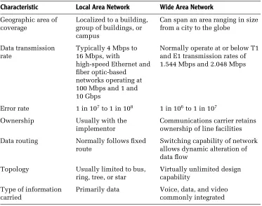
13TABLE 1.1 Comparing LANs and WANs
Characteristic Local Area Network Wide Area Network
Geographic area of coverage
Localized to a building, group of buildings, or campus
Can span an area ranging in size from a city to the globe
Data transmission rate
Typically 4 Mbps to 16 Mbps, with
high-speed Ethernet and fiber optic-based
networks operating at 100 Mbps and 1 and 10 Gbps
Normally operate at or below T1 and E1 transmission rates of 1.544 Mbps and 2.048 Mbps
Error rate 1 in 107to 1 in 108 1 in 106to 1 in 107
Ownership Usually with the implementor
Communications carrier retains ownership of line facilities
Data routing Normally follows fixed route
Switching capability of network allows dynamic alteration of data flow
Topology Usually limited to bus, ring, tree, or star
Virtually unlimited design capability
Type of information carried
Primarily data Voice, data, and video commonly integrated
Peripheral sharing allows network users to access color laser printers, CD-ROM jukebox systems, and other devices that may be needed only a small portion of the time a workstation is in operation. Thus, users of a LAN can obtain access to resources that would probably be too expensive to justify for each individual workstation user.
The ability to access data files and programs from multiple workstations can substantially reduce the cost of software. In addition, shared access to database information allows network users to obtain access to updated files on a real-time basis.
One popular type of application program used on LANs enables users to transfer messages electronically. Commonly referred to as electronic mailor
e-mail, this type of application program can be used to supplement and, in many cases, eliminate the need for paper memoranda.
14
c h a p t e r o n e
personal computer requiring access to a mainframe would require a separate method of access. This might increase both the complexity and the cost of providing access.
Perhaps the most popular evolving use of LANs is to provide a group of computer users with economical access to the Internet. Instead of having a large number of employees obtain individual modem dial-up or ISDN dial access accounts with an Internet service provider (ISP), it is often more economical to connect an organizational LAN to the Internet via a single connection to an ISP. In addition, the connection to the Internet will usually provide a higher transmission capability than obtainable on an individual user basis. Later in this book we will turn our attention to methods that can be used to connect organizational LANs to the Internet, as well as the use of different products to protect organizational computer facilities from Internet users that have no business accessing those facilities.
Technological Characteristics
Although a local area network is a limited distance transmission system, the variety of options available for constructing such networks is anything but limited. Many of the options available for the construction of local area networks are based on the technological characteristics that govern their operation. These characteristics include different topologies, signal-ing methods, transmission media, access methods used to transmit data on the network, and the hardware and software required to make the net-work operate.
Topology
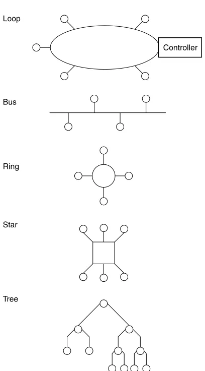
The topology of a local area network is the structure or geometric layout of the cable used to connect stations on the network. Unlike conventional data communications networks, which can be configured in a variety of ways with the addition of hardware and software, most local area networks are designed to operate based on the interconnection of stations that follow a specific topology. The most common topologies used in LANs include the loop, bus, ring, star, and tree, as illustrated in Figure 1.4.
introduction to networking concepts
15Loop
Bus
Ring
Star
Tree
[image:33.536.169.373.79.447.2]Controller
Figure 1.4 Local area network topology. The five most common geometric layouts of LAN cabling form a loop, bus, ring, star, or tree structure.
16
c h a p t e r o n e
placement of network control in the controller. If the controller failed, the entire network would become inoperative. Due to these problems, the use of loop systems is restricted to several niche areas, and they are essentially considered a derivative of a local area network.
Bus In a bus topology structure, a cable is usually laid out as one long branch, onto which other branches are used to connect each station on the network to the main data highway. Although this type of structure permits any station on the network to talk to any other station, rules are required for recovering from such situations as when two stations attempt to communicate at the same time. Later in this chapter, we will examine the relationships among the network topology, the method employed to access the network, and the transmission medium employed in building the network.
Ring In a ring topology, a single cable that forms the main data highway is shaped into a ring. As with the bus topology, branches are used to connect stations to one another via the ring. A ring topology can thus be considered to be a looped bus. Typically, the access method employed in a ring topology requires data to circulate around the ring, with a special set of rules governing when each station connected to the network can transmit data.
Star The fourth major local area network topology is the star structure, illustrated in the lower portion of Figure 1.4. In a star network, each station on the network is connected to a network controller. Then, access from any one station on the network to any other station can be accomplished through the network controller. Here, the network controller functions like a telephone switchboard, because access from one station to another station on the network can occur only through the central device. In fact, you can consider a telephone switchboard or PBX as representing a star-structured LAN whose trunks provide connections to the wide area network telephone infrastructure.
introduction to networking concepts
17of many cable TV systems to two-way amplifiers and the support of digital transmission, the local cable TV infrastructure can be considered to represent an evolving type of tree-structured local area network.
Mixed Topologies Some networks are a mixture of topologies. For example, as previously discussed, a tree structure can be viewed as a series of inter-connected buses. Another example of the mixture of topologies is a type of Ethernet known as 10BASE-T, which is described in detail in Chapter 3. That network can actually be considered a star-bustopology, because up to 16 or 24 devices known as stations are first connected to a common device known as a hub, which in turn can be connected to other hubs to expand the network.
Comparison of Topologies
Although there are close relationships among the topology of the network, its transmission media, and the method used to access the network, we can examine topology as a separate entity and make several generalized observations. First, in a star network, the failure of the network controller will render the entire network inoperative. This is because all data flow on the network must pass through the network controller. On the positive side, the star topology normally consists of telephone wires routed to a LAN switch. A local area network that can use in-place twisted-pair telephone wires in this way is simple to implement and usually very economical.
In a ring network, the failure of any node connected to the ring normally inhibits data flow around the ring. Due to the fact that data travels in a circular path on a ring network, any cable break has the same effect as the failure of the network controller in a star-structured network. Because each network station is connected to the next network station, it is usually easy to install the cable for a ring network. In comparison, a star network may require cabling each section to the network controller if existing telephone wires are not available, and this can result in the installation of very long cable runs.
18
c h a p t e r o n e
failure in a ring network. However, some local area networks, such as Token-Ring and FDDI, were designed to overcome the effect of certain types of cable failures. Token-Ring networks include a backup path which, when manually placed into operation, may be able to overcome the effect of a cable failure between hubs (referred to asmultistation access unitsorMAUs). In an FDDI network, a second ring can be activated automatically as part of a self-healing process to overcome the effect of a cable break.
A tree-structured network is similar to a star-structured network in that all signals flow through a common point. In the tree-structured network, the common signal point is the headend. Failure of the headend renders the network inoperative. This network structure requires the transmission of information over relatively long distances. For example, communications between two stations located at opposite ends of the network would require a signal to propagate twice the length of the longest network segment. Due to the propagation delay associated with the transmission of any signal, the use of a tree structure may result in a response time delay for transmissions between the nodes that are most distant from the headend.
Although the first type of Ethernet network was based on a bus-structured topology, other types of Ethernet networks incorporate the use of different topologies. Today you can select bus-based, star-bus, or tree-structured Eth-ernet networks. Thus, you can select a particular type of EthEth-ernet network to meet a particular topology requirement.
Signaling Methods
The signaling method used by a local area network refers to both the way data is encoded for transmission and the frequency spectrum of the media. To a large degree, the signaling method is related to the use of the frequency spectrum of the media.
Broadband versus Baseband
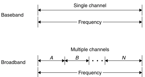
Two signaling methods used by LANs are broadband and baseband. In broad-band signaling, the bandwidth of the transmission medium is subdivided by frequency to form two or more subchannels, with each subchannel permitting data transfer to occur independently of data transfer on another subchannel. Inbaseband signaling, only one signal is transmitted on the medium at any point in time.
introduction to networking concepts
19Baseband
Broadband
Single channel
Frequency
Multiple channels
Frequency
[image:37.536.156.389.87.211.2]A B N
Figure 1.5 Baseband versus broadband signaling. In baseband signaling the entire frequency bandwidth is used for one channel. In comparison, in broad-band signaling the channel is subdivided by frequency into many subchannels.
Figure 1.5 illustrates the difference between baseband and broadband signaling with respect to channel capacity. It should be noted that although a twisted-pair wire system can be used to transmit both voice and data, the data transmission is baseband, because only one channel is normally used for data. In comparison, a broadband system on coaxial cable can be designed to carry voice and several subchannels of data, as well as fax and video transmission.
Broadband Signaling A broadband local area network uses analog technol-ogy, in which high-frequency (HF) modems operating at or above 4 kHz place carrier signals onto the transmission medium. The carrier signals are then modified — a process known as modulation, which impresses information onto the carrier. Other modems connected to a broadband LAN reconvert the analog signal block into its original digital format — a process known as
demodulation.
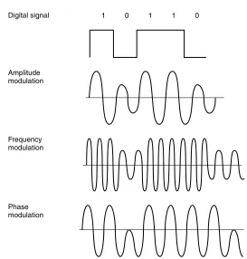
Figure 1.6 illustrates the three primary methods of data encoding used by broadband analog systems: amplitude, frequency, and phase modulation. The most common modulation method used on broadband LANs isfrequency shift keying (FSK), in which two different frequencies are used, one to represent a binary 1 and another frequency to represent a binary 0.
Another popular modulation method uses a combination of amplitude and phase shift changes to represent pairs of bits. Referred to as amplitude modulation phase shift keying (AM PSK), this method of analog signaling is also known as duobinary signaling because each analog signal represents a pair of digital bits.
20
c h a p t e r o n e
Phase modulation Frequency modulation Amplitude modulation
[image:38.536.126.399.79.365.2]Digital signal 1 0 1 1 0
Figure 1.6 Modulation methods. Baseband signaling uses amplitude, fre-quency, or phase modulation, or a combination of modulation techniques to represent digital information.
To provide a bidirectional information transfer capability, a broadband LAN uses one channel for inbound traffic and another channel for outbound traffic. These channels can be defined by differing frequencies or obtained by the use of a dual cable.
Baseband Signaling In comparison to broadband local area networks, which use analog signaling, baseband LANs use digital signaling to convey information.
introduction to networking concepts
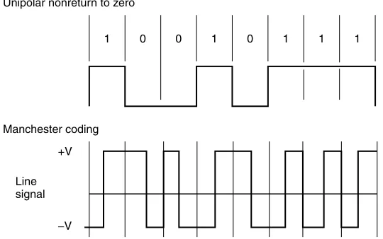
21 [image:39.536.137.407.391.560.2]Because the signal goes from 0 to some positive voltage and does not return to 0 between successive binary 1s, it is referred to as a unipolar nonreturn to zero signal (NRZ). This signaling technique is illustrated at the top of Figure 1.7.
Although unipolar NRZ signaling is easy to implement, its use for trans-mission has several disadvantages. One of the major disadvantages associated with this signaling method involves determining where one bit ends and another begins. For example, if you examine the top portion of Figure 1.7 you will note that the bit sequences ‘‘00’’ and ‘‘111’’ remain at distinct voltage levels. Thus, the ability to recognize that a sequence of two or more pulses of the same value occurred requires synchronization between a transmitter and receiver by the use of clocking circuitry, which can be relatively expensive.
To overcome the need for clocking, baseband LANs use Manchester or
Differential Manchester encoding. In Manchester encoding, a timing transition always occurs in the middle of each bit, while an equal amount of positive and negative voltage is used to represent each bit. This coding technique provides a good timing signal for clock recovery from received data, due to its timing transitions. In addition, because the Manchester code always maintains an equal amount of positive and negative voltage, it prevents direct current (DC) voltage buildup, enabling repeaters to be spaced farther apart from one another.
1 0 0 1 0 1 1 1
Unipolar nonreturn to zero
Manchester coding
Line signal
+V
−V
22
c h a p t e r o n e
The lower portion of Figure 1.7 illustrates an example of Manchester coding. Note that a low to high voltage transition represents a binary 1, while a high to low voltage transition represents a binary 0. A second type of Manchester coding is referred to as Differential Manchester encoding. Under Differential Manchester encoding, the voltage transition is used only to provide clocking. The encoding of a binary 0 or 1 is represented by the presence or absence of a transition at the beginning of each bit period. Refer to Chapter 4 for specific information concerning Manchester encoding on different types of Ethernet networks.
Along with providing users with a choice of topologies, Ethernet also provides a choice of signaling methods. Although most types of Ethernet networks use baseband signaling, a broadband Ethernet is also available. In fact, you can connect baseband- and broadband-based Ethernet networks to satisfy different organizational requirements. Refer to Chapter 3 for specific information concerning the signaling methods used by different Ethernet networks and the hardware components used to construct and interconnect such networks.
Transmission Medium
The transmission medium used in a local area network can range in scope from twisted-pair wire, such as is used in conventional telephone lines, to coaxial cable, fiber-optic cable, and electromagnetic waves such as those used by FM radio and infrared. Each transmission medium has a number of advantages and disadvantages. The primary differences between media are their cost and ease of installation; the bandwidth of the cable, which may or may not permit several transmission sessions to occur simultaneously; the maximum speed of communications permitted; and the geographic scope of the network that the medium supports.
Twisted-Pair Wire
introduction to networking concepts
23Although inexpensive and easy to install, unshielded twisted-pair (UTP) wire is very susceptible to noise generated by fluorescent light ballasts and electrical machinery. In addition, a length of twisted-pair wire acts as an antenna; however, the twists serve as a mechanism to partially counteract this antenna effect. Unfortunately, due to the law of physics, the longer the wire length, the greater the noise it gathers. At a certain length, the received noise will obliterate the signal, which attenuates or decreases in strength as it propagates along the length of the wire. This noise can affect the error rate of data transmitted on the network, although lead-shielded twisted-pair (STP) cable can be employed to provide the cable with a high degree of immunity to the line noise and enable extended transmission distances. In Chapter 3 we will examine a building cabling standard and the various categories of twisted-pair that can support different transmission rates which, in turn, enable different types of Ethernet networks to be supported.
Because the bandwidth of twisted-pair cable is considerably less than coaxial or fiber-optic cable, normally only one signal is transmitted on this cable at a time. As previously explained, this signaling technique is known as baseband signaling and should be compared with the broadband signaling capability of coaxial and fiber-optic cable.
Although a twisted-pair wire system can be used to transmit both voice and data, the data transmission is baseband because only one channel is normally used for data. In comparison, a broadband system on coaxial or fiber-optic cable can be designed to carry voice and several subchannels of data, as well as fax and video transmission. Other constraints of unshielded twisted-pair wire are the rate at which data can flow on the network and the distance it can flow. Although data rates up to 1 gigabit per second (Gbps) can be achieved, normally local area networks employing UTP wiring operate at a lower data rate. In addition, UTP systems normally cover a limited distance, measured in terms of several hundred to a few thousand feet, while coaxial and fiber-optic cable–based systems may be limited in terms of miles. Extending transmission distances over twisted-pair wire requires the periodic insertion of repeaters into the cable. A repeater receives a digital signal and then regenerates it; hence, it is also known as adata regenerator.
Coaxial Cable
24
c h a p t e r o n e
Protective polyethylene jacket
Polyethylene dielectric
Overlapped-seam copper outer
conductor Copper inner conductor
[image:42.536.127.399.88.276.2]Steel strength member
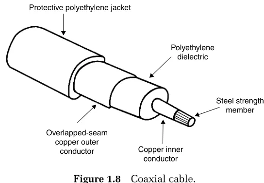
Figure 1.8 Coaxial cable.
composition of a typical coaxial cable; however, it should be noted that over 100 types of coaxial cable are currently marketed. The key differences between such cables involve the number of conductors contained in the cable, the dielectric employed, and the type of protective jacket and material used to provide strength to the cable so it can be pulled through conduits without breaking.
Two basic types of coaxial cable are used in local area networks. The type of cable used is based on the transmission technique employed: baseband or broadband signaling. Both cable types are much more expensive than twisted-pair wire; however, the greater frequency bandwidth of coaxial cable permits higher data rates for longer distances than you can obtain over twisted-pair wire.
Normally, 50-ohm coaxial cable is used in baseband networks, while 75-ohm cable is used in broadband networks. The latter coaxial is identical to that used in cable television (CATV) applications, including the coaxial cable used in a home. Data rates on baseband networks using coaxial cable range from 50 to 100 Mbps. With broadband transmissions, data rates up to and including 400 Mbps are obtainable.
introduction to networking concepts
25easily regenerated by the use of a device known as a line driver or data regenerator. The line driver or data regenerator is a low-cost device that is constructed to look for a pulse rise, and upon detecting the occurrence of the rise, it will disregard the entire pulse and regenerate an entirely new pulse. Thus, you can install low-cost line drivers into a baseband coax-ial network to extend the distance over which transmission can occur on the cable. Typically, a coaxial cable baseband system can cover an area of several miles, and may contain hundreds to thousands of stations on the network.
Obtaining independent subchannels defined by separate frequencies on coaxial cable broadband transmission requires the translation of the digi-tal signals from workstations into appropriate frequencies. This translation process is accomplished by the use of radio-frequency (RF) modems, which modulate the digital data into analog signals and then convert or demodulate received analog signals into digital signals. Because signals are transmitted at one frequency and received at a different frequency, a headend or frequency translator is also required for broadband transmission on coaxial cable. This device is also known as aremodulator, as it simply converts the signals from one subchannel to another subchannel.
Fiber-Optic Cable
Fiber-optic cable is a transmission medium for light energy, and as such, provides a very high bandwidth, permitting data rates ranging up to billions of bits per second. The fiber-optic cable has a thin core of glass or plastic, which is surrounded by a protective shield. Several of these shielded fibers are bundled in a jacket, with a central member of aluminum or steel employed for tensile strength.
Digital data represented by electrical energy must be converted into light energy for transmission on a fiber-optic cable. This is normally accom-plished by a low-power laser, or through the use of a light-emitting diode and appropriate circuitry. At the receiver, light energy must be recon-verted into electrical energy. Normally, a device known as a photo detector, as well as appropriate circuitry to regenerate the digital pulses and an amplifier, are used to convert the received light energy into its original digital format.
26
c h a p t e r o n e
Core
Outer jacket
Kelvar fibers
Buffer coating Cladding
Figure 1.9 Horizontal cross section of a single-strand fiber cable.
outer jacket, which is commonly colored orange, represents a polymer-based shield that protects the cable from the elements.
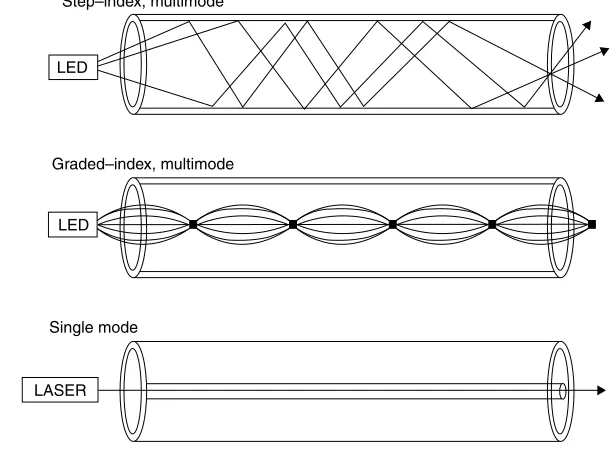
There are two key factors that govern the manner by which light flows through a fiber-optic cable. Those factors are the diameter of the core and the light source. The first type of fiber-optic cable developed had a relatively large diameter that ranged from 50 to 140 microns, where a micron is a millionth of a meter. The original light source used to transmit information was a light-emitting diode (LED). The coupling of an LED to a large-diameter optical fiber results in photons flowing along multiple paths through the optical fiber, resulting in the transmission referred to as multimode, which is also the same name used to reference the type of optical fiber.
There are two types of multimode fiber, referred to as step-index and graded-index. A step-index fiber has a core with a uniform refractive index, resulting in the different components of a light signal in the form of modes or rays flowing in a non-uniform manner through the optical cable. The top portion of Figure 1.10 illustrates the flow of light through a step-index, multimode fiber. In a graded-index multimode fiber, the refractive index is varied from the center to the edge of the core to minimize modal dispersion. The middle portion of Figure 1.10 illustrates the flow of light through a graded-index, multimode fiber. This type of fiber minimizes model dispersion and supports higher data rates than a step-index multimode optical fiber.
A third type of optical fiber has a relatively small core diameter, typically between 7 and 12 microns (10−6meters). This type of optical fiber permits
introduction to networking concepts
27LED
Graded–index, multimode LED
Step–index, multimode
[image:45.536.113.418.95.322.2]LASER Single mode
Figure 1.10 Light flow in multimode and single-mode optical fiber.
a result of the lack of modal dispersion, single mode supports a much higher data rate than multimode fiber. Because of the small diameter of single-mode fiber, lasers are used as the light source instead of LEDs.
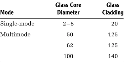
Both the core thickness and the cladding of an optical fiber are measured in microns. The three major core thicknesses used in optical fiber are 50, 62 and 100 microns. The associated claddings for those core diameters are 125, 125 and 140 microns, respectively. Table 1.2 summarizes the relationships between core and cladding diameters for single-mode and multimode fiber.
In trade literature you will note what appears as a ratio in the form of x/y
when the metrics associated with an optical fiber are referenced. In actuality, this is not a ratio but instead references the core and the cladding thickness of an optical fiber in microns. Thus, 50/125 would, for example, reference an optical fiber whose core diameter is 50 microns and whose cladding diameter is 125 microns.
28
c h a p t e r o n e
TABLE 1.2 Common Core and Cladding Diameters of Optical Fiber in Microns
Mode
Glass Core Diameter
Glass Cladding
Single-mode 2–8 20
Multimode 50 125
62 125
100 140
Similarly, fiber-optic cable can be installed through areas where the flow of electricity could be dangerous.
Because most fibers provide only a single, unidirectional transmission path, a minimum of two cables is normally required to connect all transmitters to all receivers on a network built using fiber-optic cable. Due to the higher cost of fiber-optic cable, the dual cable requirement of fiber cables can make them relatively expensive in comparison with other types of cable. In addition, until recently it was very difficult to splice fiber-optic cable, and sophisticated equipment and skilled installers were required to implement a fiber-optic-based network. Similarly, once this type of network was installed, until recently it was difficult to modify the network. Recent advances in fiber transmission through the use of wavelength division multiplexing enables two or more transmission paths separated by the frequency of light to be carried on a common optical cable. Although wavelength division multiplexing is being used in the long-distance fiber backbones of communications carriers to increase the transmission capacity of their infrastructure, the cost of electro-optical transmitter receivers to support this technology usually precludes its use with local area networks.
introduction to networking concepts
29whose data rate normally requires the use of optical fiber as a transport medium. Although Gigabit Ethernet can operate on copper conductors, its transmission distance is limited in comparison to when optical fiber is used. With the declining cost of the fiber-optic cable and fiber-optic components, and the continued introduction of improvements that simplify the installation and modification of networks using this type of cable, the next few years may bring a profound movement toward the utilization of fiber optics throughout local area networks.
Ethernet can be categorized as a network for everyone, because of its support of multiple topologies, signaling methods, and transmission media. In addition to twisted-pair and coaxial cable-based Ethernet networks, you can also extend the transmission distance of such networks by the use of fiber-optic cable. Thus, the old adage from a presidential campaign, ‘‘a choice not an echo,’’ is highly relevant to Ethernet networks.
Access Method
If the topology of a local area network can be compared with a data highway, then the access method might be viewed as the set of rules that enable data from one workstation to successfully