AN AUTOMATIC HIGH PRECISION REGISTRATION METHOD BETWEEN LARGE
AREA AERIAL IMAGES AND AERIAL LIGHT DETECTION AND RANGING DATA
Quanye Du a, *, Deming Xie b , Yushan Sun a ,
a
Chinese Academy of Surveying and Mapping(CASM), Beijing, China, [email protected], [email protected]
b Geological Exploration Technolgy Institute Of Jiangsu Province,Nanjing,China, [email protected]Commission I
KEY WORDS:
aerial images, aerial light detection and ranging data, image matching point cloud, aerotriangulation,
single image spatial resection, registration
ABSTRACT:
The integration of digital aerial photogrammetry and Light Detetion And Ranging (LiDAR) is an inevitable trend in
Surveying and Mapping field. We calculate the external orientation elements of images which identical with LiDAR
coordinate to realize automatic high precision registration between aerial images and LiDAR data. There are two ways
to calculate orientation elements. One is single image spatial resection using image matching 3D points that registered
to LiDAR. The other one is Position and Orientation System (POS) data supported aerotriangulation. The high
precision registration points are selected as Ground Control Points (GCPs) instead of measuring GCPs manually
during aerotriangulation. The registration experiments indicate that the method which registering aerial images and
LiDAR points has a great advantage in higher automation and precision compare with manual registration.
* Corresponding author
1. INTRODUCTION
1.1 General Instructions
To realize integrating digital photogrammetry and LiDAR, one of key issues is to realize automatic high precision registration between aerial images and LiDAR data. That means every LiDAR point can be projected to image position, and every image point can be find the nearest corresponding LiDAR point.
In general, a registration process has three major components to be considered, mainly; the registration primitives, the transformation function that mathematically relates the datasets under consideration using the extracted primitives, and finally the similarity measure which ensures the coincidence of conjugate primitives after applying the transformation function (Ghanma, 2006). In Ghanma’s thesis, the integration method of aerial and LiDAR data which straight lines as the registration primitives was introduced.
Usually, the corresponding point is think about firstly. It is showed LiDAR points and aerial images, find the corresponding points, and described relationship LiDAR and images using transformation function. It is difficult to find corresponding point in this method manually. More importantly, it is lowly automated. Certainly, automatic matching corresponding points between LiDAR and images have been researching.
Some feature points of building were used by doctor Zhong (Zhong, 2009). The projection relationship between building and LiDAR and images is described by 6-truples relaxation.
Two methodologies were introduced that utilize straight-line and areal features derived from both datasets as the primitives (Habib, 2006). The first methodology directly incorporates LiDAR lines as control information in the photogrammetric triangulation, while in the second methodology, LiDAR patches are used to geo-reference the photogrammetric model. However, the corresponding 2D straight lines extracted from images were manual. Wu bo also used planar feature as registration primitives (Wu,2006).
Deng fei matched two images, and registered matching points to LiDAR points using Iterative Closest Point (ICP) Algorithm. Finally, he calculated the orientation elements of images using 3D points registered to LiDAR (Deng,2006). It is proved that using matching points to registered images and LiDAR is practicable.
The integration of sensor is one of important integration approaches. Such as RIEGL VZ-1000 which come out in 2013, it is the integration of 3D terrestrial scanner and professional camera. Leica’s Airborne LiDAR System (ALS60,ALS70,ALS80) have been equipped with aerial camera, but it’s images and LiDAR points were not be registered.
2. METHOD
2.1 Key points
collinearity equations
Traditional photogrammetry is based on feature points and imaging equations of central projection, namely collinearity equations, which are one of important equations in photogrammetry (Wang, 2007). It describes accurately the relationship between the ground point and it’s image point. In this paper, collinearity equations are adopted to describe the corresponding relationship between LiDAR point and aerial image. According to camera model, image point
images matching 3D points
After comprehensive consideration, we take images matching 3D points as the registration primitives. Normally two main classes of matching primitives can be differentiated: image intensity patterns and features. It is also called area-based matching and feature-based matching. In this paper, Zhangli’s matching method was taken. The approach essentially consists of several mutually connected components: the image pre-processing, the multiple primitive multi-image (MPM) matching, the refined matching and the system performance evaluation. Each of them is important and possesses particular features, which are fully described in different parts of the Zhangli’s dissertation (Zhang, 2005). After corresponding image points find out, the coordinates of image point are calculated by forward intersection using collinearity equations. Finally, images matching 3D points are carried out.
ICP
Iterative Closest Point Algorithm (ICP) was presented by professor Besl (Besl, 1992). It describes a general-purpose, representation-independent method for the accurate and computationally efficient registration of 3-D shapes including free-form curves and surfaces. The method handles the full six degrees of freedom and is based on the iterative closest point (ICP) algorithm, which requires only a procedure to find the closest point on a geometric entity to a given point. The ICP algorithm always converges monotonically to the nearest local minimum of a mean-square distance metric, and the rate of convergence is rapid during the first few iterations. The ICP algorithm is used to register two laser point data. In this paper, ICP is used to register LiDAR points and 3D image points. Some test result has been shown that it is also highly effective.
single image spatial resection
Single image spatial resection means that calculating the external orientation elements of images by GCPs and their corresponding image points. In this paper, image matching 3D
points which registered to LiDAR were taken as GCPs. Unit quaternion was adopted during calculating. It represents rotation. Based on the least square principle, the closed-form solution to unit quaternion is solved out first. Then the rotation matrix is obtained, and angular elements are derived. Lastly coordinates of projective centre is computed (Guan,2008).
2.2 Data Processing Flow
There are two data processing flows for registration of two kinds of data. One is One by One, the other is aerotriangulation.
one by one
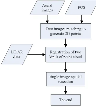
One by one means that matching two images in turn firstly. Then single image 3D points are registered to LiDAR using ICP. Finally, the external orientation elements of every image are calculated by single image spatial resection. The data processing flow is showed in Figure 1.
Figure 1. Data processing flow of one by one
aerotriangulation
This data processsing flow is based on aerotriangulation operation flow. In the first, the Position and Orientation System (POS) data is taken as the initial exterior orientation elements of the images, and tie points of aerotriangulation are extracted automatically assisted with POS and the free net is constructed. Secondly, some local area image are selected as control images, and image points is acquired by multi-images dense matching under constraint of LiDAR data. Finally, after registration of two kinds of points some control points are selected, and bundle adjustment is carried out to resolve orientation elements. IF the result is not meets precision, 3D image points are regenerated by new orientation elements. If the result meets precision or arrives at maxmum iteration number, it is the end.The iterative algorithm is applied during processing. In each iterative operation, 3D coordinates of image matching points are regenerated with the last orientation parameters of images after adjustment, the key corresponding points of the two point clouds are reselected by the nearest distance. After taking high precision registration points as control points for bundle block adjustment, the new orientation elements of images are carried out. This data processing flow is showed in Figure 2.
Figure 2. Data processing flow of aerotriangulation
3. EXPERIMENT A 3.1 Test Data Introduction
The test data was acquired by Toposys. The mean flying height was 900m above ground. The interval of laser footprint is about 1.0m, and image’s resolution is about 0.2m, and pixel size is 0.0068mm. The overlap between two images is about 60%. The images are showed in Figure 3. The LiDAR data is showed in Figure 4.
Figure 3. images overview.
Figure 4. LiDAR overview.
3.2 Image matching
After extracting dense Harris feature points, two images matching under constraint of LiDAR and initial orientation elements is put into practice. Figure 5 shows the image matching 3D points.
Figure 5. image matching points
3.3
single image spatial resection
After registering image 3D points to LiDAR using ICP, the external orientation elements of every image are calculated by single image spatial resection. Table 1 shows the Root Mean Square Error (RMS Error) result of every image.
The image number RMS error (mm)
the second image the third image the fourth image the fifth image
0.00536 0.00751 0.01385 0.03342
Table 1. precision of single image spatial resection
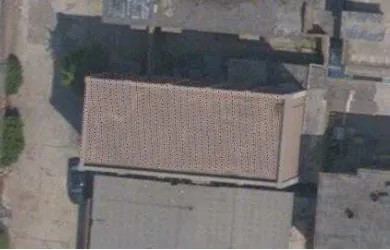
There are very little image matching points in first image and the sixth one. So we give up them. There is some water area in fifth image. This lead to the precision of the fifth image is not high. However, the result that Digital Line Graphic (DLG) which from LiDAR registered to the Digital Orthophoto Map (DOM) is very good, as showed in figure 6.
Figure 6. result of DLG and DOM
4. EXPERIMENT B
4.1 Test Data Introduction
The test data was acquired by Leica Geosystems Proprietary Airborne Laser Scanning ALS50-II. The mean flying height was 500m above ground. The interval of laser footprint is about 0.4m, and image’s resolution is about 0.1m, and pixel size is 0.0068mm. There were 3 strips and 24 images.
P1 P2 P3 P4 P5 P6
P1-P2 P2- P3 P3-P4 P4-P5 P5- P6
4.2 Image matching
According to the plan of setting GCPs during aerial photogrammetry, as Figure 7 shows that six images are taken as control ones.
Figure 7. control images (the red triangle)
Then multi-images matching under constraint of LiDAR and initial orientation elements is put into practice. Finally high precision image matching 3D points are acquired. Figure 8 shows the result of image matching (only over six-overlapping points).The corresponding LiDAR points are showed in Figure 9.
Figure 8. The image matching 3D points of control images
Figure 9. The corresponding LiDAR points
4.3 Adjustment
After registering two kinds of points, bundle adjustment is carried out with some registration points as control points. Table 2 shows the Root Mean Square Error (RMS Error) result of every iteration adjustment.
Iteration number RMS error (mm)
the first iteration the second iteration the third iteration the fourth iteration the fifth iteration the sixth iteration
0.00639 0.00624 0.00621 0.00619 0.00618 0.00618 Table 2. RMSE during adjustment iteration
There are four check points in survey area. The residual error of check points on X,Y and Z direction is showed in table 3 after four times iteration.
Check point name dX dY dZ
CH01 CH02 CH03 CH04
0.23 -0.07 0.34 -0.08
0.19 0.26 0.28 0.40
-0.10 0.11 -0.32 0.05 Table 3. Residual error of check points
4.4 Other results
LiDAR points projected
In order to verify the result of registration furthermore, some roof LiDAR points of bungalow are separated, and they are projected on aerial image with final orientation elements. Figure 10 and Figure 11 shows the results of two roof LiDAR points projected.
Figure 10. roof LiDAR points projected result
Figure 11. roof LiDAR points projected result The International Archives of the Photogrammetry, Remote Sensing and Spatial Information Sciences, Volume XL-7/W4, 2015
DOM
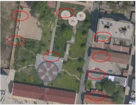
DOM can also displays the result of registration. Figure 12 shows that the local DOM with POS before two kinds of data registration, and Figure 13 shows the result of the same DOM after registration. It is obvious that the DOM after registration is better than before.
Figure 12. Local DOM before registration
Figure 13. The same local DOM after registration
5. CONCLUSIONS
The registration experiments are indicated that after calculating the external orientation elements of images identical with LiDAR coordinate, then automatic high precision registration between aerial images and LiDAR data is realized. This is good foundation for 3D city model constracting using two kinds of data.
ACKNOWLEDGEMENTS (OPTIONAL)
This work is supported by the Special Fund by Surveying & Mapping and Geoinformation Research in the Public Interest (201412010), the basic surveying and mapping project with
project number A1504 and Basic Science Research Foundation of CASM with project number 7771523.
REFERENCES
Zhong, Ch., 2004. A Study on LiDAR Data Aided High-quality True Orthoimage Generation.Wuhan:Wuhan University Ph.D. Disssertation.
Besl, Paul J.,Neil D. Mckay., 1992. A method for registration of 3-D shapes, IEEE Transactions on Pattern Analysis and Machine Intelligence, 14(2), pp. 239-256.
Ghanma, Mwafag., 2006. Integration of photogrammetry and LIDAR. Calgary:University of Calgary (Canada).Ph.D. dissertation.
Habib, A. F., S. Shin, et al., 2006. Integration of Photogrammetric and LIDAR Data in a Multi-Primitive Triangulation Environment. Innovations in 3D Geo Information Systems,pp. 29-45.
Wang, ZH.ZH., 2007. principles of Photogrammetry (in Chinese), Wuhan,Wuhan university press, pp.20-21.
Zhang, L., 2004. Automatic Digital Surface Model (DSM) Generation from Linear Array Images. Zurich:Swiss Federal Institute of Technology Zurich.Ph.D. Disssertation.
Wu, B., 2006.A Reliable Stereo Image Matching Method Based on Self-adaptive Triangle Constraint.Wuhan:Wuhan University Ph.D. Disssertation.
Deng, F., 2006.Research on LIDAR and Digital Images Registration and Objects Extraction.Wuhan:Wuhan University Ph.D. Disssertation.
GUAN, Y.L., Cheng, X.J.,et al.,2008.A Solution to Space Resection Based on Unit Quaternion. ACTA GEODAETlCA et CARTOGRAPHICA SINICA,37(1),pp.30-35