TUGASAKHIR
LS 1336
·£\ ..
~]
1¥
ITS
SCHEME OF HULL CORRECTIVE MAINTENANCE
MODULE FOR MANAGEMENT DECISION SUPPORT
USING MICROSOFT VISUAL BASIC
()..JSP
9d-
3>.gLf
CWftl(/
J'
_.I---
cM-cb
P!RPUSTAKAA.
I T S
.,.____---.---~
T11. Teri,.• i 1 (; ~ I - Zc.. ~ } T .. ri ... I ·•~ r~
---r-
·-By :
--·--- -i--' -~~~No. Are ada Prp.
PEVI W AHYUDI " " " " "
-4201.100.028
MARINE ENGINEERING DEPARTMENT
MARINE
TECHNOLOGY FACULTY
SEPULUH NO PEMBER INSTITUTE OF TECHNOLOGY
LEMBARPENGESAHAN
TUGASAKHIR
SCHEME OF HULL CORRECTIVE MAINTENANCE
MODULE FOR MANAGEMENT DECISION SUPPORT
USING MICROSOFT VISUAL BASIC
TUGASAKHIR
(LS 1336)
Diajukan Guna Memenubi Sebagian Persyaratan
Untuk Memperoleh Gelar Sarjana Teknik
Pad a
Jurusan Teknik Sistem Perkapalan
Fakultas Teknelogi Kelautan
Instit11t Teknologi Sepuluh Nopember
Surabaya
Dosen Pembimbing I
Surabaya, Januari
2006Mengetabui
I
Menyetujui
Dosen Pembimbing
II
Dr. Ketut Buda Artana, ST. MSc
NIP.
132 125 668FAKULTASTEKNOLOGIKELAUTAN-ITS
JURUSAN TEKNIK SISTEM PERKAPALAN
KAMPUS ITS KEPUTm SUKOLILO SURABAYA 60111 TELP.5994754, 5994251-55 PES 1102 FAX 5994754
SURA T KEPUTUSAN
PENGERJAAN TUGAS AKHIR
(LS 1336)
Sebagai salah satu syarat untuk mendapatkan gelar Sarjana Teknik pada Jurusan Teknik Sistem Perkapalan, Fakultas Teknologi Kelautan ITS, maka perlu diterbitkan Surat Keputusan Pengerjaan Tugas Akhir yang memberikan tugas kepada mahasiswa tersebut dibawah untuk mengerjakan Tugas sesuai judul dan lingkup bahasan yang telah ditentukan.
Nama Mahasiswa Nrp.
Dosen pembimbing
Tanggal Diberikan Tugas Tanggal Diselesaikan Tugas Judul Tugas Akhir
Dosen Pembimbing I
Pevi Wahyudi 4201 100 028
l. Dr. Ketut Buda Artana, ST, MSc 2. R.O. Saut Guming, ST, MSc.
SCHEME OF HULL CORRECTIVE MAINTENANCE MODULE FOR MANAGEMENT DECISION SUPPORT USING MICROSOFT VISUAL BASIC.
Yang menerima tugas, Mahasiswa
Dr.Ir. Ketut Buda Artana, MSc. R.O. Saut G ing, ST, MSc. Pevi Wahyudi Nrp. 4201 100 028
Nip.l32125668 Nip. 132 133 980
Surabaya, Januari 2005
Teknik Sistem Perkapalan
ABSTRAK
Sistem perawatan korektif untuk lambung kapal harus dilaksanakan seefisien dan seefektif mungkin. Proses pemindahan data dan informasi dari kertas kerja satu ke yang lain menyita banyak waktu dan energi. Dalam pemindahan jumlah data yang besar, kemungkinan tetjadinya kesalahan akibat faktor manusia menjadi lebih besar. Ketika pengolahan data untuk pengambilan keputusan menjadi rumit, hal ini perlu sebuah pendekatan yang sistematik untuk manajemen informasinya. Perusahaan pelayaran memerlukan suatu dukungan teknologi informasi yang cepat dat teliti untuk membantu analisa dalam pengambilan keputusan manajerial.
Solusi untuk jaminan kerapian dokumentasi perawatan kapal ialah dengan menggunakan komputerisasi sistem database perawatan lambung. Modul Perawatan Korektif untuk lambung kapal dapat membantu pengumpulan, penyimpanan, pembaharuan, pengolahan data perawatan lambung kapal dan prediksi perawatan. Dalam fungsinya untuk membantu keputusan manajerial, maka modul ini membantu memberikan penilaian kegagalan dari laporan kegagalan untuk menentukan tingkat kegagalan dan status perbaikan; cargo data memberikan informasi mengenai perkiraan pendapatan untuk setiap petjalanan; dan outsource data telah memberi informasi seperti down time, perkiraan biaya dan faktor ketersediaan. Itu semua, akan membantu pihak manajemen untuk memilih outsource yang terbaik, untuk aktivitas perawatan kapal. Dalam tugas akhir ini, penulis menggunakan Microsoft Visual Basic dan Microsoft SQL Server
untuk membangun sistem database perawatan lambung kapal.
Oleh karena itu dengan implementasi dari perangkat lunak ini, memungkinkan penyimpanan dan pencarian data efisien dibanding dengan menggunakan banyak kertas keija. Modul ini juga membantu akses data dari beberapa orang yang terlibat dalam perawatan lambung kapal..
Kata kunci: Modul Perawatan Korektif untuk lambung, Database Perawatan,
ABSTRACT
Corrective Maintenance System for hull should be executed efficiently and effectively. Evacuation process of data and information in Fleet Division, from
one worksheet to the other will confiscate of time and energy. In transferring amount of data, the human error probability becomes bigger than a few data.
When the data processing for decision support was overwhelming, thus necessitating a systematic approach to information management. Shipping company requires an information technology support for quickly and accurately
analysis in management decision making.
The solution for neatly maintenance documentation guarantee is using a
computerize maintenance database system. The Hull Corrective Maintenance Module assists to corrective maintenance data collection, recording, storing, updating, processing and forecasting. At the function to assist the management decision, this module would give a failure assessment from failure report to
determine whether the failure level and repair status; cargo data had given an information concerning the income estimation for every trip; and outsource data had given any information such as down time, cost estimation, and availability
factor. That all, will assists the management personnel to choose the best outsource, which use for maintenance activity. In final project activities, the author using Microsoft Visual Basic and Microsoft SQL Server to construct the
hull maintenance database system.
Therefore by implementation of this software, perhaps the depository and data seeking more efficient than using a lot of paper sheet. Hull Corrective
Maintenance Module also assists the data access from many persons related in hull maintenance connection.
Keywords: Hull Corrective Maintenance Module, Maintenance Database,
PREFACE
All of the honor, praise and glory belong to my Almighty God, for HIS strength, power, mercy, love and all that HE has done unto me until I could finished my final project. Actually, I am nothing without HIM. My final project has the following title:
SCHEME OF HULL CORRECTIVE MAINTENANCE FOR MANAGEMENT DECISION SUPPORT
USING MICROSOFT VISUAL BASIC
This final project was arranged as a requirement of Bachelor Degree graduation in Marine Engineering Department, Marine Technology Faculty, Sepuluh Nopember Institute of Technology, Surabaya.
The author has realized this final project is a far way from perfection. Therefore, the author hope is a suggestion and development criticism will be given for this final project. For this opportunity, the author would give thank to every person that involved in finishing my final project.
1. Mr. Dr. Ketut Buda Artana, ST, MSc. as my final project counselor who has given the precious motivation, direction, knowledge and all that I can't mentioned it one by one, unto me for my final project.
2. Mr. R. 0. Saut Gurning, ST, MSc. as my final project counselor and college supervisor who has given the precious motivation, direction, knowledge, prayer and all that I can't mentioned it one by one, unto me for my final project.
3. Mr. Ir. Dwi Priyanta, M.SE as a RAMS Subject Coordinator who has given the precious motivation, direction, knowledge and all that I can't mentioned it one by one, unto me for my final project.
...
__________ __
5. Every Marine Engineering Department lecturers who have gtven the
precious direction and knowledge as long as my study time in Marine Engineering Department.
6. Every Marine Engineering Department staffs who have given much of
assist as long as my study time in Marine Engineering Department.
7. My beloved Mom and Dad in Madiun City who have given an example
how to survive and conquer this life. Thank for your love, passion, attention, education and prayer in every breath that I take.
8. My beloved Brother in memoriam, for your life shared in the past that strengthen me until now.
9. My boarding house friends what have come to my brother friend during this time, given some aids and motivation to the author in Final Project. 10. All of my friends in PMK - ITS (Lidia, Esther, Connie, Beatrice, Harrie,
Richard, Ega, Roy and others) for your understanding, passiOn, motivation, prayer and joyful that have been given unto me.
11. All of my friends in PAW Department (Nandy, Edwin, William and
others) for your understanding, motivation, prayer and joyful that have been given unto me.
12. All of my friends in Harvest Satellite (Henry, Laorent, Ema , Mruja,
Sindhu and others) for your medicine when I was sick, understanding, motivation, prayer and joyful that have been given unto me.
13. All of my friends in Reliability & Safety Laboratory that have gtven support for me to finish my project work.
14. All of my friends in Marine Engineering Department, especially 2001ers
that I can not mention it one by one, for support, spirit and help. 15. Other related person that I can't mention it one by one.
And at the end the author hope that this final project can give benefit, knowledge and information to everyone that read this final project.
Surabaya, January 2006
Lembar Pengesahan
Surat Keputusan
CONTENTS
Abstrak ... .
Abstract ... ii
Preface... iii
Contents . . . . .. . .. . .. . . . .. . ... . . . ... . . ... . . . ... . . . ... . . . ... ... . . .. . . ... .. . .. . .. ... . . .. . ... . . . ... . .. . . .... vi
Picture List ... vii
CHAPTER I INTRODUCTION
1.1 Background. . . . .. . ... . . .. .. . ... . . ... . .. . ... . . . ... . . . ... .. . ... . . . ... .. ... .. ... . . . ... ... . . 1-1
1.2 Problem Formulation ... 1-4
1.3 Writing Purpose ... 1-5
1.4 The Benefit of Final Project Result... 1-5
CHAPTER II THEORETICAL BASED
2.1 General ... 2-1
2.2 Hull Construction Failure ... 2-1
2.3 Hull Maintenance Software ... 2-2
2.4 Database Management System ... 2-3
2.5 Entity Relationship Modeling ... 2-7
2.6 Microsoft Visual Basic 6.0 ... 2-15
2. 7 Computerize Maintenance Management System ... 2-16
CHAPTER III METHODOLOGY
3.1 General ... 3-1
3.2 Study of Literature ... 3-2
3.4 Data Processing ... 3-3
3.5 Hull Corrective Maintenance Module Designing ... 3-4
3.6 Mechanism Process ofDecision Making ... 3-7
3. 7 Software Implementation ... 3-1 0
3.8 Frame ofthe Conclusion ... 3-12
CHAPTER IV SCHEME OF SOFTWARE
4.1 General... 4-1
4.2 Model of Software Scheme ... 4-2
4.3 The Scope of Hull Maintenance System ... 4-3
4.4 The Business Process of Corrective Maintenance ... 4-5
4.5 Constructing the Entity Relationship Diagram ... 4-18
4.6 Physical Table Design ... 4-24
4.7 User Interface Design ... 4-27
4.8 Source Code Program ... 4-36
CHAPETR V CONCLUSION AND SUGGESTION
5.1 Conclusion ... 5-1
5.2 Suggestion ... 5-2
BIBLIOGRAPHY
PICTURE LIST
4 . 20 Physical table cargo data & quay time form in Microsoft SQL Server ... 4-25 4 . 21 Physical table monitoring report & repairwork detail in
Microsoft SQL Server ... .4-25
4 . 22 Physical table failure assessment, insurance agreement,
maintenance history & FMEA form in Microsoft SQL
Server ... 4-26 4 . 23 Physical table ship repair list & ship repair list detail form in
Microsoft SQL Server ... 4-26
4. 24 User Interface Corrective Main Menu create using Visual
Basic 6 ... 4-27
4 . 25 User Interface Inspection Report Input Data Menu create
using Visual Basic 6 ... 4-28
4. 26 User Interface Failure Report Input Data Menu create using
Visual Basic 6 ... 4-28
4. 27 User Interface Material Report Detail Input Data Menu create
using Visual Basic 6 ... .4-29
4 . 28 User Interface Repair Work Detail Input Data Menu create
using Visual Basic 6 ... .4-29
4. 29 User Interface Repair List Outsource Input Data Menu create
using Visual Basic 6 ... .4-30
4. 30 User Interface Repair Work Detail Input Data Menu create
using Visual Basic 6 ... .4-30
4 . 31 User Interface Ship Master Menu create using Visual Basic 6
··· 4-31
4. 32 User Interface Superintendent Menu create using Visual
Basic 6 ... 4-31
4. 33 User Interface Ship Manager Menu create using Visual Basic
6 ... 4-31
4. 34 User Interface FMEA Form Input Data Menu create using
4. 35 User Interface Quay Time Data Menu create using Visual Basic 6 ... 4-32
4. 36 User Interface Inspection Report Data Search menu create
using Visual Basic 6 ... .4-33
4 . 3 7 User Interface Inspection Report Detail Data Search menu
create using Visual Basic 6 ... 4-33
4 . 3 8 User Interface Repair Work Detail Data Search menu create
using Visual Basic 6 ... .4-34
4. 39 User Interface Material Report Detail Data Search menu
create using Visual Basic 6 ... 4-34
4. 40 User Interface Repair Work Detail Data Search menu create
using Visual Basic 6 ... ... ... ... .4-35
4. 41 User Interface Maintenance History Data Search menu create
using Visual Basic 6 ... .4-35
4 . 42 Properties Tool for Assistant Superintendent Form .... .4-36
1.1
Background
CHAPTER I
INTRODUCTION
Hull Maintenance System should been executed efficiently and
effectively. Therefore, require the existence of adequate operational data
system. Information technology support for the operation control data, be
needed to make quickly and accurately analysis in management decision
making for the shipping company.
The aim of ship maintenance ts to assist the shipping company
management can fulfilled the conditions of safety policy, environmental
protection and regulations from international classification society. Shipping
company is obliged to fulfill one of policy from IMO (International Maritime
Organization) that is about released the ISM (International Safety
Management) Code to take care commitment of management. Because this
matter represent the condition to obtain DOC (Documents of Compliance) for
the company and SMC (Safety Management Certificate) for the ship. Because
of that, every data of maintenance have to be manageable efficiently and
effectively for management report.
In actually, data traffics especially in armada division were solid enough.
process of data and information from one worksheet to the other will
confiscate of time and energy. In transferring amount of data the human error
probability becomes bigger than a few data.
Usage computerize system in keeping maintenance report, was also felt
maximal less used, it is caused by registered in different various program.
With insufficient tool, a Fleet Manager will obtain difficulties in determining
decision as quickly and precisely for repair status. And existence about
tradition of concerning ships maintenance, that only pursuant to decision
maker experience (Fleet Manager), so when commutation of Fleet Manager
will be happened, processed the experience transfer wouldn't maximal.
Therefore, need a good management of change. Every decision taken for ship
maintenance not only influences the ship operational, but also has truly impact
for the earnings of shipping company.
The solution to guarantee the neat maintenance documentation is using
software, which can update the every step from process of ship maintenance
with the newest data. Where Hull Maintenance Management is representing an
innovative solution for the inspection arrangement and ship repair strategies.
The focus from Hull Maintenance Management is integrity of hull life cycle
owned to cover the inspection strategies and periodical maintenance. When
detailed inspections have been already done, the inspection result required
follow up step by shipping company management.
The Fleet Manager needed a tool, which can assist in conducting its
maintenance. Using Hull Corrective Maintenance Module for Management Decision Support which its function is make some assessment from non conformities report to determine whether the damage represented Minor Work or Major Work requiring furthermore action and finally to determine the repaired status. Processing the scheme development paradigm Management Decision Support Software is a group of duty, phase and efficient activity to transform of user requirement to an effective software solution. In represented the activities that happened during the inspection report assessment uses the Microsoft Visual Basic.
Fleet Portal contains the accurate historical data, the transport route, the result of previous inspection, the method and explanation about the previous maintenance and its material. From this information, is expected to assist analyzing condition the Sister Ships (the ships which seen to be own the looking like of hull form), have the corrosion damages at different place. With the existence of accurate information support from inspection report, a Fleet Manager from will be easier to assess the assorted cause of damage or non-conformities which was founded in field.
the existence of periodical inspection, or bring the ship for the docking repair. However the software purchasing expense make expenditure expense will be increase, so that installment factor is competent become the special consideration for shipping company management.
1.2 Problem Formulation
The problem of scheme the Corrective Maintenance Module:
1. How to determine the risk priority number, from an inspection report with this module.
2. How to determine down time period, with historical maintenance data. 3. How to know the relationship between the dock space availability with
the repaired status.
4. What is the impact of Corrective Maintenance Module for hull maintenance application, in the making of good management report concerning the reasonable repair.
Problem definition used in solving of this final duty is: 1. Failure report as an input for Failure Assessment.
1.3 Writing Purpose
In this final project will take some purpose. Intention of study process to be done for:
1. Knowing the way of software scheme by Microsoft Visual Basic for maritime application.
2. Knowing parameter for the managerial decision making of ship repair status
3. Knowing the way of analyzing, non-conformities inspection reports for hull damages.
1.4 The Benefit of Final Project Result
From result of scheme Corrective Maintenance Module obtained the following benefit:
1. With the existence of software scheme use the Microsoft Visual Basic be expected able to depress the expenditure especially for the expense of purchasing and software installment.
2.1 General
CHAPTER II
THEORETICAL BASED
By operating ship, go out to sea to cause the great enough damage potency for hull construction. Work scope to hull cover the body I ship construction I ship husk especially part of below or under load line is inclusive of sea chest. The example damage is: rustiness, gluing of plant and animal go out to sea the, cart, rips the, leakage, deformation, displacement or possible moment of making or repair does not pursuant to going into effect (Sasongko, 1996).
2.2
Hull Construction Failure
Displacement and erosion also result the leakage happening. While because accident factor will enable to the happening of following at husk or construction log or possible also cart. The happening of cart, rip, even leakage to plate of hull construction oblige to change newly as according to guide and classification rule. Dint (dented) and also wave (corrugation) at plate of construction husk can be depicted at Shell Expansion and have to be changed by pursuant to classification (Sasongko, 1996).
According to Sasongko ( 1996) the happening of rustiness at hull construction will result:
• Taking place of rustiness process will result the happening of leakage of plate of husk of ship construction.
• Decreasing of it thick seta leakage oblige to change and repair.
• This repair cost money which do not minimize also will add the cost allocation for the treatment of ship repair and,
• Repair will confiscate the time operate for the ship result the ship earnings will also decrease.
According to Sasongko (1996) inspection at hull construction cover the: • Thick measurement of husk plate and also precisely on course.
• Location inspection and also wide measurement and deepness of deformation of plate of construction husk.
• Inspection to rustiness condition, paint abraded and leakage routinely
2.3
Hull Maintenance Software
Software of this Hull Maintenance is designed for the : optimize of the reporting database, analysing hull condition, assisting organization of management function better with the existence of adequate data support and structure govern the job and also the specification of :from treatment. This system is consisted of the system at ship and office (liner), what organically database transfer by update database (www.dnvsoftware.com).
2.4 Database Management System
And Database Management System represent a group of program to define, to making I storing and database manipulation to assorted of application. Its intention Data manipulation looks for the data (query), data modification (update) and makes the report (Pramana, 2000).
qualitative which also to get the level of damage risk that happened at the time of
inspection (Keyserling, 2000).
In scheme of software of Management Decision Support use the Microsoft
Visual Basic applicative for this time, because most job world still use the
Microsoft Windows (Holzner, 1998). Basic very easy to write the program base
on the Windows. Environmental of Visual Basic programming contain all
medium required to develop the program for the Windows of swiftly and efficient.
Existence of line of menu and toolbar give the amenity to access to all command
controlling this program. ( Halvorson, 2002)
According to Pramana (2000) in designing software there are some activities,
covering:
1. Requirements Analysis and specification
Understand will conducted by that moment system (fundamental
problems) and express in the form of clear and detail.
2. System And software design
Determining correct solution for the fundamental of above problems and
express [it] in an easy form to be translated to a computer program.
3. Implementation I coding
Translating designed by software to a programming language.
4. Testing
Checking software so that as according to requirement wanted and free
5. Operation And maintenance
Repairing any mistake [is] which emerge and improve the facility from
system as according to requirement
The data model gets its inputs from the planning and analysis stage. Here
the modeler, along with analysts, collects information about the requirements of
the database by reviewing existing documentation and interviewing end-users.
The data model has two outputs. The first is an entity-relationship
diagram, which represents the data structures in a pictorial form. Because the
diagram is easily learned, it is valuable tool to communicate the model to the
end-user. The second component is a data document. A document that describes in
details the data objects, relationships, and rules required by the database. The
dictionary provides the detail required by the database developer to construct the
physical database. Database design is defined as: "design the logical and physical
structure of one or more databases to accommodate the information needs of the
Database System
A database system is compilation between database and software for manipulate database.
lJsers!Programmers
DATABASE
SYSTEM Application Programs/Queries
DBMS
SOFTWARE Software to Process Queries!Programs
Stored Database Definition (Meta-Data)
Software to Access Stored Data
Stored Database
Picture 2.1 SimplifY Database System Environment.
The design process roughly follows five steps: 1. Planning and analysis
4. Physical design 5. Implementation
The data model is one part of the conceptual design process. The other, typically is the functional model. The data model focuses on what data should be stored in the database while the functional model deals with how the data is processed. To put this in the context of the relational database, the data model is used to design the relational tables. The functional model is used to design the queries which will access and perform operations on those tables.
2.5
Entity Relationship Modeling
Modeling Data I Data Analysis is technique to comprehend a problems and its complexity as well as to get the information required to solve problem the by seeing the problems from the aspect oflook into the DATA
Some technique of modeling data: 1. Entity Relationship Modeling
Is first time introduced by Chen P. (1976). Most Model data often used in design of database application conceptually, with the focus of data which will be kept.
2. Semantic of Modeling Object
Using concept of class and subclass in modeling data 3. The NIAM ( Nijssen Information Analysis Method)
4. Binary of Modeling Data
Is a data model to orient the graph, where its dots (nodes) is an attribute atomic (simple) and its lines (binary arcs) represented relationship type between two attribute
5. Object-Oriented Modeling
Technique modeling which is pursuant to concept orienting at object (object-oriented) and suited for application using language and database orienting at object.
From all kinds of the data modeling technique, ER Modeling is the most popular during last 2 decades, though latterly start to emerge the other, which can represented of more amount information that is Semantic of Object of Modeling and Object-Oriented Modeling.
What there is ordinary system represented in the form of element (entity) from problems, its characteristic (attribute) and relation/link (relationship) usher the elements.
Phase E.R. Modelling
1. Learning input
2. Design the conceptual model in mind
Notation
An Entity
~
---
. . IdentifierStudent underline
~ _ _ _ . . An Attribute
1 or Property
0 ---•
A RelationshipI
NEnrolment _ ... .__. _ _ _ _ _ _. An Entity
Picture 2.2: Main component in ER Modeling.
Follow the example of the entity:
• student, lecturer, class, study area (in university modeling) • officer, manager, departmental (in white collars modeling) Entity Instances:
• Kindness is instance from entity student
• S 1 Sistem Perkapalan is instance from entity of study area
Weak Entity is entity, which its existence hinges full at existence from other entity. For example, husband I wife from officer are weak entity which its existence base on the entity officer.
Attribute
Attribute is property from entity in the form of information about the entity. For example, entity officer own the following attribute:
• Name • Address • Gender
• NIP (Number of Officer Mains)
Follow the example of the attribute above is ordinary attribute. Others, there are some other type attribute, that is Composite Attribute, that is attribute which is formed by merger of some other attributes. For example: attribute address, coming from merger attribute walked the, town and zip code.
some title at one blow
Identifier (key) special attribute which by unique can be used to identify a An instance from entity. For example:
• NIP [is] key for the entity of officer • NRP [is] key for the entity of student
Relationship
Relationship used to connect two entity or more with the certain meaning. For example incoming Kindness Student [of] majors of area of study of S 1 Sistem Perkapalan Officer Tono put hand to the company X Degree (derajat) from relationship is amount entity participating in the relationship. This Degree can in the form of unary (one entity), binary (two entities, three entities) ... Relationship Binary, which is most commonly, used the Cardinality from relationship used to identify the structure from relationship. For example:
• One To one ( 1:1) • One To many ( 1 :N) • Many To many ( N:M
Advantage of ER Modeling 1. Simple
Loss of ER Modeling
1. Its result can in the form of some alternative model, depended how all analyst I designer comprehend the system.
2. Notation from ER modeling still a lot of variation (less standard).
Summary ER Modelling Notation
Entity
II
II
Weak Entity<>
RelationshipIdentifying Relationship
Key Attribute
Multi valued Attribute
Composite Attribute
... (:::::···.·.::>
···
Derived Attribute
Total Participation of E2 in R
1 N
(min,max)
Structural Constraint (min,max)
Picture 2. 3 Summary ER Modeling Notation
ER diagram:
customer CustAcct account
Data-structure diagram:
customer name street city number balance account
CustD~
/ c c t D a t edate
2.6 Microsoft Visual Basic 6.0
Visual Basic is one of computer language programming. Language
programming is a command that understood by the computer to do certain
duties. Visual Basic language programming that developed by Microsoft since
year 1991, representing development from its predecessor that is BASIC
(Beginners All-Purpose Symbolic Instruction Code) language programming
that developed at 1950. Visual Basic is one kind ofDevelopment Tool that use
to make assorted of computer program, especially a computer program that
used Windows operating system. Visual Basic represent a language
programming that supporting object (Object Oriented Programming= OOP). In
object Oriented Programming (OOP). Window Form of Visual Basic has the
character of the UI (User Interface), which we can develop by using a
peripheral control oftoolbox.
Program that based on Windows have the character of event-driven, it's
mean program that work based to the event that happened to the object in the
program. For example, if a user clicking a knob hence program will give the
"reaction" to the event click. The "reaction" that gives by Program will match
according to the code program (algorithm) that made for event at certain object.
Algorithm from this program will we develop according to ER diagram which
we have made previously, and the table form will we make as easy as possible
2.7 Computerize Maintenance Management System (CMMS)
The objective of maintenance organization is to maximize uptime in most cost effective manner. To accomplish this objective, the following strategies must be clearly specified:
1. Effective maintenance strategies derived from equipment condition and history.
2. Effective techniques for planning and scheduling of work order and utilization of resources.
3. Monitoring of maintenance activities, data collection and performance reporting to support continuous improvement.
These three activities require information about equipment, worker, work orders, jobs, job standards, production schedule and the nature of operations organization. The amount of information that is collected processed and use for decision making is overwhelming, thus necessitating a systematic approach to information management. In, addition, the complexity and uncertainties involved the process of maintenance, engineering and the amount of information handled in a typical maintenance system require computer support. Appropriate computer support provides the means for quick and timely response.
leadership manages all aspect of life in the department. It is essential for
planning, scheduling and controlling the maintenance activities. Through
effective reporting, a CMMS can provide maintenance managers and engineers
with the information needed for sound decision making to control and improve
the maintenance process.
Most organization today has some sort of computerized maintenance
support but may have failed the reap the full benefits of CMMS for the
following reason:
1. In many cases, the system doesn' t meet the maintenance requirements.
2. The system not user friendly.
3. Maintenance planners and engineers are well not trained in using CMMS.
4. CMMS reports are not used for maintenance improvement.
The success of a CMMS can be measured by its availability to support the
maintenance process. Two important elements are essential for an effective
CMMS :
•
Its ability to support the main activities in the maintenance process and,•
The ability the software and hardware configuration of terms of itsreliability ease of use, quality of information and timely processing.
CMMS can be centralized in small organizations or completely
decentralized and distributed in large organization. It can run on main frame,
micro computers, workstations and personal computers. In addition, it can be a
standalone system or part of a network in a client - server environment. A
software can be menu driven or window based. A typical CMMS is linked to inventory, payroll, purchasing and accounting. Experience has shown that the system reliability, timeliness and ease of use enhance the utilization of a CMMS and increase its benefits to the organization.
In terms of support to the maintenance process a CMMS usually includes the following functions:
•
Equipment identification•
Preventive maintenance•
Work order management•
Planning and scheduling•
Inventory control•
Job standards•
Equipment history•
Costs and budgets•
Performance reports•
Quality reportsIn the design process of a CMMS one or more of preceding functions are usually grouped into one module. A CMMS design that supports the previous function is presented, for the example this is work order or request control module serve the following functions:
1. Documenting the process of work request and authorizing the work to be performed.
3. Collecting data about maintenance performance and costs.
4. Providing needed information for feedback and continuous improvements. The work order requires two types of information. The first type is used for planning and scheduling and the second is for identification.
This module initializes the work order by supplying the necessary information regarding new jobs. The categories of information are as follows:
• Work order number • Date
• Problem definition and tool needed
• Equipment number, work plan and location. • Estimated man-hours and costs.
CHAPTER
III
3.1 General
CHAPTER III
METHODOLOGY
To solve the problems of this final project that have been analyzed,
Methodologies represent a base framework that used as a reference. To finish this
final project hence will be used a simulation method, so that all data changes can
be documented better and clearer picture to analysis from the data than manual
The explanation from flowchart above as follows:
3.2 Study of Literature
At this phase will be complete to literature, which there have with reference to maintenance ship (maintenance management process), method study the damage modes and effects (with FMEA) also technique study to design software by using Microsoft Visual Basic.
3.3 Data Collecting
Data collecting is a first step to learning about actually condition happen in real fields, so we must build a bridge to take a connection between actually condition and maintenance theories. The most important knows about maintenance of ship activities in Meratus Shipping Company. Data that we need in Software Process Development Paradigm, to develop Management Decision Support for the example as follows:
Business Process of Maintenance activities, Consideration to determine the repair ship status, Shipping Routes, Cargo data, Historical of repair and ship inspection data, Non Conformities Form, Planned Maintenance System record and others.
The method for data collecting from the Fleet Division of Meratus Shipping Company is:
2. Taking some document and example data record from Meratus Shipping Company.
3.4 Data Processing
Data obtained learned, and then grouped and compiled such as those, which planned facilitate the input determination, location, process the program and output. Especially is determining the business process of maintenance activities in Meratus Shipping Company as a fixed form. Business Process of Maintenance activities at Meratus Shipping Company, for the example as follows:
a) Running Maintenance
ooc:::::::> Reporting
Fleet Administration
Running Maintenance
Technical
Picture 3.2 Running Maintenance Worliflow
b) Docking Repair
Chief Officer & Ship Master
I
~
u
Ship Manager
Repair Work request I Repair List
• Repair List Assessment • Make a docking
plan with DIM, approved by Fleet Director • Negotiate with shipyard party about docking plan
• Prepare the document support
• Monitoring the docking activities • Monitoring Dock Monitoring&Superintendent ~ Inspection
Working by BKI &
Administration • Final Reporting
all Docking activity
Picture 3.3 Docking Repair Worliflow
3.5 Hull Corrective Maintenance Module Designing
1. Important have requirements analysis and specification, because with understand what thing be done by that moment system (problems fundamental) and express it into clear and detail form.
identifying, understanding and planning to solve a problem, and at the same time, out for allocation some of planned solution in the software forms. Making specification from a problem (problem specification) usually complicated enough, because used public software system to increase a work system, where previously there is no system at all (or there is, but very finite). It is usually, difficult for an organization to anticipate the effect of change.
System modeling is an art to interpret and get the relevant detail from problems fundamental. One of way of to make the model from a problem is with focusing at staying process in the system. Process is a transformation (change), transaction or event owning certain input and yield the certain output by way of processing the input
i---+1
1F(A,B, ... ,Z)
1---~:
i
INPUT PROSES OUTPUT
Picture 3. 4 Transformation Process
2. System and software design
Determining correct solution for the fundamental of above problems and express, it in an easy form is translated to a computer program. Process designed is representing the continuation from systems analysis process. Design is early stage from development phase of a product or system. Design stage can be defined as:
---Intention of designer is to yield the model or representation from an entity to be developed later. Then processes from the model development represent result of combination from intuition and experience from designer, which have developed the similar system. There are two public questions about process designed by this:
• How to evaluate a designed by a system? • How to control a process designed?
In this phase, quality from data structure, the architecture program, interface and detail from procedure/function developed and repaired continuously, analysed and documented. Design stage yields a software representation, which can be used to assess the quality from software. Principles designed of this, are used by all software engineer during the process designed to take place the concepts designed to provide the criterion basis for assess the quality from designed
3.6 Mechanism Process of Decision Making
The mechanism process of decision making to determine the repair status for the ship constructively software of Hull Corrective Maintenance for Management Decision Support is like flowchart as follows:
(~
sta .--- rt
)Failure Report I
Repair Request
Classification Order
Major Factor: Insurance Order
Minor Factor : Income Estimation, Space, Cost&Down Time List from
Outsource
Explanation from flowchart above shall be as follows: 1. Failure Report
Failure report from visual inspection result represents the input to be analyzed to determine the continuation action. Chief Officer has responsibilities to record every maintenance activities including failure report from visual inspection by vessel crew. Therefore, every failure report should be reported to Fleet Division to get the continuous action.
2. Failure Mode & Effect
Important to find the failure mode & effect, because we can estimate every risk from every failures happened. With FMEA method, we obtain the severity, occurrence and risk priority number. In addition, the aim is making documentation the failure, which can be consideration for maintenance system in the future.
3. Classification Order
4. Repair Status
Constitute the beginning step before ship manager or superintendent order the repair execution. The repair status depend on classification order, absolutely its have a directly connection with the hull failure condition. The repair status will be dividing in three terms: Docking repair, Floating repair and Defer or delay.
5. Insurance Order
Every vessel in shipping company had an insurance agreement with insurance company, to guarantee every operational duty. Concerning about repair activity, usually every insurance company will make reference to the certain dockyard become its belief. And shipping company has a right to choose every dockyard which it only has been chosen by insurance company.
6. Income Estimation, Space, Cost & Down time List from Outsource This income estimation comes from earnings to the transportation of container from each Port. Such space here is the availability dock space of exist in dockyard to conduct the repair activity. The Cost &
Down time list from Outsource will be received by shipping company after they offered the repair order to outsource party.
7. Outsource Selection
according to the polish assurance, if only the hull failure including in insurance agreement. As a minor factor, the income estimation is worthy to get attention, because after choose any repair place from insurance reference, the shipping company wouldn't sacrifice the hug income to choose the repair place. Also with the cost & down time work that be offered by subcontractor & dockyard, availability space for the vessel must support the repair execution. That being compared with the other outsource repair list, to obtain the minimum cost &
down time. All of repair execution plan, especially involving the outsource party (dockyard & subcontractor), should been approved by Fleet Director such as his responsibilities in Fleet Division.
3. 7 Software Implementation
Implementation or coding phase is translation process from design stage to Programming Language. Coding is often considered to be focus from system development phase, where ought to exactly only some of minimizing from overall of phase.
the error. The technique above as possible avoided the use of Facility of data type for the modeling of 'real world' very assistive avoid the software faults, because program will be more easy to be comprehended and information will be more be covert. Error in programming will be more seldom is happened. Software can be referred as fault-tolerant if the software still able to be
executed though there are fault, which can result the system failure. There are four aspects from program fault-tolerance, that is failure detection, damage assessment, fault recovery and fault repair.
Testing is process execute a program as a mean to find the error. Testing be
used to check whether/what result from program developed have as according to result expected
What good technique testing for?
• Test the good case is test case owning big possibility to find the mistake which not yet been known.
• The testing can give the information such as which mentioned above. What referred with the successful test?
• Successful testing is testing which can find the previous error unknown. • Testing cannot indicate that a program free from the error, but only can
show the existence error in a program.
existence of Bug I Error, where software do not work such as those which expected. Finding Bug early possible to anticipate the finding Bug here in after. The finding of a Bug represent the indication of is existence of other Bug. Ascertaining every mistake that happened has been repaired the method used for testing:
• Dynamic Black-Box Testing to test the data process. • Dynamic White-Box Testing to correct Bug.
3.8 Frame the Conclusion
4.1 General
CHAPTER IV
SCHEME OF SOFTWARE
Process the software development (Software Process I Development Paradigm) is a group of phase, duty and activity required to by efficient transform of user requirement to an effective software solution. The aim Software Process Modeling is to represent of the activity that happened during software making and its changes (evolution). The models use background is requirement to yield a real correct system early possible in its development process. Especial reason is expensive. Progressively early a mistake can be detected in system development, repair expense it progressively lower.
4. 2 Model of Software Scheme
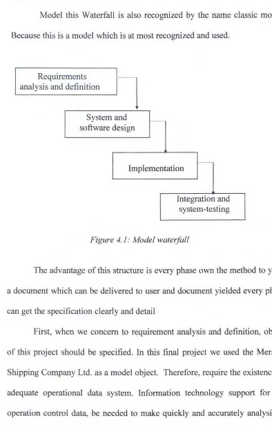
Model the Waterfall
Model this Waterfall is also recognized by the name classic model. Because this is a model which is at most recognized and used.
Requirements
analysis and definition
l
' - - - '
System and software design
Implementation
Integration and system-testing
Figure 4.1 : Model waterfall
The advantage of this structure is every phase own the method to yield a document which can be delivered to user and document yielded every phase can get the specification clearly and detail
of company which big sharing in business in the world of Indonesia maritime, with the professional worker, making Meratus as liner which have mount the natty and good company management, so that can be made by one of example for the liner of other specially in Surabaya and East Indonesia Area.
This company mount non-stopped till in 1987 having 11 ships and 1990 mounting again become 15 ships. Meratus representing first Indonesia Company serving special is transportation of interfiled container in Indonesia. Nowadays this Company have 29 ship counted in 2005. But unfortunately, Matos didn't have hull maintenance computerize database system. The computerize database system is helpful for maintenance data arrangement.
4.3 The Scope of Hull Maintenance System
Hull maintenance system can be dividing into some maintenance area. We should define the maintenance area of Meratus Shipping Company, especially in Fleet Division.
The Maintenance Area ofMeratus Shipping Company is: 1. Planning and Scheduling
The Schedule of Planned Maintenance System being determine by a team work (Ship Manager, Superintendent & Dock Monitoring). 2. Preventive Maintenance
3. Corrective Maintenance
Be determined in 2 conditions, between planned and unplanned maintenance. The aim is to repair and improve a facility condition until fulfill the requirement condition.
4. Emergency Maintenance
Can be included to the unplanned maintenance because the repmr action must do as soon as possible.
5. Continuous Improvement
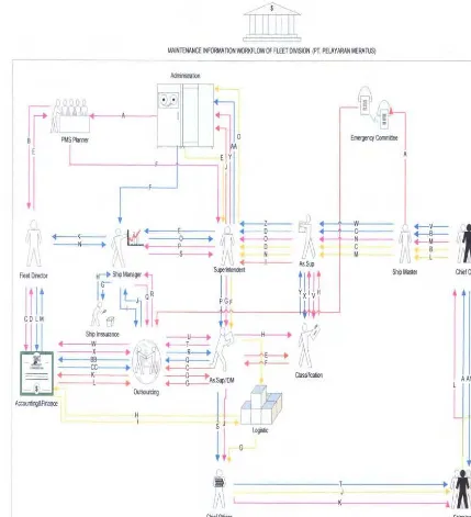
4.4 The Business Process of Corrective Maintenance
In the beginning, we must know the workflow of maintenance information from Meratus Shipping Company, especially in Fleet Division:
f.IAINTENANCE INFORf.IA TION V.ORKFLOW OF FLEET DIVISION (PT. PElAY ARAN MERA TUS)
- - - ,
r ~
r
Filet INeclor
II II
C 0 L M
Aa:ouriing&F~ance
Adnirisllaoon
Classification
.-- v - ~
...-s--+-M--B L
StipMaster ChiefOflicer
AAI U K
j I I
I
I
--- T ---~
J
C!iefOfficer Shipping Crews
For the example, the repair and material request workflow will be explained below:
1. Repair request
A. The crew make the repairing proposal to the Chief Officer
B. Chief Officer make a report of repairing proposal with fulfil the minutes
on the failure reports
C. The report of repairing proposal which have been agreed by Ship Master
will be delivered to the Assistant Superintendent
D. The report of repairing proposal will be delivered to the superintendent that commissioned to monitor the ship maintenance activity
E. Superintendent deliver the report of repairing proposal to the Ship
Manager to be analyzed of its repairing status
F. Ship manager require the data input from the fleet administration to analyze the ship repairing status
G. Ship manager will check the agreement data with the insurance company H. The insurance company will give the agreement data by Meratus officer I. When the occurring damage will influence the agreement with the
insurance company and need the outsourcing company. Hence, the ship manager will contact the outsourcing company in the agreement
J. The outsourcing company will offer the repairing plan to the ship manager K. The offering result from outsourcing company must get an agreement from
L. Head of Armada Division ask the report from accounting and finance division for allocated budged that planned for overall ship maintenance M. The detail report of ship maintenance from accounting and finance
division
N. Repairing plan that have agreed head of division will be delivered to the ship manager
0. Repairing plan that have agreed by ship manager will be delivered to the superintendent
P. Repairing plan that have agreed by the superintendent will be delivered by assistance of superintendent
Q. Assistant Superintendent makes coordination with outsourcing company.
Conduct the observation and control to all docking activity based on dock plan to fulfill the goals in its specified time schedule
R. Check all activity that conducted by Shipyard Company or contractor on the satisfaction notes. Monitor the docking report as following :
1. Docking report
11. Drawing of skin opened and result of ultrasonic test
iii. Report of clearance measure and magnaflux test 1v. Report of anchor and chain measuring
v. Satisfaction notes
VL Certificate and survey report from classification society
1. Report of intern docking (ship manager, ship crew, or company's labor)
a. report of docking work activity
b. report of spare part changing of machine and electricity c. report of using material or construction material
d. report of overhaul
e. report of merger test result
2. Help of conducting of final negotiation (include price) with shipyard company
S. When repairing task possible to conduct by the crew, so the repairing plan delivered to the Ship Master
T. Ship Master deliver the Repairing Plan to the Chief Officer (head of
machine room) to be conducted by the crew. The information transfer from Chief Officer to the crew can be a verbal or written command
U. The crew inform the repairing execution
V. Chief Officer send a report about the failure repairing execution to the
ShipMaster
W. Ship Master deliver the repairing report to the Ass Superintendent
X. Assistant Superintendent ask to classification society to check the result of
repairing failure
Z. Having taken steps of Inspection to the report or letter of repairing report hence the report will be delivered to Superintendent
AA. As soon as the repairing report have been checked by superintendent, repairing have been finished and its report enclosed by Fleet Administration
BB. Outsourcing company give a payment invoice to the accounting and finance division of PT Meratus
CC. Payment from PT Meratus to Outsourcing
2. Material request
A. The crew make the material requisition proposal to Chief Officer
B. Chief Officer fill the form of material requisition evidence
C. Having get the signature from Ship Master, the form will be delivered to
Assistant Superintendent
D. Assistant Superintendent deliver the form of material requisition to
Superintendent to be analyzed about its eligibility
E. Superintendent get the data of ship maintenance record, material supply
t
and material availability on the logistic division from the fleet administration
F. Things agreed by superintendent in the form of material requisition will be given Assistant Superintendent to contact logistics
H. If there are insufficiency of supply or defrayal, the logistics will deliver the invoice of material requisition to accounting and fmance division
I. Accounting and finance division will conduct the payment invoice
J. Ship Master will deliver its good to the crew to be used regularly
K. The crew give the report to Chief Officer about the good that have accepted
L. Chief Officer will make a acceptation report and must be signated by Ship
Master
M. Ship Master deliver the acceptation report to Assistant Superintendent
N. Assistant Superintendent deliver the acceptation report to Superintendent
0. Having the requisition and acceptation report have checked by
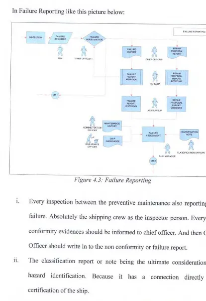
In Failure Reporting like this picture below:
c=-1
FAILURE- ~ ' - - -IN-FO-RM- EO...J
ABK
--- -e
CHIEF OFFICER I
u
ADMINISTRATION OFFICER
tfe
INSSURANCE
OFFICER
[
CHIEF OFFICER I
6
SHIP MANAGERy
Figure 4.3: Failure Reporting
FAILURE REPORTlNG
CLASSIFICATION OFFICER
1. Every inspection between the preventive maintenance also reporting the
failure. Absolutely the shipping crew as the inspector person. Every non conformity evidences should be informed to chief officer. And then Chief Officer should write in to the non conformity or failure report.
u. The classification report or note being the ultimate consideration for hazard identification. Because it has a connection directly for certification of the ship.
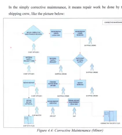
In the simply corrective maintenance, it means repair work be done by the
shipping crew, like the picture below:
I CORRECTIVE MAINTENANCE 1 I
/ ' MINOR CORRECTIVE
_. ', MAINTENANC~ , :~:~~~~ /
SHIPPING CREWS
CHIEF OFFICER I
SHIPPING CREWS
CHIEF OFFICER I SHIPPING CREWS
SHIPPING CREWS SHIPPING CREWS
u
u
ruJ
ASS.SUP SUP
•
Cl ADMINI STRATION DATA FILES
Figure 4.4: Corrective Maintenance (Minor)
1. The decision making for minor status of failure is chief officer
n. Every form for the hull corrective maintenance should be written by
chief officer
m. Ship master give an approval sign for every report which came out from
ship authority.
1v. The completion for every report is the responsibilities for the assistant
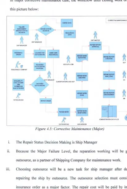
In major corrective maintenance case, the workflow until closing work order like this picture below:
I CORRECTIVE MAJNTENANCE 2
FAILURE
.
,::!~=$DEctSION
SHIP MANAGER
INSSURANCE COMPIW'(
AVAJLABIUTY,
COST&OCWN TIME EST1MA110N
flomO\JTSORCE
OUTSOURCING
SHIP MANAGER
ASS.SUPOfl»'
CLASSIACATlON & ASS.SUP
ADMINISTRATION DATA FILES
OUTSOURCING ASS.SUP&CW
Figure 4.5: Corrective Maintenance (Major)
1. The Repair Status Decision Making is Ship Manager
SUP
SM
Cl
n. Because the Major Failure Level, the reparation working will be given to outsource, as a partner of Shipping Company for maintenance work.
Ill. Choosing outsource will be a new task for ship manager after decide to
attention, because after choose any repair place from insurance reference, the shipping company wouldn't sacrifice the hug income to choose the repair place. Also with the cost & down time work that be offered by subcontractor &
dockyard, availability space for the vessel must support the repair execution. That being compared with the other outsource repair list, to obtain the minimum cost & down time.
iv. Every works will be monitor by Dock Monitoring or assistant superintendent if Dock Monitoring unattended to monitor the repair works.
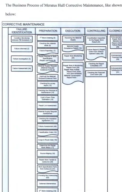
The Business Process of Meratus Hull Corrective Maintenance, like shown below:
CORRECTIVE MAINTENANCE
FAILURE
PREPARATION EXECUTION CONTROLLING CLOSING OUT
IDENTIFICATION
I
Condoion Mon<oring1
1 1• Wol1< Ordering (5) Receiving the Material
I
II
Classification Inspection Endorsement theRepair Wol1< &
between PM SChedule (1) Supply for the Repair Work Material Ace.
Checking the material Resu~ (25) Report (Closing
stoclt (6)
Material Supply
I
Fa~ure Report)I
I
(29)Failure Informed (2) Acceptance Report (10)
Failure Report & Repair
Failure Reporting (7)
-Order Form (Return Opened Case) (26)
I
Repair Wo11< MonHoringJ
Endorsement theI
Fa~ure lnvestigatiion (3)I
Repair Request & Wo11<
~ Financial Claim
Specitication (23) (30)
(Repair List F"'!!!U8l
-
II
Checking the ReportI
Failure Assessment (4a)I
Material Supply Request Rape~ Wol1< & Monooring Completely (27)
(Material Request Report Form (24) Endoresement the
Evidence Fo"2 · Repeir Wol1< Activily Satisfaction Note
Report Form (man- (31)
-
hour ,time schedule)II
Checking the Financtav Cost Claim (28)Approval the Material · Material Consumption
Request Evidence Form Report Form
Checking the survey ~
report(13)
Checking the Historical of maintenance (14)
Cost & Down Time
Estimation (15)
Repatr Ust Assessment
Material Supply Request
Assessment
Checking the Insurance
Agreement (11)
FaMure Assessment (4b)
Classification Order (12)
cargo & Route Data (18)
Determine the Repair
Wol1< Status (17)
SOurce Maping (18)
Repair Work Tender to outsource (20)
l
Wol1< Specification Formfrom Outsource (21)
-Choosing the Outsoun:ing
(22)
Deferred Maintenance
I
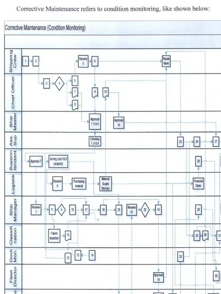
Z"' Wol1< Ordering (19)The Business Process of Corrective Maintenance, divide into 2 terms. The Corrective Maintenance refers to condition monitoring, like shown below:
Corrective Maintenance (Condition Monitoring)
Cl
§]--.!: ~I~
~
O.Q) a. ...
:co
en
t
...
Q) 0·~
i:0
rEt
....
Q)
:c
4EJ-()
...
-'--. Q-'--.*
_____. 'wow! Ajlproval, rEJ
J:(IJ 7,8&9 10
en~ ;
-· a.
~
G-~
~
~ :J
h
<(en 9
C:+'
81~
-c:Lg
'-Q) ~ Sortir~jlist8&9rr
Q)'O ~
a.c:
(propef1y)
II
:J Q)en ...
::t.
I~
~
~
:;; !II '0! 0 upply . .J ...
~ 8 ~
~
Q)
El-
~
j[~
Q.Cl
·- (IJ 1'-- 31
J:c: en(IJ
~
!Ec:
~
~ ~
~
!II 0
!II
·-(IJ ...
_(lj .
()0
r-::t. ·
f!J
15G-I
0 c:
0 0 1(
0~ 1i
...
a[~[,
... o
~
Q)+' Q) 0 _Q)
u. .:
0 """''f. .... ... A
Q)
~
~
-&
~
... o :J ...
og
.W:ll'l
I.[J
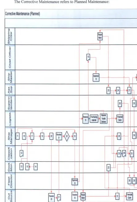
The Corrective Maintenance refers to Planned Maintenance:
Corrective Maintenance (Planned)
Ol
~
.5 ~
0.0) Q.l..
:cu
(/J 1.. Q) 0 B---t 0 ~ .~ .c () 1.. a.Ol--+0
:c~ ApjJoYal
(/)a! 10
~
· a.
0-%
~
1/) :J
~(/)
C""
·- c '-Q)
~
Q)'O ' - - 29 31
a.c
:J Q) (J) ...
:i.
-e..:.
~
'"
.~ __. Re<!ile ~ StiWI
Ol ~ ITQlerial ~
0 m
J
1..
Bs ~
~
Q)
Q.Ol
~
29 31·-a! '
-.Cc
(/)tO
~
I
~
B
~~
·- c l/1o
1/) ·- 25 31
a!"" _a!
()0
I
::t. ·
GJ
15@-I
oc 14
0 0
Cl~
1..
.... o
~
...291~
Q) ...
~
Olo _Q) u. .: 0 9 "···'}.. Q)ffiij
e-
~
... o
~
:J 1..
o5
rt m(/)
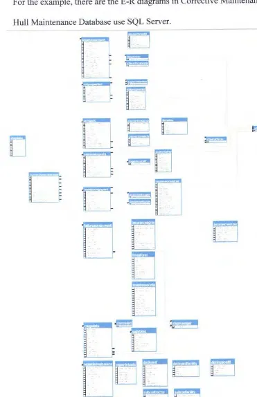
4. 5 Constructing the Entity Relationship Diagram
Defined the sequence in hull corrective maintenance for each
related person and unit in Meratus Shipping Company the next step is to
make and entity relationship diagram (E-R diagram). E-R diagram is tool
to describe the data requirements and assumptions in the system from a
top-down perspective. E-R diagram also illustrate the logical structure of
database.
There are three basic elements in ER models:
1. Entities are the "things" about which we seek information.
2. Attributes are the data we collect about the entities.
3. Relationships provide the structure needed to draw information
from multiple entities.
Developing an E-R diagram reqmres an understanding of the
system and its components. The step to buildE-R diagram is:
1. Define Entities: these are usually nouns used in descriptions of
the system
2. Define Relationships: these are usually verbs used in descriptions
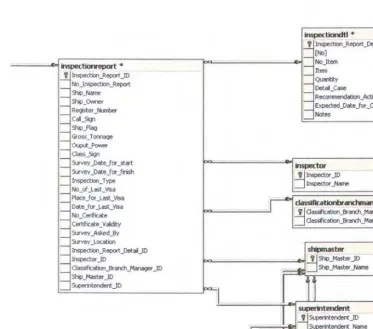
For the example, there are the E-R diagrams in Corrective Maintenance for Hull Maintenance Da